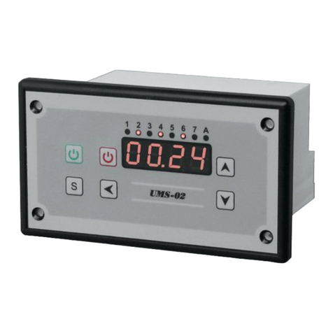
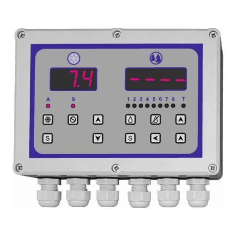
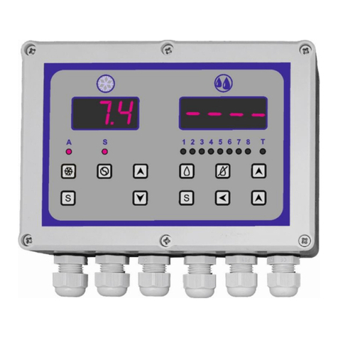
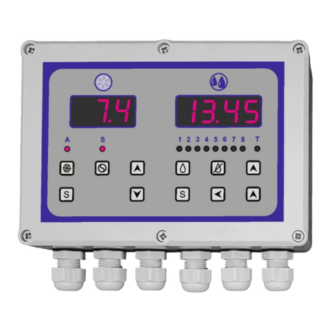
MAKOT UMS-02 User manual

UMS-02 Series Controllers are universal programmable time controllers.
The main application of these controllers is to control external devices within the process of washing the
milk and milking room coolers.
The controllers casing is designed to be built in.
CONTROLLER’S FUNCTIONS
1. Washing programs.
The controller has 8 washing programs. Factory settings include 2 milking room washing
programs and 2 programs to wash the coolers. The remaining programs are to be programmed by
the installer.
2. Programs setting and modification function.
The controller enables (the installer) to individually set the programs. Each program can include
up to 50 steps and can last up to 99 minutes. The programming is very simple and intuitive. It is
shown in detail in the manual in the form of pictures. The factory set programs can also be
modified according to specific needs.
3. Safety function in case of power outage.
In case of power outage the set program is stopped. When the power is back, the program will be
restarted at the same point it was at the moment the outage occurred. When setting this function,
it is possible to restrict the time, from 1 to 9 hours, in which it is possible to return to the
interrupted operation performed by the controller.
4. Service function enabling to test the correctness of work of the controller set.
This function allows to go to the next sequences of a program without waiting for the time to
pass. Skipping the stages is done by means of pressing a special button. This function is only
available for the installer.
5. Function allowing to return to factory settings.
In case an error occurs when setting the controller’s work program, there is always a possibility to
return to factory settings.
6. Function enabling to manually switch on the subpressure pump or the agitator.
7. Function enabling to start a program.
The program starts when a button located on the face of the controller is pressed manually or
when an external button attached to the controller is pressed. It is also possible to start the
program in an automatic way through an external device.
8. Pause function. This function enables to stop the running of a program at any time until it is
restarted. The restart causes the program to start operating at the same point when it stopped. The
pause function can be enabled by pressing a located on the face of the controller or by pressing an
external button attached to the controller.
9. Function switching the program off.
The controller is equipped with a button which enables to switch the program off without the
possibility to restart it at the same point. When the program is restarted it will start the program
from the very beginning.
10. Time remaining function. When the program is running the remaining time is visible on the
display. The time presented doesn’t include the time required to pour the water in.
11. Function showing the process of pouring the water in is finished, depending on the hydrostat
UMS-02 Controller is equipped with:
6 controller leads:
- one lead (relay No. 5) is equipped with contacts: normal close and normal open;
- all the other leads have normal open contacts;
-switched power input is conducted to enable providing any kind of power between 6 and
380 V
hydrostat input
input allowing to connect an external program starting button;
PRZEDSIĘBIORSTWO
PRODUKCYJNO HANDLOWE
MANUAL
CONTROLLER
SERIES
UMS-02
30-716 KRAKÓW ul.Przewóz 34/304
tel 012 657 91 44

The controller is equipped with:
LED display indicating the remaining program time during its realization [1]
Light emitting diodes designed to inform which relay is currently on during realization of a
given program[2];
A light emitting diode showing when the hydrostat is working [3];
A light emitting diode showing the device is in test mode [4];
A switch turning the washing program on. This switch also allows to manually stop a
program in progress [5];
A switch turning the washing program off [6];
A switch which serves to manually turn the relay No. 3 or 4 ON and OFF. It is also a setting
button when the device is in service mode (when the regulator settings are applied) [7];
A button allowing to access the settings mode [8];
Setting buttons (activated in the settings mode and in test mode) [9]
TECHNICAL INFORMATION
number of programs 8
number of factory set programs 4
maximum number of stages in each program 50
maximum time of one stage 99 min
minimum time of one stage 1 second
number of relay leads 6
load capacity of relay contacts 10A 250V AC
number of controller inputs max. 3
ohydrostat
oexternal „Start Program” button
display type LED
casing size 123 x 68 x 85 mm
power supply 230 V AC 50 Hz
safeguard IP30
safety class B
STRUCTURE
USM-02 controller is placed in panel casing to be built in.
SERVICING BY THE IMMEDIATE USER
A characteristic feature of the controller is the simple servicing by the user. Servicing requires to use
only two or three keys. All the other buttons are inactive for the immediate user disabling him from
accidentally interfering with the factory or installer settings.
ACTIVATION OF THE CONTROLLER
When power is connected to the controller it remains on stand-by. It is signalized by for bars being
lit up on the display panel.
The washing program can be enabled by pressing the green start button [5].
The controller allows to connect an external button which doubles the function of [5] button located
on the face of the controller.
When the start button is pressed the earlier set washing program is being executed.
During the execution of the program the display show the time remaining until the washing process
is over.
ATTENTION:
The time show by the display does not include the time required to pour in water when the controller
operates with a hydrostat
ACTIVATING THE WASHING PROGRAM
The washing program is activated by pressing the start button (green), this way a previously set program
is activated.
PAUSING THE WASHING PROGRAM
When the program is active it can be paused at any time. It is done by pressing the green start button
again. When the program is paused all the active relays are deactivated. It can be restarted again by
pressing the green start button once more. The program will continue from the moment it was paused.
DEACTIVATING THE WASHING PROGRAM
Whenever it is necessary the currently realized program can be stopped. It can be done by pressing the
OFF button (red).
When this button is pressed the program stops and deactivated completely and the controller switches to
stand-by mode. At this point, if the program is activated again it will start from the very beginning.

MANUAL ACTIVATION OF THE SUBPRESSURE PUMP OR THE AGITATOR
When this function is activated, the user can manually turn on the subpressure pump or the agitator.
Manual activation is only possible when no washing program is running. When a washing program is
running the manual control button is inactive. Which lead can be manually operated (subpressure pump
PP or the agitator PPR) is decided by factory or installer settings.
SERVICING BY THE INSTALLER
The controller is factory set for standard working conditions and it is designed for washing
the milk cooler –2 programs, and to control the washing of the milking room –2 programs.
Nonetheless, in order to provide optimized work of the controller in specific conditions, the
settings can be corrected to choose an appropriate program. The factory set washing programs can be
modified according to needs or a personalized program can be set.
When the controller is installed, the correctness of work of the entire washing system can be
checked in a fast mode.
SETTINGS CHART
Function
Symbol
Settings
Factory
settings
1
Entering the settings mode
U000
Access Code
121
2
Programs edition
EdPr
Editing the factory presets
and creating personalized
programs. Described
elsewhere within this
manual.
8 programs
See
Programs
Chart
3
Setting the program number
dPro
Pro1
Pro2
Pro3
Pro 4
Pro5
Pro6
Pro7
Pro8
Pro1
4
Setting the manual activation of the
subpressure pump or the agitator
UPP
0 –no function
1 –subpressure pump
2 –agitator
0
5
Setting the test program
UEL
0 –no function
1 –test function activated
0
8
Setting the maximum time without
Power supply after which the power is
restarted.
UAP
0 –no function (unlimited
time)
1 –9 h
9
9
Returning to factory settings when the
controller is next activated.
PdOd
0 –no function
1 –back to factory settings
0
ENTERING THE SETTINGS AND PROGRAMMING MODE
The controller is secured against accidentally entering the service settings mode that is available to
service and maintenance personnel only.
This includes:
- having to press and hold the settings and programming mode button [8] for approximately 15 sec.
- having to enter the access code, which is given in the Settings Table.
- entering the access code is effected in several steps.
ATTENTION.
You are requested not to make the access code available to end users.
Below is the graphic representation of the procedure for entering the accdess code which enables to
enter the settings and programming mode.
SELECTING THE FUNCTION TO BE EDITED
In the Settings Table are all the functions available with the description and the list of possible values to
be set. If it is necessary to change any parameter within the settings, enter the settings mode (see above).
Next select a particular function to be modified. Below is graphic representation of a change to the
factory settings for the washing program No 1.
EDITING THE PROGRAMS –EdPr Function
The controller is equipped with:
- 4 pre-programmed washing programs which can be edited according to needs by the
installer.
- 4 washing programs to be programmed by the installer and not pre-programmed.
Each program can consist of the maximum of 50 steps.
The following parameters are ascribed to each step:
- status of 6 relays;
- status of the hydrostat input;
- duration of the step;

RETURNING TO THE DEFAULT SETTINGS
In order to return to the default settings enter the controller settings mode. Select the PdOd option with
buttons ▲,▼. Confirm the selection by pressing button SChange the value from „0” to „1” using
button ▲. Then confirm the selection by pressing button S. again. Subsequently disconnect the power
from the controller and connect it again.
ATTENTION!
1. Returning to default settings will result in deleting all the settings from the controller’s
memory and simultaneously bringing back the default settings. Therefore this option
should be applied with proper care and awareness.
2. Returning to default settings is only effected once the controller’s power supply is
disconnected and connected again.
CONTROLLER OPERATING IN THE TEST MODE
The test mode function is designed for testing the correct operation of the washing system controlled by
UMS-02 controller.
Operating in test mode enables to manually speed up the particular steps of the program.
In order to set the test mode enter the settings mode and set the UEL function to 1.
Then confirm it by pressing S. To exit the setting mode press the red button.
The test mode operation is signaled by the flashing green light marked A.
Having switched on the program you can pass on to the following steps by pressing ▲. You can also go
back to the previous steps by pressing ▼.
Exiting the test mode:
- enter the access code;
- select the UEL function;
- set the value to 0
- confirm by pressing S;
- exit the settings by pressing the red button
ATTENTION
Having finished the tests of the washing system it is absolutely essential to remember to return to the
regular operation. During the regular operation the green light must not be on.
PRE-SET PROGRAMS
The controller contains 4 pre-set programs presented below. The remaining 4 programs are empty..
Program No 1
LED diode No
1
2
3
4
5
6
7
REMARKS
STEP
TIME
CW
ZW
PP
PML
ZZ
PMY
H
1
15:00
0
1
0
0
0
1
1
Max. time
2
03:00
0
0
1
0
0
1
0

3
00:30
0
0
1
1
0
1
0
4
15:00
1
0
0
0
1
1
1
Max. time
5
07:30
0
0
1
0
1
1
0
6
03:30
0
0
1
0
0
1
0
7
00:30
0
0
1
1
0
1
0
8
15:00
0
1
0
0
0
1
1
Max. time
9
05:00
0
0
1
0
0
1
0
10
00:30
0
0
1
1
0
1
0
01:05:30
Program No 2
Relay No
1
2
3
4
5
6
REMARKS
STEP
TIME
CW
ZW
PP
PML
ZZ
PMY
H
1
15:00
0
1
0
0
0
1
1
Max. time
2
04:00
0
0
1
0
0
1
0
3
00:30
0
0
1
1
0
1
0
4
15:00
1
0
0
0
1
1
1
Max. time
5
11:30
0
0
1
0
1
1
0
6
02:30
0
0
1
0
0
1
0
7
00:30
0
0
1
1
0
1
0
8
15:00
0
1
0
0
0
1
1
Max. time
9
06:00
0
0
1
0
0
1
0
10
00:30
0
0
1
1
0
1
0
01:10:30
Program No 3
LED diode No
1
2
3
4
5
6
7
STEP
TIME
CW
ZW
PM
PPR
ZZ
PMY
H
1
02:00
0
1
0
0
0
1
0
2
00:30
0
1
1
1
0
1
0
3
02:00
0
0
1
1
0
1
0
4
02:30
0
0
0
0
1
1
0
5
02:30
1
0
0
0
0
1
0
6
00:30
1
0
1
1
0
1
0
7
05:00
0
0
1
1
0
1
0
8
03:00
0
0
0
0
1
1
0
9
02:00
0
1
0
0
0
1
0
10
00:30
0
1
1
1
0
1
0
11
03:30
0
0
1
1
0
1
0
12
04:00
0
0
0
0
1
1
0
28:00
Program No 4
LED diode No
1
2
3
4
5
6
7
STEP
TIME
CW
ZW
PM
PPR
ZZ
PMY
H
T
1
02:30
0
1
0
0
0
1
0
40
2
01:00
0
1
1
1
0
1
0
40
3
01:00
0
0
1
1
0
1
0
4
02:30
0
0
0
0
1
1
0
5
02:30
1
0
0
0
0
1
0
45
40
6
01:00
1
0
1
1
0
1
0
45
40
7
04:30
0
0
1
1
0
1
0
8
03:00
0
0
0
0
1
1
0
9
02:30
0
1
0
0
0
1
0
40
10
01:00
0
1
1
1
0
1
0
40
11
02:30
0
0
1
1
0
1
0
12
04:00
0
0
0
0
1
1
0
28:00
Total time
CW –warm water relay ZW –cold water relay
PP –subpressure pump relay PML –milk pump relay
ZZ –dump valve relay PMY –washing relay
H- hydrostat T –water heating
D –dispensing
CW –warm water relay ZW –cold water relay
PM –washing pump relay PPR –mixer relay
ZZ –dump valve relay PMY –washing relay
H- hydrostat T –water heating
D –dispensing
CONNECTING THE CONTROLLER
Attention
1. Signal L of 230 VAC should be given to the external start button and the hydrostat input;
2. Relay No 5 has normally closed input NC and normally opened input NO

Mounting slot
Other manuals for UMS-02
1
Table of contents
Other MAKOT Controllers manuals
Popular Controllers manuals by other brands
Siemens
Siemens RWD62U Installation and commissioning guide
Maxcess
Maxcess Fife Polaris DP-20 User manual/instructions

Galcon
Galcon Galileo manual

HomeSeer
HomeSeer HomeTroller Zee S2 Getting started guide

Moxa Technologies
Moxa Technologies ioThinx 4530 Series user manual
Munters
Munters CCU5000 Manual for use and maintenance
