Malema BCV-980 User manual

malema.com
Corporate Headquarters West Coast Headquarters Asia Pacic Headquarters
1060 S Rogers Circle
Boca Raton, FL 33487
P: (561) 995-0595 F: (561) 995-0622
2329 Zanker Road
San Jose, CA 95131
P: (408) 970-3419 F: (408) 970-3426
35, Marsiling Industrial Estate Road 3,
02-06, Singapore 739257
P: (65) 6482-3533 F: (65) 6484-4231
INSTRUCTION MANUAL
FOR
BCV-980
Bio-Pharmaceucal Proporonal
Pinch Control Valve
malema.com
INTRODUCTION:
The BCV-980 is an intelligent, Proporonal Control Valve intended for BioPharmacucal applicaons. The BCV is an electrically
operated Pinch Valve with built-in, sophiscated control capabilies. Electrically operated Pinch valves oer several advantages
over other valve construcons. For BioPharama applicaons these advantages include:
• No added materials in contact with the media; only the tube-manifold contacts the media
• No crevasses, cracks, clogging or dead spots
• Unaected by parculates in the stream
• Simple, robust & straight through design
• No Pneumac complicaons or facilies required for operaon
• Self-cleaning
• Tight shuto
• Minimal turbulence & fricon
• Minimal maintenance required. No bearings, seals or packings
• Low Total Cost of Ownership; other than the single use manifold there are no other consumables
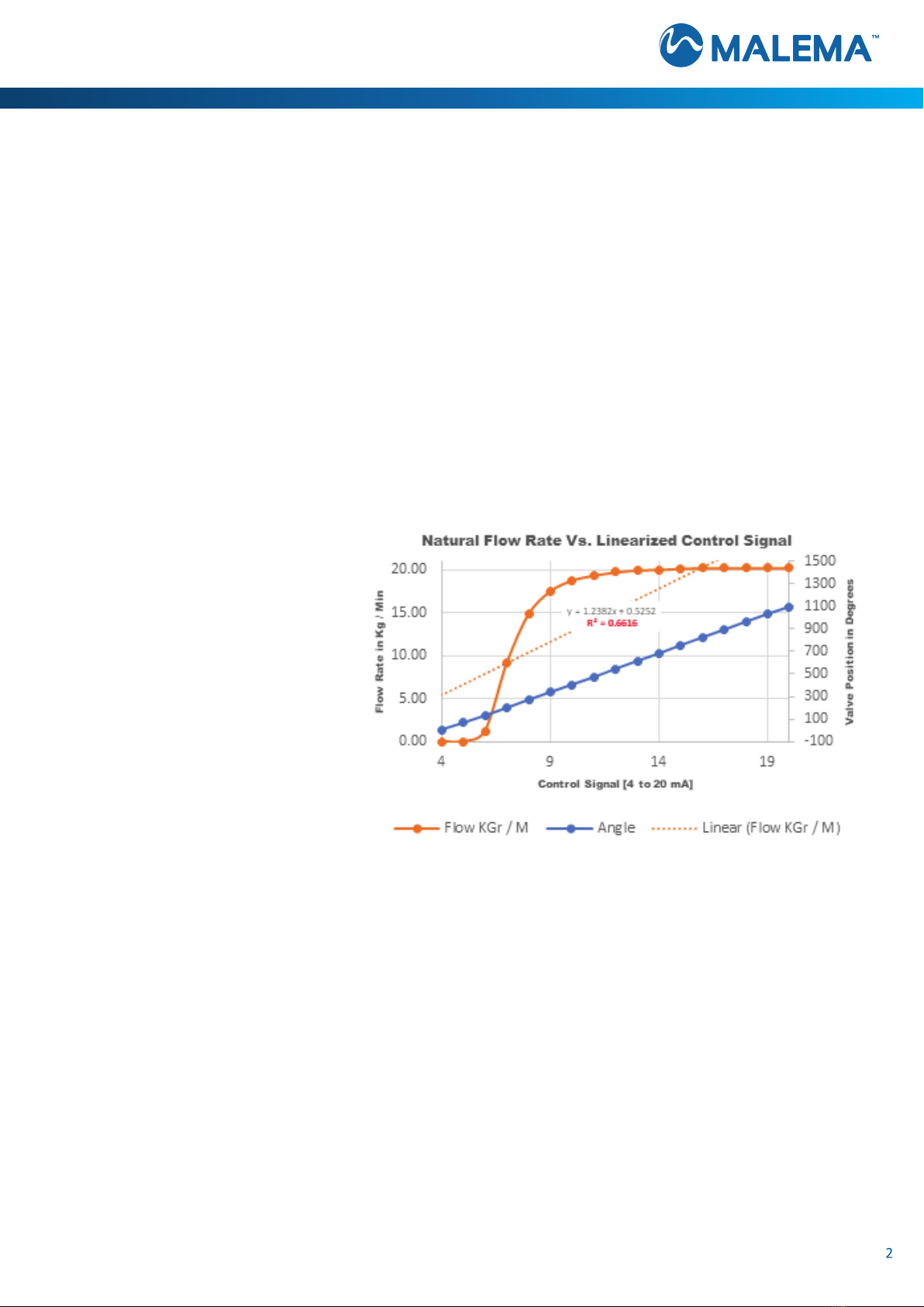
Classic pinch valves provide minimal throling control capabilies; most of the control occurs during the rst 1/4 to 1/3 of the
control range [Coecient of Determinaon, i.e.: R2 values around 66%]. Malema ulizes a complex polynomial algorithm
expanding upon the classic performance
of pinch valves. By linearizing valve perfor-
mance [ow rate] Vs. control signal rather
than linearizing valve posion Vs. control
signal. While using Malema’s linearizaon
scheme a slight change in control signal re-
sults in a similar [linear] change in ow rate
[Coecient of Determinaon, i.e.: R2 >95%].
This proprietary linearizaon scheme can be
disabled from Malema’s GUI.
Control Resoluon: The BCV-980 ulizes a ten(10) pitch [i.e.: ten(10) threads per inch] Acme screw and an eight thousand
(8,000) count per revoluon opcal encoder monitoring valve posion. A sixteen(16) bit ADC converts the command setpoint
signal into 65K steps between fully OPEN and fully CLOSED posions. Assuming one hundred LPM is the max ow through a
1” ID tube, individual step resoluon is about 5 ccm or ≈ 0.5% of Full Scale.
Resoluon varies with tube size. Smaller sized tubes may have fewer total steps available. Malema oers a high resoluon ver-
sion for these applicaons.
2

malema.com
Table of Contents
INTRODUCTION 2
OPERATING MODES 4
SAFETY, CAUTIONS 5
DIMENSIONAL DRAWINGS 5
PRODUCT SPECIFICATIONS 6
GETTING STARTED 7
TUBING INSTALLATION 8
REMOTE MANIFOLD INSTALL COMMAND 8
PANEL MOUNTING 9
CALIBRATION, LINEARIZATION 10
PINOUT, WIRING Diagrams 12
CIRCUIT DIAGRAMS 14
CABEL DETAILS 17
FRONT PANEL DISPLAY 16
TYPICAL, STAND-A-LONE TFF APPLICATION 17
CONTROL STRATEGY 18
MALEMA GUI 18
GUI CONTROL WINDOW 20
WARRANTY 21
CERTIFICATE OF COMPLIANCE 23
APENDIX of SELECTED DATA 24
3
© 2020 Malema Engineering Corporaon. All rights reserved.
Malema, Malema Sensors, and Malema Engineering Corporaon are service marks of Malema Engineering Corporaon. All other trademarks are property of their respecve owners.
Malema supplies this publicaon for informaonal purposes only. While every eort has been made to ensure accuracy, this publicaon is not intended to make performance claims or
process recommendaons. Malema does not warrant, guarantee, or assume any legal liability for the accuracy, completeness, meliness, reliability, or usefulness of any informaon, product,
or process described herein. We reserve the right to modify or improve the designs or specicaons of our products at any me without noce. For actual product informaon and recom-
mendaons, please contact your local Malema representave.

malema.com
INTRODUCTION (CONTINUED)
OPERATING MODES:
The BVC-980 is an intelligent, proporonal, pinch, control valve.
1. The BCV-980 – Supports 1/8” through 1”I.D. tubing
2. The BCV-980 supports virtually any biopharma tube construcon including:
a. Unreinforced tubing
b. Braid Reinforced tubing, or
c. Double Braid Reinforced tubing
The product has two(2) operang modes:
1. REMOTE Mode: In this mode, the device responds to an external 4 to 20 mA signal generated by a remote
operator or control system [i.e.: 4 mA = FULLY CLOSED; 20 mA = FULLY OPEN]. Valve posion is soware adjusted to
approximately linearize ow rate Vs. signal [I.e.: 12 mA ~= 50% FLOW]
2. TFF Mode: Based on an analog Setpoint signal, the device monitors up to three(3), external analog transducer
signals, adjusng valve posion based on the TFF Equaon. On applicaon, other algorithms can be supported.Conrm
that you have the following items:
When panel mounted in a standard 1/4 DIN panel cut-out [88 mm X 88 mm], the BCV-980 provides IP65 (protecon against
water jets) NOTE: Care must be taken in a panel layout as the exible tube running through a BCV-980 may obscure adjacent
panel cut-out locaons. The BCV-980 supports mounng in any orientaon.
The BCV-980 accepts tubing of virtually any size between 0.125” ID through 1.000” ID. Factory pre-conguraon for any size
or tube conguraon is available and recommended. One(1) nger guard is supplied with each BCV-980. Several nger guards
are available depending on tube OD
4
STORAGE AND HANDLING
Storage condions
Store the product under packed condions in an an-stac bag. The storage place shall be free from moisture, mechanical shock
and vibraon. The ambient temperature shall be between 3°C and 60°C and the humidity between 5% and 80% R.H. without
condensaon
Unpacking and Product Inspecon
On delivery, check the product for damage. Conrm that the model code on the label matches the specicaon in the purchase
order.

malema.com
SAFETY CAUTIONS
The BCV-980 is a Pinch Valve: use care keeping ngers, etc. out of the
pinch mechanism! Severe & painful damage is possible.
DIMENSIONAL DRAWINGS: BCV-980
For Reference Only
5
BCV-980; general arrangement

malema.com
6
Performance Specicaons
Fluid Temperature 4° – 60°C *
Ambient: Temperature/Humidity 0° – 40°C / 30% – 80% RH, non-condensing
Maximum Expected Operang Pressure 6 bar (g)
Dierenal Pressure range 0 - 6 bar
Power Supply Input 24 Vdc 10%
Current Consumpon 4 A max, 1A typical
Alarm Signals Max 30 Vdc, 200 mA NPN open collector
Signal Out (Valve Posion) 4 - 20 mA
Weed Parts None
Non Weed Parts, Enclosure Non-magnec 316L Stainless Steel,
Non-magnec Powder-coated Stainless Steel
Mounng Orientaon Performance unaected by mounng orientaon
Fluid Connecons 1/8” – 1” ID exible tube, braided or un-braided
Ingress Rang IP65
Panel Mounng Universal thickness — accommodates any panel thickness
Panel Cutout 1/4 DIN (90mm x 90mm)
Mass 2.6 kg – 3.3 kg
* Consult the factory for higher temperature applicaons
* Up to four external analog signals. Implements standalone TFF control
Electrical Specicaons
Material Specicaons
Physical Specicaons

malema.com
GETTING STARTED
Unpack and mount the BCV-980, using the included Silicon Sponge Gasket, through a standard ¼ DIN panel cut-out [88mm X
88mm]. Panel or surface mounng is essenal to achieve IP65 ingress protecon. The BCV-980 is fully connectorized using
shielded Hirose connectors. [Hirose connectors are readily available from Digikey, Farnell, Mouser, Newark, and others.] Fully
assembled cables are available. Consult Malema factory for details
FINGER GUARD INSTALLATION:
The FINGER GUARD is packaged separately. Using provided 3/16” Allen wrench and provided PIN SCREWS, install the FINGER
GUARD. Finger ght is adequate.
FINGER GUARD INTERLOCK:
The FINGER GUARD is magnecally interlocked with the BCV-980 crush mechanism. The DRAW BAR will not move unl the
FINGER GUARD is replaced. Various FINGER GUARDS are available depending on the tube size in use. Contact Malema for the
FINGER GUARD(s) required for your applicaons.
POWER, CONTROL & SIGNALING
A male, twelve(12) pin, Hirose connector supports device power along with primary signaling. A twelve(12) core, three(3) meter
long, connectorized cable with stripped ends is provided with each BCV-980.
The BCV-980 accepts up to four(4) external analog signals and provides two(2) discrete, OPEN Collector STATUS / ALARM Outputs
[NPN, 30 VDC, <200 mA], one(1) discrete Input along with two(2) analog Output signals. One(1) of these analog outputs is
proporonal to valve posion and provides CLOSED Loop feedback to a remote controller. The other analog output reports μP
temperatures or alternavely, this output can be ulized to drive other components in your system [i.e.: Pump speed(?), consult
Malema factory for details].
The device communicates over [Malema Addressable Sensor Network] MASN (RS-485 serial). Up to two hundred y(250)
devices can be supported by a single RS-485 master controller. MASN supports viewing & seng of device conguraon along
with near real-me data logging on a customer supplied computer or laptop.
GROUNDING
The four(4) rear mounted 4 mm studs provide for a convenient GROUND or EARTHING connecon.
A thumb nut is provided for this essenal electrical connecon. Failure to properly GROUND the
BCV-980 voids the warranty and CE Compliance.
EXTERNAL SENSORS
If ordered separately, Three(3), female, twelve(12) pin connectorized cables support up to three(3) aached, external sensors.
[These are oen pressure transducers, or ow meters monitoring the condions surrounding a TFF module.] The BCV-980
provides +24 VDC, [up to 100 mA] power to these external sensors and accepts Discrete & Analog signals in return. If ulizing
TFF Mode, these external signals are then ulized, internally by the BCV-980, to modulate valve posion. Addionally, these
external sensor interfaces provide:
• A POWER Cycling capability
•A Zero RESET signal
• Discrete signal “Hand Shaking”
• RS-485 Serial Communicaon based on the Malema Addressable Sensor Network Protocol (MASN):
o Baud Rate = 115,200
o Data Bits = 8
o Parity = NONE
o Stop Bits = 1
o Flow Control = NONE
TUBE SIZE SELECTION
The standard BCV-980 ships pre-linearized for several standard tube sizes. These sizes can be selected from a “drop down” menu
accessible from the Malema GUI.
7
malema.com
8
TUBE INSTALLATION
Tubing installaon proceeds from the front of the BCV:
1. Ensure the DRAW BAR is OPEN. A remote panel mounted key switch accomplishes this funcon.
2. OPEN the FINGER GUARD
3. Insert the tube-manifold
4. CLOSE the FINGER GUARD
5. RESTORE the key switch to the normal or operate posion
6. The BCV-980 executes an inializaon roune locang the zero(0) ow locaon
7. The BCV-980 is now ready to operate
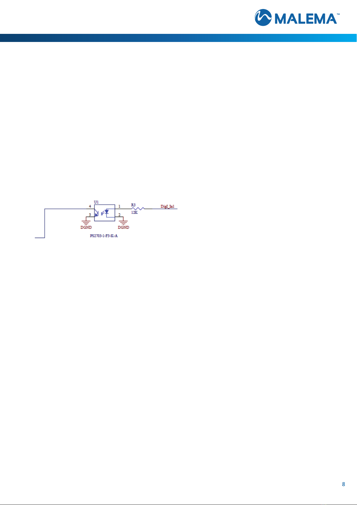
REMOTE MANIFOLD INSTALL COMMAND
This unit is provided with REMOTE MANIFOLD INSTALL COMMAND. An external +24 VDC signal applied to the DI pin [PIN #8,
WHITE/BLACK] on rear panel mounted connector P0 causes the DRAW BAR to fully OPEN so, manifolding can be easily installed
or removed. When this signal is removed the BCV-980 slowly closes under reduced torque unl motor stall occurs. At this point
a new ZERO posion is established and the system returns to Normal operaon.
The internal circuit for this funcon is shown here:
VALVE LINEARIZATION
The BCV-980 ships with Malema’s linearizaon scheme enabled. The feature can be disabled by unchecking the “Enable LIN
funcon” Check Box in the Bio Control Valve sengs Window of the GUI. A Valve Linearizaon Vs. Flow Rate Procedure is
provided [see page 11] should you require a unique linearizaon result

malema.com
9
PANEL MOUNTING
The BCV-980 panel mounts through a standard ¼ DIN panel cutout [88mm X 88mm].
An ORANGE Silicone Rubber sponge gasket is provided with each BCV-980. When properly installed with the gasket the BCV-980
provides IP65 ingress rang; i.e.: protecon against water jets.
CAUTION: [The front of the
BCV-980 provides IP65. IP30 protecon
is provided for the poron behind the
panel or when not panel mounted.]
GROUNDING:
Any of the four(4), 4 mm Rear Mounng
studs can be used for GROUNDING.
[OPTIONAL, BENCH TOP-MOUNTING]
A clear, blue nt, PVC Bench-Top mounng accessory is available. Consult Malema for details.
malema.com
VALVE LINEARIZATION VS. FLOW RATE PROCEDURE
Scope:
To set the BCV angles for minimum and maximum ow rates
Setup requirement:
• PC with GUI to indicate ow rate
• Calibrated Flow meter
• BCV-980 with power/signal cable
• 4-20mA signal generator
• Hose to test
o Use the same tubing / hose that will be used in producon
10
Procedure:
1. Place the tubing into BCV-980 with no pressure and
power-up the unit
a. On inial POWER-UP the BCV-980 slowly
closes while seeking full closure. This is
automac and requires several seconds.
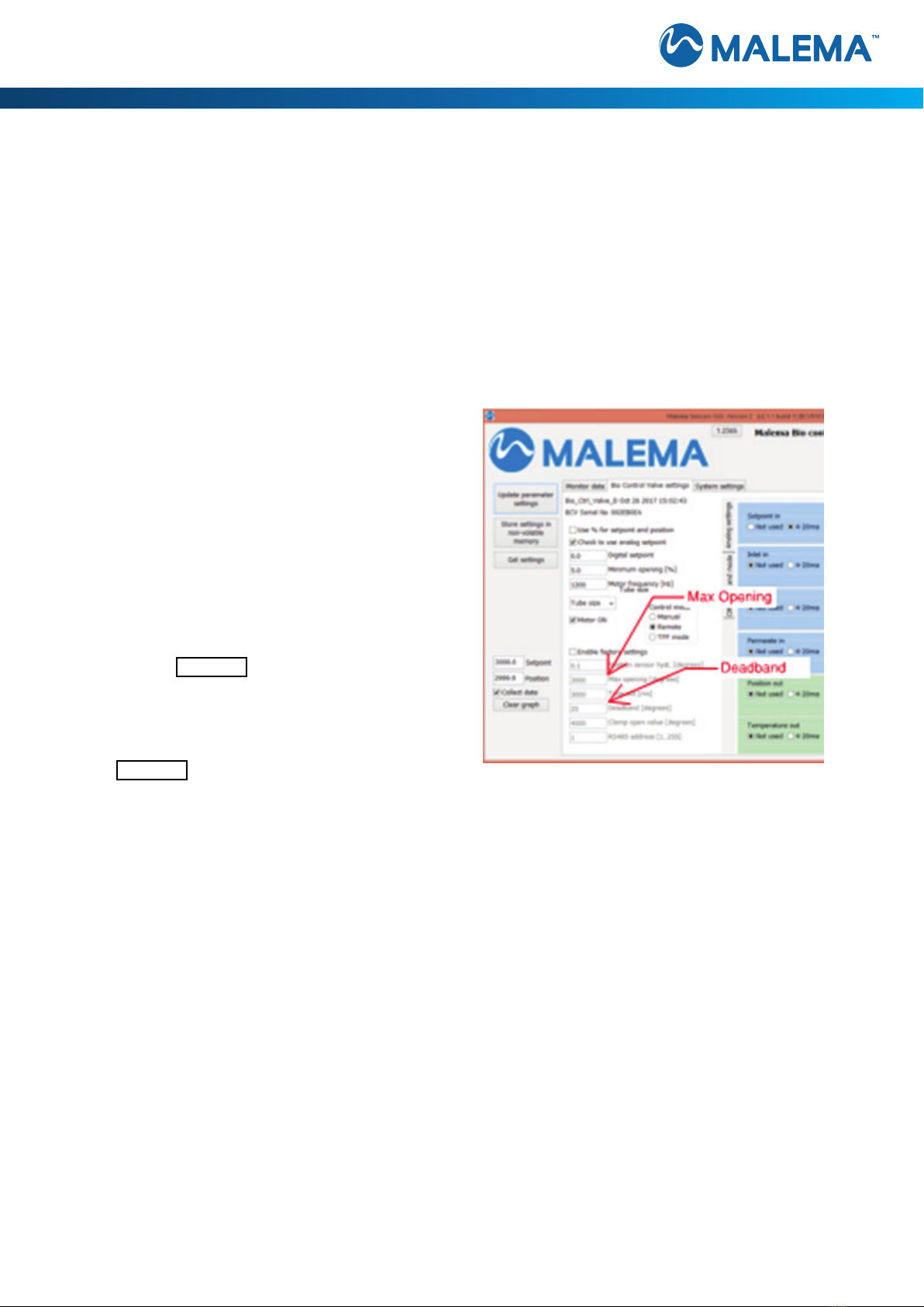
2. Aer the fully closed point is located, set the BCV
to remote mode.
3. Set maximum valve opening of BCV-980 allowing
maximum ow thru the tube.
4. Establish owrate thru the ow meter equal to 110%
of desired owrate:
a. [i.e.: if 2L max desired; set ow to 2.2L]
5. Slowly decrease the maximum valve opening of the
BCV-980 Valve angle unl the ow meter reported
ow rate is 2L/min
6. Enter this angle value in the GUI Maximum open-
ing eld
7. Connue to decrease the angle unl no ow is
observed
8. Enter this angle value in the GUI Deadband eld
9. Set the BCV to remote operaon mode:
a. The Status LED turns BLUE in Remote mode
420 Max opening [degrees]
120 Deadband [degrees]
10. Hook-up a 4-20ma analog signal generator to the the Analog setpoint input of main power cable
11. Set input setpoint signal to 20ma
a. Conrm the BCV-980 opens to the GUI maximum opening angle
b. Conrm ow rate equals the maximum desired owrate
12. Set setpoint to 4ma
a. Conrm the BCV-980 closes to the GUI Deadband angle
b. Conrm minimum ow rate or pressure observed.
Note: The Deadband angle adjustment is an iterave process
13. Power cycle the unit and verify the setpoint and owrates are correct
14. Record owrates for the following setpoints:
a. 4ma __________
b. 5ma __________
c. 8ma __________
d. 12ma __________
e. 16ma __________
f. 20ma __________
malema.com
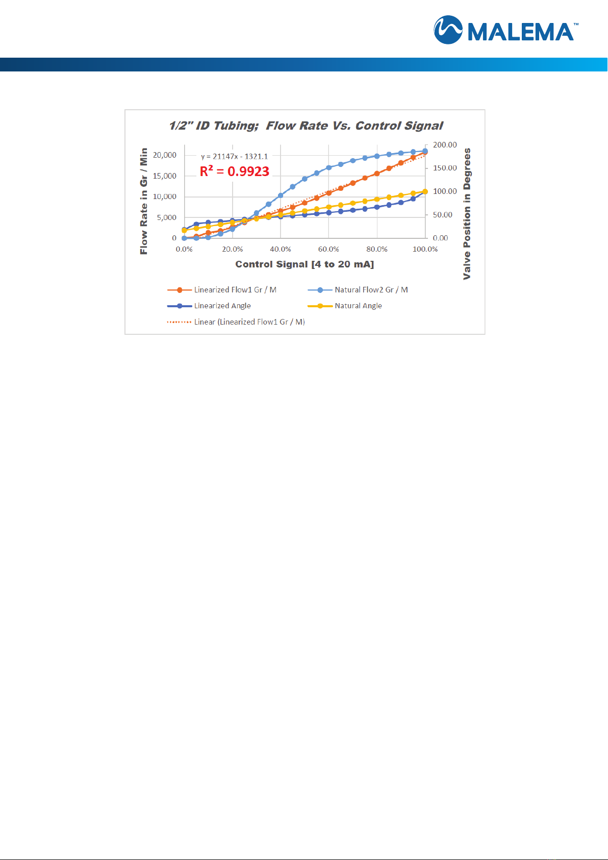
Typical Linearizaon Results
11

malema.com
12
Connector PINOUTS
Connector FUNCTIONS:
MAIN POWER / CONTROL CONNECTOR [twelve(12) Pin, Male]:
1. RED +24 VDC ±10%; POWER INPUT; 2 AMP
2. BLACK WARNING OUT; OPEN COLLECTOR
3. PINK ALARM OUT; OPEN COLLECTOR; this line shorts to GROUND in the event of drive motor stall.
4. GRAY DIGITAL OUTPUT; FINGER GUARD OPEN
5. BLUE RS485 A+; serial communicaons ulizes Malema Addressable Sensor network protocols;
up to two hundred y(250) devices can be supported on a single channel
6. WHITE RS-485 B-
7. RED / BLACK SETPOINT INPUT; a congurable analog INPUT VIA the Malema
GUI ; could be 4 to 20 mA; 0 to 5 VDC; 0 to 10 VDC or 1 to 5 VDC
8. WHITE / BLACK DIGITAL INPUT 0; A +24 VDC signal applied to this PIN implements the REMOTE MANIFOLD INSTALL
COMMAND [see line 132 on page 7 of this USER GUIDE]
9. YELLOW ANALOG OUT 1; An analog output signal proporonal to valve posion, 4 mA = valve
closed, 20 mA = valve fully opened.
10. BROWN ANALOG OUT 2; Analog output signal proporonal to μP temperature2 ; 4 mA = 0oC,
20 mA = 100o C; could be congured to mirror one(1) of the remote sensor inputs or some calculated value
11. GREEN GROUND
12. VIOLET GROUND
1Congurable VIA the Malema GUI; default is 4 to 20 mA; other opons 0 to 5 VDC; 0 to 10 VDC or 1 to 5 VDC
2This signal can be repurposed – consult Malema for details

malema.com
13
REMOTE SENSOR CONNECTORS [i.e.: RP 1; RP 2 and RP 3] [twelve(12) Pin, Female]:
1. RED +24 VDC ±10%; POWER INPUT; 1 AMP
2. BLACK REMOTE POWER; +24 VDC ±10%; 0.100 AMP; these circuits are
controlled by the BCV-980 allowing interrupon or POWER Cycling of connected sensors
3. PINK DIGITAL OUTPUT 1 thru DIGITAL OUTPUT 3; these are OPEN COLLECTOR circuits enabling the BCV
to send command signal to aached sensors; unimplemented
4. GRAY ZERO 1 thru ZERO 3; these signals allow the BCV-980 to force a ZERO funcon for remote
sensors; these signals are congurable in rmware either supplying +24 VDC or GROUND as required by the
remote sensors
5. BLUE RS485 A+; serial communicaons; ulizes Malema Addressable Sensor network protocols;
up to two hundred y(250) devices can be supported on a single channel
6. WHITE RS-485 B-
7. RED / BLACK ANALOG INPUT 1 thru ANALOG INPUT 3 [or SUPPLY, RETENTATE or PERMEATE]; congurable analog
signal carrying the values generated by the remote sensors
8. WHITE / BLACK DIGITAL INPUT 1 thru DIGITAL INPUT 3; these signals allow the remote sensors to report ALARM
or FAULT condions to the BCV-980
9. YELLOW RESERVED
10. BROWN RESERVED
11. GREEN GROUND
12. VIOLET GROUND
3Requires custom rmware – consult Malema for details

malema.com
14

malema.com
15
CABEL DETAILS

malema.com
FRONT PANEL STATUS DISPLAY
16
The front panel of the BCV-980 supports two(2) LEDs:
•POWER – This LED glows when adequate 24 VDC power is applied.
LED color changes based on currently selected operang mode:
o BLUE – Remote Mode
o GREEN – TFF Mode
•CLAMP – The CLAMP LED glows RED when the FINGER GUARD is OPEN
or missing. At these mes all operang modes are disabled. To restore
funcon replace & CLOSE the FINGER GUARD.

malema.com
17
TYPICAL, STAND-A-LONE, TFF APPLICATION

malema.com
Malema has manufactured Liquid Flow Controllers for many years. Over this me, we have developed sophiscated, propri-
etary, expert, self-learning, rule based, PID control algorithms. These algorithms overcome the shortcomings typically found in
PID process control.
Quick responses to process upsets or changing condions are not followed by overshoot, undershoot and delays associated with
quarter wave decay. Malema ow controllers typically achieve stable control in less than one(1) second aer a process upset
or step change in control setpoint. Systems have normal responses to these events. By observing and recognizing these dis-
rupons as they occur, Malema ow control algorithms take the appropriate steps early on, reestablishing and restoring control
quickly. Just like a truck driver in the mountains knows to conserve his brakes and momentum as he descends so, he’ll need less
addional energy ascending the next hill.
18
CONTROL STRATEGY
Copy the Malema Sensors applicaon from the CD to a local drive and create shortcut to desktop.
Open the Malema applicaon, click on the text eld labeled with the COM port number to connect PC app to BCV-980 located
in the upper right-hand corner.
To capture a graph, check the Collect data checkbox.
Graph below shows Posion and Setpoint with ramp up/down of 500 deg.
MALEMA GUI

malema.com
Using the GUI to control Digital setpoint:
• Connect the RS485 to the cable.
• Open the Bio Control Valve Sengs tab.
• Set the control mode to Remote.
• Click checkbox “Motor ON”.
• Enter a value in degrees or percent to the Digital setpoint window.
• Click the “Use % for Setpoint and posion” if entering percent valve.
• Click on Update parameter sengs buon.
Note: Update parameter sengs buon must be clicked when any seng has changed.
Controlling the Valve using 4-20mA analog signal:
• Hook up the 4-20mA connecons to the command signals of control cable provided.
• Set the control mode to Remote.
• Click checkbox “Check to use analog setpoint”.
• Select Setpoint input type: 4-20mA, 1,5V, 0-5V, or 0-10V.
Using TTF mode:
• Set the control mode to TFF.
• Connect the other inputs.
• Select the input type for each input: 4-20 mA, 1,5 V, 0-5 V, or 0-10 V.
19

malema.com
20
Bio Control Valve sengs Window
GUI CONTROL WINDOW
Table of contents
Popular Control Unit manuals by other brands

Sloan
Sloan G2 Optima Plus Maintenance Guide

Vega
Vega VEGAFLEX 66 operating instructions

ClimateMaster
ClimateMaster Flow Controller 3 Installation, operation & maintenance instructions

Motorola solutions
Motorola solutions PMLN6827 manual

Victaulic
Victaulic FireLock 912 Installation instructions manual

Blonder tongue
Blonder tongue QTPCM-4 manual


Advantech
Advantech B+B SmartWorx iMcV-Giga-MediaLinX TX/SFP user manual

KWC
KWC AQUAREX WC AQRM550 Installation and operating instructions

COMEPI
COMEPI MS1A31-024 manual

EOS
EOS ECON F1 Assembly and operating instructions

Hach
Hach SC4200c User instructions

Honeywell
Honeywell Silent Knight SK-Monitor Installation and maintenance instructions