Mallory HYFIRE VI Series User manual

HYFIRE® VI Series Electronic Ignition Controls
Instruction Manual
Part#: 685, 6851

HYFIRE®VI SERIES OF ELECTRONIC
IGNITION CONTROLS
HYFIRE®VI Ignition System Part No. 685, Advanced
HYFIRE®VI Ignition System Part No. 6851, Basic
For applications triggered by points, Mallory Electronic Ignition Distributor (all models), original equipment electronic
ignition amplifi ers and magnetic trigger pulses (magnetic pickup distributor or crank trigger ignition). Optional adapters are
available for easy connection to early model Delco/GM HEI Systems, late model GM HEI/EST Systems, Ford TFI Systems,
and OEM magnetic pickup (non-computer; Ford DuraSpark, GM HEI and Mopar/Chrysler Electronic Systems).
This product is legal to sell, distribute or install on vehicles in California. C.A.R.B. Executive Order D-70-26.
NOTE: Mallory HYFIRE® VI Electronic Ignition Controls are not compatible with distributorless systems or positive
ground applications. The RPM Limiter in the HYFIRE® VI (Part No. 685) will not work properly with odd-fi re or
semi-even fi re V6 applications.
Parts included in this kit:
1 HYFIRE®VI Electronic Ignition Control - Part No. 685 or 6851
1 Ignition Control Harness - Part No. 29348
2 Terminal Connectors - Part No. 450
1 Bypass Connector
4 Cable Ties
2 Spade Terminals
8 Ring Terminals, 1/4”
1 Ring Terminal, 3/8”
5 Spade Receptacle Terminals
4 10-32 Screws
4 10-32 Nuts with Lockwashers
INSTALLATION INSTRUCTIONS
WARNING: DO NOT USE NON-SUPPRESSOR SPARK PLUG
WIRES WITH THE HYFIRE®VI IGNITION CONTROL.
KEEP ALL IGNITION SYSTEM WIRES AS FAR FROM SPARK PLUG WIRES AS POSSIBLE.
General Information...............................................................................2
Ignition Ballast Resistor/Loom Resistance Wire............................2
Standard Ignition Bypass (Bypass Connector)..............................2
Ignition Coils ....................................................................................2
Fuel Injection....................................................................................2
Spark Plug Wires..............................................................................2
Spark Plug Gaps ..............................................................................2
Electric Welding...............................................................................2
External RPM Limiters
Mallory PRO TACH®I, IV and VI ......................................................2
Mounting Procedure..............................................................................2
Mounting to a Flat Surface Without Brackets ................................2
Mounting to a Flat or Uneven Surface Using Brackets................2
Mounting to a Flat Surface with Shock Mounts............................2
Wiring Procedure...................................................................................3
Wiring Method using Adapters and Harnesses..............................3
GM HEI Systems/coil-in-cap with OEM module)..................3-4
Late Model GM HEI/EST Systems (external coil).................3-5
Ford TFI Systems .........................................................................3-4
Ford DuraSpark Systems (non-computer type,
without module)......................................................................5-6
Early Model GM HEI Systems (non-computer type,
without module).....................................................................6, 8
Mopar/Chrysler Corp. Electronic Systems
(non-computer type, without module).................................6, 9
Wiring Method Without Adapters..........................................................7
Breaker Point Systems ................................................................7, 9
Mallory Electronic Ignition, UNILITE®Distributors,
Magnetic Breakerless Distributors or Electronic
Advance Distributors (3-wire/red, brown, green).............7, 10
For OEM Electronic Systems with modules/amplifiers
(Chrysler, Ford, and import)...............................................7, 10
Magnetic Pickup Trigger Pulses (magnetic
pickup distributors or crank trigger ignition).........................7, 10
Top Panel Operation and Features....................................................11
RPM Limiter Operation – HYFIRE®VI Ignition System
(PN 685 only)..................................................................................11
Optional Ignition Accessories.............................................................11
Bypass Connector...............................................................................12
Mounting Template..............................................................................12
CONTENTS

GENERAL INFORMATION
The HYFIRE®VI Ignition System Part Nos. 685 and 6851 are not for marine use.
TheRPMlimiterintheHYFIRE®VIisnotrecommendedasanenginespeedgovernor.Theuse
of the RPM limiters is not recommended for applications equipped with a catalytic converter.
Similarly, forcing engine RPM past the RPM limiter continuously for long sustained intervals
can cause fuel build up in the exhaust system that may adversely affect your application. The
RPM limiting systems will not work properly with odd-fire V6 applications.
Ignition Ballast Resistor / Loom Resistance Wire
The performance of the HYFIRE®VI is not affected by the presence of the factory ignition
resistors or ignition ballast resistors in the wire from the ignition switch.
Standard Ignition Bypass (Bypass Connector)
The Bypass Connector (supplied) fits into the Ignition Control Harness to convert back to stan-
dard ignition. If you use the Bypass Connector, use ignition ballast resistors designed for your
vehicle’s distributor and coil (see diagrams for more information). This bypass method does
not work with magnetic pickup distributor or crank trigger ignition. Racing Applications: It is not
necessary to install ignition ballast resistors. However, do not use the Bypass Connector until
the ignition ballast resistors are installed in the wire from the ignition switch.
Ignition Coils
TheHYFIRE®VIElectronic Ignition Controlsaredesigned to workwithmostoriginal equipment
ignition coils. For optimum performance use the Mallory PROMASTER®Coil Part No. 29440
(up to 7,500 RPM) or Part No. 29625 (up to 10,000 RPM).
Fuel Injection
Some fuel injection systems need a voltage spike signal from the ignition coil before they
will operate properly. This signal changes once HYFIRE®VI Electronic Ignition Controls are
installed. The Mallory Fuel Injection and Tachometer Adapters Part Nos. 29074 and 29078
supplythepropersignaltothevehiclecomputertooperatethefuelinjectionsystem.Installation
procedure and diagrams are supplied with these adapters.
Spark Plug Wires
YOU MUST USE suppression type (carbon core, spiral core, suppression core) spark plug
wire. We recommend spiral core ignition wire, such as Mallory PRO SIDEWINDER®Ignition
Wire. Suppression type spark plug wires prevent false triggering and possible premature
ignition or accessory failures. DO NOT USE solid core (copper core; stainless steel core)
spark plug wire with any electronic ignition system or accessory.
Spark Plug Gaps
For street applications, use your engine manufacturer’s specifications. For racing applications,
startwith yourenginemanufacturer’s specifications,thenexperiment with, andclosely monitor,
various gaps to achieve maximum performance.
Electric Welding
Unplug the Ignition Control Harness from the HYFIRE®VI Electronic Ignition Control and un-
plug any distributor harnesses (if possible) before any welding is done on the vehicle.
External RPM Limiters
Mallory Proportional RPM Limiter Part Nos. 641-4, 641-6, 641-8, 642, 643 and 644 WILL NOT
function with the HYFIRE®VI Electronic Ignition Controls.
Mallory PRO TACH®I, IV and VI
TheRPM needleandshift lightwillwork withtheHYFIRE®VI. However,the tach’s proportional
controller that limits RPM WILL NOT function with the HYFIRE®VI. Turn the LIMIT RPM knob
slightly past 11,000 to prevent the limiter from interfering with the tach’s other functions. See
Optional Ignition Accessories for more information.
MOUNTING PROCEDURE
Step 1
Disconnect the battery (–) cable to cut power to the system. Computerized vehicles: Discon-
nect the battery (–) cable and let the vehicle sit overnight before proceeding. This allows the
computer to calibrate for the new ignition.
Step 2
Selectaconvenient location tomountthe HYFIRE®VI ElectronicIgnitionControl.Keep the unit
awayfromhot engine componentsorextremeheatsuch as theexhaustsystemandmanifolds.
Also, keep it away from moving devices, such as fans, belts and linkages. The location must
be dry. Moisture will damage components inside the unit.
Step 3
Choose one mounting method listed below for mounting the HYFIRE®VI Electronic Ignition
Control (3a, 3b, or 3c).
(3a) Mounting to a flat surface
• Center punch the mounting pattern on the mounting surface using the housing holes to
mark locations for drilling mounting holes. Drill holes using a 7/32” drill bit.
• Hold the HYFIRE®VI Electronic Ignition Control in position over the mounting holes.
• From the backside of the mounting surface, insert the 10-32 screws with lock washers
through the mounting holes and attach with the 10-32 nuts supplied.
(3c) Mounting to a flat surface with shock mounts (available separately, PN
29069)
• Center punch the mounting pattern on the mounting surface using the housing holes to
mark locations for drilling mounting holes. Drill holes using a 7/32” drill bit.
• Install the shock mounts into the side flanges of the HYFIRE®VI and tighten nuts. Hold
the unit in position where it will be mounted.
• From the backside of the mounting surface, insert the 10-32 nuts with lock washers onto
the shock mount studs. Tighten each nut until snug.
®
FIGURE 1
2

BASIC WIRING PROCEDURE
Step 1
Refer to Figure 2
Ensurethatyour vehicleisequippedwith a groundcablebetweenthe engine blockandfirewall
(10gaugeor largerisrequired).Locate theharnesswiththe LONG REDWIREand one LONG
BLACK WIRE at the end plate of the HYFIRE®VI Electronic Ignition Control.
• Connect the LONG RED WIRE to the battery (+) post or battery (+) terminal on the
starter solenoid.
• Connect the LONG BLACK WIRE to engine ground or chassis ground.
• Plug into 2-pin connector with red and black wires coming from the end plate on
the HYFIRE®VI.
• Connect the Ignition Control Harness to the Ignition Control Plug at the end plate of
the HYFIRE®VI Electronic Ignition Control.
Step 2
Choose one method listed below for wiring the HYFIRE®VI Electronic Ignition Control
(2a, 2b, or 2c)
(2a) Wiring method using Adapters and Harnesses (sold separately)
Special wiring Adapters and Harnesses simplify the installation of the HYFIRE®VI Electronic
Ignition Control into newer vehicles. These adapters and harnesses allow you to connect the
HYFIRE®VI Electronic Ignition Control between the ignition coil and the factory coil connector.
They reduce installation time and wiring errors. Also, converting back to the factory ignition is
easy because there is no need to cut the original wiring. These instructions cover:
PART NO. 29042 – Connecting to GM HEI Systems (coil-in-cap, with OEM
ignition module)
PART NO. 29068 – Connecting to Late Model GM HEI/EST Systems (external coil)
PART NO. 29062 – Connecting to Ford TFI Systems.
PART NOS. 29039 and 29040 – Connecting to Ford DuraSpark Systems
(non-computer type, without ignition module).
PART NOS. 29040 and 29043 – Connecting to Early Model GM HEI Systems
(non-computer type, without ignition module)
PART NO. 29040 – Connecting to Mopar/Chrysler Electronic Systems (non-computer
type, without ignition module).
Connecting to: GM HEI Systems (coil-in-cap, with OEM ignition module), use Adapter
PART NO. 29042; Late Model GM HEI/EST Systems, use Adapter PART NO. 29068; Ford
TFI Systems, use Adapter PART NO. 29062.
Connecting Adapter PART NO. 29042, 29062 or 29068
RefertoFigures3, 4, and 7whenconnectingtoGMHEI Systems; Figure 5whenconnectingto
Late Model GM HEI/EST Systems; Figure 6 when connecting to Ford TFI Systems.
• Match wires by color from the Adapter to the Ignition Control Harness. Crimp all wires together.
• Disconnect the factory harness(es) at the ignition coil. Connect them to the Adapter that has
the RED and GREEN WIRES.
• Connect the Adapter that has the YELLOW and BLACK WIRES to the ignition coil. NOTE:
When using an aftermarket ignition coil with post type terminals, discard the Adapter that
has the YELLOW and BLACK WIRES. Install ring terminals on the Ignition Control
Harness YELLOW and BLACK WIRES. Connect the YELLOW WIRE to the ignition coil
(+) terminal. DO NOT allow any wire except the YELLOW WIRE to make contact with the
ignition coil (+) terminal. Connect the BLACK WIRE to the ignition coil (–) terminal.
• Go to Step 3, page 9.
®
FIGURE 2
BLA
BRO
FIGURE 3
3

ABCD
®
FIGURE 5
ABCD
MALLORY 8MM SUPPRE
®
FIGURE 4
ABCD
®
FIGURE 6
4

®
FIGURE 8
®
FIGURE 7
5

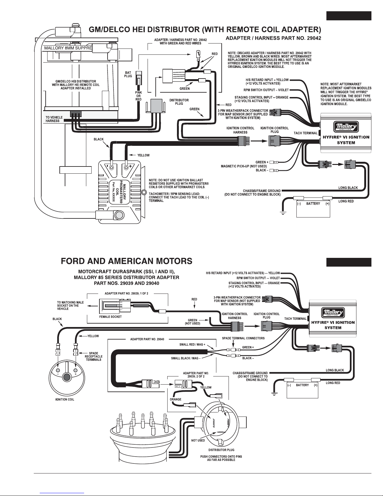
Connecting to Ford DuraSpark Systems (non-computer type) using Adapter PART
NO. 29039 and Harness PART NO. 29040 for OEM magnetic pickup
Refer to Figure 8 while performing the following steps.
Connecting Adapter PART NO. 29039:
• Disconnect all connectors at the ignition module, ignition coil and distributor. Remove
the ignition module. Remove the distributor and coil harnesses.
• Connect theAdapter ORANGE WIRE to the distributor plug’s ORANGE WIRE.
• Connect theAdapter YELLOW WIRE to the distributor plug’s PURPLE WIRE.
• Connect the other Adapter female socket to the vehicle’s matching male socket.
(The matching male socket was originally connected the ignition module.)
Connecting the Harness PART NO. 29040:
• Connect the HYFIRE®VI Electronic Ignition Control’s SMALL GREEN WIRE to the
Harness RED WIRE.
• Connect the HYFIRE®VI Electronic Ignition Control’s SMALL BLACK WIRE to the
Harness BLACK WIRE.
• Connect the mating plug of the Harness to the mating plug of theAdapter Part No. 29039
from the distributor.
Connecting the Ignition Control Harness:
• Route the Ignition Control Harness to the coil so that its wires do not make contact with
extreme heat, sharp objects or moving devises such as fans, belts and linkages.
• Crimp the Ignition Control Harness RED WIRE to the slice connector on theAdapter Part
No. 29039 female socket.
• Crimp a spade receptacle terminal on the Ignition Control Harness YELLOW WIRE.
Connect the YELLOW WIRE to the ignition coil (+) terminal. DO NOT allow any wire
except the YELLOW WIRE to make contact with the coil (+) terminal.
• Crimp a spade receptacle terminal on the Ignition Control Harness BLACK WIRE.
Connect the BLACK WIRE to the ignition coil (–) terminal.
• NOTE: Do not connect the GREEN WIRE of the Ignition Control Harness to anything.
Tape the end of the wire to insulate it.
• Go to Step 3, page 9.
Connecting to Early Model GM HEI Systems (non-computer type) using Adapter
PART NO. 29043 and Harness PART NO. 29040 for OEM magnetic pick-up. Refer to
Figures 11 and 12 while performing the following steps.
Connecting Adapter PART NO. 29043:
For coil-in-cap distributors only
• Disconnect the (RED or PINK) BAT PLUG/wire from the distributor cap.
• Disconnect the tachometer wire from the TACH terminal on the distributor cap.
• Disconnect the distributor plug from the distributor cap. For coil-in-cap distributors
and external coil
• Remove the distributor cap.
• Disconnect the pickup plug from the ignition module.
• Remove the ignition module, radio noise filter/capacitor and distributor plug harness.
• Slide theAdapter ORANGE and YELLOW WIRES through the grommet (supplied).
• Connect theAdapter ORANGE WIRE to the pickup plug’s WHITE WIRE.
• Connect theAdapter YELLOW WIRE to the pickup plug’s GREEN WIRE.
• Position the grommet into the slot on the edge of the distributor housing. Use cable ties
and 8-32 screws to hold wires in place.
• Install the distributor cap.
Connecting the Harness PART NO. 29040:
• Connect the HYFIRE®VI Electronic Ignition Control’s SMALL GREEN WIRE to the
Harness RED WIRE.
• Connect the HYFIRE®VI Electronic Ignition Control’s SMALL BLACK WIRE to the
Harness BLACK WIRE.
• Connect the mating plug of the Harness to the mating plug of theAdapter Part No. 29043
from the distributor.
Connecting the Ignition Control Harness:
• Route the Ignition Control Harness to the coil so that its wires do not make contact with
extreme heat, sharp objects or moving devises such as fans, belts and linkages.
• Crimp a spade terminal on the Ignition Control Harness RED WIRE.
For coil-in-cap distributors only
Refer to Figure 10 while performing the following steps.
• Connect the BAT PLUG/wire to the RED WIRE.
• Crimp the YELLOW WIRE to the YELLOW WIRE of the Adapter Part No. 29043
3-pin connector.
• Crimp the BLACK WIRE to the BROWN WIRE of the Adapter Part No. 29043
3-pin connector.
• Plug theAdapter Part No. 29043 3-pin connector into the distributor cap.
• Note: DO NOT connect the GREEN WIRE of the Ignition Control Harness to anything.
Tape the end of it to insulate it.
• Go to Step 3, page 9.
For external coil only
Refer to Figure 11 while performing the following steps.
(Replace the words “spade receptacle terminal” with “ring terminal” when
aftermarket coils with post type terminals are used.)
• Disconnect the BAT wire from the ignition coil BAT/(+) terminal. Connect the BAT wire to
the RED WIRE.
• Disconnect the tachometer wire from the ignition coil TACH/(–) terminal.
• Crimp a spade receptacle terminal on the Ignition Control Harness YELLOW WIRE.
Connect the YELLOW WIRE to the ignition coil BAT/(+) terminal. DO NOT allow any wire
except the YELLOW WIRE to make contact with the ignition coil BAT/(+) terminal.
• Crimp a spade receptacle terminal on the Ignition Control Harness BLACK WIRE.
Connect the BLACK WIRE to the ignition coil BAT/(–) terminal.
• Discard the adapter plug with the yellow and brown wires from the Adapter PART NO.
29043. It is not used on external ignition coil HEI systems.
•Note: DO NOT connect the GREEN WIRE of the Ignition Control Harness to
anything. Tape the end of it to insulate it.
• Go to Step 3, page 9.
Connecting to Mopar/Chrysler Electronic Systems (non-computer type) using
Harness PART NO. 29040 for OEM magnetic pickup
Refer to Figure 12 while performing the following steps.
• Disconnect all connectors at the ignition module, ignition coil and distributor. Remove the
ignition module. Take notice of a DARK GREEN/RED WIRE connected to the ignition
ballast resistor. Remove the distributor and coil harnesses.
Connecting the Harness PART NO. 29040:
• Connect the HYFIRE®VI Electronic Ignition Control’s SMALL GREEN WIRE to the
Harness RED WIRE.
• Connect the HYFIRE®VI Electronic Ignition Control’s SMALL BLACK WIRE to the
Harness BLACK WIRE.
• Connect the mating plug of the Harness to the distributor plug.
Connecting the Ignition Control Harness:
• Route the Ignition Control Harness to the ignition coil so that its wires do not
make contact with extreme heat, sharp objects or moving devices such as fans, belts
and linkages.
• Connect the RED WIRE to the terminal on the ignition ballast resistor that previously
had the DARK GREEN/RED WIRE connected to it (or to a 12-volt wire from the ignition
switch). NOTE: The RED WIRE must get voltage when the ignition switch is in the
START and RUN positions.
• Connect the YELLOW WIRE to the ignition coil (+) terminal. DO NOT allow any wire
except the YELLOW WIRE to make contact with the ignition coil (+) terminal.
• Connect the BLACK WIRE to the ignition coil (–) terminal.
• DO NOT connect the GREEN WIRE of the Ignition Control Harness to anything. Tape
the end of it to insulate it.
• Go to Step 3, page 9.
6

MAGNETIC PICKUP/CRANK TRIGGER COLOR CODES
BRAND/TYPE MAG+ MAG–
MALLORY CRANK TRIGGER PURPLE GREEN
MALLORY BILLET COMPETITION DISTRIBUTOR,
SERIES NOS. 81 AND 84 ORANGE PURPLE
MALLORY COMP 9000®SERIES NOS 96-99 ORANGE PURPLE
MALLORY HARNESS PART NO. 29040 RED BLACK
MSD™ CRANK TRIGGER PURPLE GREEN
MSD™ CRANK TRIGGER (OLD STYLE) ORANGE BLACK
MSD™ DISTRIBUTOR ORANGE PURPLE
MOROSO™ CRANK TRIGGER BLACK WHITE
ACCEL®CRANK TRIGGER BLACK WHITE
CHRYSLER ELECTRONIC DISTRIBUTOR ORANGE BLACK
FORD DURASPARK DISTRIBUTOR ORANGE PURPLE
DELCO/GM HEI DISTRIBUTOR WHITE GREEN
(2b) Wiring method without adapters; all breaker point distributors;
Mallory Electronic Ignitions (three wire/red, brown, green); OEM
electronic ignition amplifi ers.
Refer to: Figure 13 for breaker point distributors; Figure 15 for Mallory UNILITE®
Distributors, Magnetic Breakerless Distributors or Electronic Advance Distributors
(three wire/red, brown, green); Figure 16 for OEM electronic ignition amplifiers
Connecting the Ignition Control Harness
• RoutetheIgnitionControlHarnesstotheignitioncoilsothatitswiresdonotmakecontactwith
extreme heat, sharp objects or moving devises such as fans, belts and linkages.
• Disconnect ALL wires located on the ignition coil (+) terminal. These include the wires from
the ignition switch/ignition ballast resistor, start/ignition bypass and any other wires normally
connectedto theignition coil(+) terminal. Connectthese wiresto theRED WIRE. NOTE: The
RED WIRE must get voltage when the ignition switch is in the START and RUN positions.
If you are using a Mallory Electronic Ignition, connect its BROWN WIRE to engine ground
and add its RED WIRE to the Ignition Control Harness RED WIRE. Use Ring Terminal
Connectors to join wires together (See page 2 - Ignition Ballast Resistor / Loom Resistance
Wire and Standard Ignition Bypass).
• Similarly, disconnect ALL wires located on the ignition coil (–) terminal. Connect these wires
to the GREEN WIRE. If you are using a Mallory Electronic Ignition, add its GREEN WIRE
to the Ignition Control Harness GREEN WIRE. Use Ring Terminal Connectors to join
wires together.
• Connect the YELLOW WIRE to the ignition coil (+) terminal. DO NOT allow any wire
except the YELLOW WIRE to make contact with the ignition coil (+) terminal.
• Connect the BLACK WIRE to the ignition coil (–) terminal.
• Go to Step 3, page 9.
RING TERMINAL CONNECTORS:
Furnished with the HYFIRE®VI Electronic Ignition Controls are two Ring Terminal Connectors
for the convenience of getting a neat installation when the HYFIRE®VI Electronic Ignition
Control is added to an existing ignition system. These Ring Terminal Connectors allow the
existing ignition system wiring to remain in the area of the ignition coil.
• Move wires onto the stud that is inside the Ring Terminal Connector body.
• Secure these wires to the stud with the nut and washer.
• Install the Ring Terminal Connector cap.
(2c) Wiring Method without adapters for Magnetic Pickup Trigger
Pulses (Non-Computer Type); Magnetic Pickup Distributors or
Crank Trigger Ignition
Connecting to Magnetic Pickup Distributors and Crank Trigger Ignition – Refer to
Figure 17.
• Connect the magnetic pickup (+) wire to the SMALL GREEN WIRE from the HYFIRE®VI
Electronic Ignition Control.
• Connect the magnetic pickup (–) wire to the SMALL BLACK WIRE from the HYFIRE®VI
Electronic Ignition Control.
Connecting the Ignition Control Harness:
• Route the Ignition Control Harness to the ignition coil so that its wires do not make contact
with extreme heat, sharp objects or moving devises such as fans, belts and linkages.
• Connect the RED WIRE to the 12-volt wire from the ignition switch. NOTE: The RED
WIRE must get voltage when the ignition switch is in the START and RUN positions. Use
a Ring Terminal Connector to join wires together.
• Connect the YELLOW WIRE to the ignition coil (+) terminal. DO NOT allow any wire
except the YELLOW WIRE to make contact with the ignition coil (+) terminal.
• Connect the BLACK WIRE to the ignition coil (–) terminal.
• DONOT connectthe GREEN WIRE of the Ignition Control Harness to anything. Tapethe
end of it to insulate it.
• Go to Step 3, Page 9.
FIGURE 10
7

ABCD
LONG BLACK
®
®
FIGURE 10
FIGURE 11
8

®
FIGURE 12
®
FIGURE 13
Step 3
Tachometer Operation:
If a tachometer is used, connect tachometer ignition sensing lead to the TACH terminal on the
HYFIRE®VI Electronic Ignition Control.
If the tachometer does not work after being connected to the TACH terminal, connect the
tachometer ignition sensing lead to the GREEN WIRE from the Ignition Control Harness. If
this does not work, your tach is a high voltage trigger tach and will require the Mallory Fuel
Injection and Tachometer Adapter Part No. 29074 or 29078 to supply the proper signal for
the tachometer to operate.
Step 4
Secure all wires with cable ties to prevent contact extreme heat, sharp objects or moving
devices such as fans, belts and linkages.
Step 5
Recheck all wire and connections to ensure they are correct before applying power.
Step 6
Connect the battery (–) terminal cable. Start engine and check operation of the ignition system.
®
FIGURE 15
TACH/RPM OUTPUT
9

®
FIGURE 16
®
FIGURE 17
®
FIGURE 15
10

Top Panel Operation and Features
Mallory HYFIRE®VI 685 CD Ignition System
The Mallory HYFIRE®VI 685 ignition system has a number of features that are set up by using
the top panel display and switches. Here is a list of the different features (or modes):
Mode 1 – This is the normal engine protection RPM limit. It is active if no other RPM limit is
selected. The range of this limiter is 1000 to 12800 in steps of 100 RPM.
Mode 2 – This is the auxiliary RPM limiter, and it is activated when 12 volts is applied to the
ORANGE wire coming out of the end panel. The range is the same as the Mode 1 RPM
limiter. This RPML will over-ride the Mode 1 RPML when it is active.
Mode 3 – This is a selectable high-speed timing retard. It is selected when the YELLOW
wire coming out of the end panel has 12 volts applied. The range is 1 to 15 degrees in .1
degree steps.
Mode 4 – Start retard value. This amount of retard is applied whenever the engine RPM is
below 500. The range is .1 to 10 degrees in .1 degree steps.
Modes 5 and 6 – These two control the built-in RPM activated “window” switch. Mode 5
sets the RPM where the switch activates, and mode 6 sets the RPM where the switch
de-activates. This is useful if, for example, you want to have your nitrous system only
work within a certain RPM range. The output wire for the RPM switch is the VIOLET wire
coming out of the end panel. It is connected to ground when the switch is active, and has
a maximum current rating of 10 amps. NOTE: The RPM range for this switch is 1000 to
12, 8000 and the off RPM (mode 6) must be at least 100 RPM higher than the on RPM
(mode 5).
Mode 7 – Tach test. This feature allows you to check the accuracy of your tachometer
and any accessories connected to the tach output terminal. It also will activate the built-in
RPM switch in the Hyfire. To use the tach test feature, turn the ignition switch on without
starting the engine. Select mode 7. Turn the ignition switch off briefly, then back on again.
The HYFIRE®will be generating a signal at the tach output terminal at the RPM displayed
on the top panel. You can use the UP and DOWN arrow keys to change the RPM to the
desired value.
To return to normal operation, select mode 1. Turn the ignition switch off. The next time the
ignition switch is turned on, the HYFIRE®will be out of the tach test mode.
Mode 8 – Boost timing retard degrees per PSI of boost. If you have an optional MAP sensor
connected, the HYFIRE®685 will retard the timing as the boost pressure increases. Mode 8
tells the system how many degrees to retard the timing for each pound of boost. The MAP
sensor plugs into the 3 wire connector that comes out of the front panel. If you don’t have a
MAP sensor installed, this function has no effect.
Mode 9 – Cylinder number select. Set this to however many cylinders your engine has. The
range is 3 to 12, even-fire ONLY!
Mode A – MAP sensor select. There are two MAP sensors available that are compatible
with the HYFIRE®685. One is a 2 Bar sensor (Accel P/N 74776), which is good for about
15 PSI of boost, and the other is a 3 Bar sensor (Accel P/N 74777), good for about 30 PSI
of boost. Use modeAto tell the HYFIRE®685 which sensor you are using. If you don’t have
a MAP sensor installed, this function has no effect.
To use the boost retard feature, you must use the Mallory P/N 29785 harness and
appropriate MAP sensor, as referenced above. Both the harness and the MAP sensors are
available separately.
BYPASS CONNECTOR
The Bypass Connector (standard ignition bypass) fits into the mating plug of the Ignition
Control Harness to convert back to standard ignition. If you use the Bypass Connector,
use ignition ballast resistors designed for the particular distributor and coil in the wire from
the ignition switch. DO NOT put the Bypass Connector into the mating plug of a Mallory
HYFIRE®VI RPM Limiting Adapter, or Single or Multi Stage High Speed Retard. DO NOT
put the Bypass Connector into the mating plug of a Mallory Electronic Advance Computer
or Remote Timing Control. Use the Power Plug to convert back to standard ignition. Also, if
you are using a Mallory Fuel Injection/Tachometer Adapter (Part No. 29074), disconnect it
(and its diode if used) as part of converting back to standard ignition. The Bypass Connector
(standard ignition bypass method to convert back to standard ignition) does not work with
magnetic pickup distributors or crank trigger ignition.
FIGURE 20
MODE
MODE
VALUE
MICROPROCESSOR CONTROLLED CD IGNITION SYSTEM
A. MAP SENSOR
9. CYLINDER NUMBER
8. BOOST DEG/PSI
7. TACH TEST
6. RPM SWITCH HIGH
5. RPM SWITCH LOW
4. START RETARD
3. SELECTABLE RETARD
2. AUX RPML
1. MAIN RPML
PART No. 685
RR
®
PUSH THESE TO
RAISE OR LOWER
THE SELECTED
MODE VALUE THIS WILL BLINK
DURING CRANKING
IF THE TRIGGER
SIGNAL IS PRESENT
PUSH THIS BUTTON TO
SELECT THE MODE
FIGURE 19
11

X100X1000
6 4
CYL
PART No. 6851
RPM
MICROPROCESSOR CONTROLLED CD IGNITION SYSTEM
RR
®
HYFIRE®6851 IGNITION SYSTEM
The Mallory HYFIRE®6851 ignition system has the same basic connections as the 685
ignition system. However, the only accessory included is an RPM activated switch. This
RPM switch is controlled by two rotary DIP switches that are located behind an access plate
on the top of the unit (see the illustration below). Loosen the two screws to gain access to
the switches.
You can select 4 or 6 cylinder operation, and an RPM switch value from 1000 to 9900 RPM.
Use a small screwdriver or similar to select 4 or 6 cylinder mode, if desired. If both these
switches are off, the unit is in 8 cylinder mode. Use a screwdriver to set the 1000 RPM and
100 RPM switches to the desired setting. When you reach this RPM, the violet wire coming
out of the end panel will be connected to ground (10 amp maximum).
OPTIONAL IGNITION ACCESSORIES
Multi Stage High Speed Retard – Part No. 618-3
This is a finger tip adjustable 3-stage timing retard control with an adjustment range for
the first and second stage of 0°-15° and a range of 0°- 20° for the third stage. Each
succeeding stage overrides the previous stage to allow you to reduce (or add) ignition timing
on a succeeding stage. This retard is designed to be easily added to the HYFIRE®VI
Electronic Ignition Control.
Mallory Electronic Advance Computer – Part Nos. 600-04, 600-06 and 600-08
This is a user programmable advance curve system using a CMOS microprocessor for
advance calculations. This allows you to select from 256 different advance curve
combinations! It is designed with matching mating plugs so it can to be added between the
HYFIRE®VI Electronic Ignition Control and the Ignition Control Harness.
Mallory Remote Timing Control – Part No. 631
Mallory’s Remote Timing Control allows you to change the ignition timing as you drive for
maximum performance, for better fuel economy or to avoid engine knock.
NOTE: The accessories listed above will not work properly with odd-fire V6
applications or point trigger distributors. They are not designed for marine use.
Mallory Fuel Injection and Tachometer Adapter – Part No. 29074 and 29078
Some applications with fuel injection or a tachometer need a voltage spike signal from the
negative side of the coil before they will operate properly. This signal changes once the
HYFIRE®VIElectronic IgnitionControlis installed.Mallory’sadapter providesthe proper signal
to trigger most fuel injection systems and voltage/current triggered tachometers.
FIGURE 21
12

TROUBLESHOOTING GUIDE FOR
CAPACITIVE DISCHARGE
(CD) IGNITION SYSTEMS
Most CD boxes operate the same way, making for
common basic test procedures. Most CD ignition
boxes have two separate triggering circuits in them.
One is for a regular points driver signal, which is a
square wave, and one for 2 wire magnetic, which is
a sine wave, and the two have slightly different
test procedures.
Before beginning any testing, start with the basics.
Using your ignition instructions as a guide, recheck all
of the connections and terminals, and make sure the
wires are routed correctly and are free from abrasions
or other damage. Some ignitions also are equipped
with indicator lights that can check the power source
and some internal circuits.
IGNITION BOXES USING SINGLE WIRE POINTS
TYPE TRIGGERING
If the box powers up but does not fire the coil and the
white wire is being used as the trigger source, the
following tests should be done:
1. With the key off, remove the coil wire from
distributor cap and get it where you can jump a
spark to the block, with a gap of about 1/2 inch.
Separate the triggering wire that connects the box
and the distributor together, the wire colors will
differ between boxes and distributor combinations,
for example: MSD, Crane, ACCEL and Mallory
boxes are white. On the Mallory Hyfire I’s to IV’s
and the new Hyfire VI (6) P/N 685, this wire is green.
Refer to your ignition’s instruction sheet to confirm
the color of the wire.
2. Turn the ignition switch to the "ON" position. While
holding the coil wire close to the engine block, tap
the white wire to an engine ground. This will trigger
the box and should fire the coil, jumping a spark to
ground through the coil wire. If there is no spark
from the coil wire and no audible snap comes from
the box, the box is bad. If you hear a snap in the
box but no fire at the coil wire, then the coil or the
coil wire could be bad and they need to be tested.
3. If the test comes out positive and the box, coil and
coil wire are working, the distributor is either not
working or is improperly wired into the system and
the installation instructions should be revisited.
IGNITION BOXES USING TWO WIRE MAGNETIC
TYPE TRIGGERING
1. With the key off, remove the coil wire from the
distributor and position the wire so a spark can be
jumped to the block, with a gap of about 1/2 inch.
Disconnect the 2 magnetic wires from the box and
lay them aside. Next take a short piece of wire and
bend it in the shape of a "U". This wire will be used
to short the 2 wires of the magnetic connector on
the box together.
2. With the key in the "ON" position, the coil wire
where you can jump a spark to the engine block,
and using the "U" shaped wire you have made up,
short the two wires in the connector of the box
together and then disconnect the shorting wire.
3. ach time you disconnect the shorting wire the box
should fire the coil and should jump a spark to
ground. If the coil does not fire then either the
magnetic circuit in the box is inoperative or the coil
or coil wire are bad. Magnetic distributor pickups
are generally 400 to 650 ohms of resistance. If it is
a crank trigger, the pickup is rated at about 80
ohms resistance.
4. With any of the larger MSD, Crane, and Mallory 7
and 8 boxes the tests are similar. The difference is
that they have a terminal strip instead of a wire
harness but have the same two circuits in them
and test as follows.
5. To test the magnetic circuit in the box simply
disconnect the two wire from the "MAG + and
MAG –" terminal on the box. Connect a short piece
of wire to one of the terminals. With the key on and
coil wire ready to jump a spark to the block, rapidly
tap the other end of the short jumper wire to the
other magnetic terminal. The box should fire
the coil.
6. If the trigger is points or Unilite then disconnect the
distributor from the box. Connect a long piece of
wire to the "Points" terminal of the box. With the
key on, rapidly tap this wire to ground and the box
should fire the coil.
13

7. If both of these tests prove out, then the problem is
either in the distributor, crank trigger, or the wiring
is incorrect.
TESTING THE COIL
NOTE: This test should only be done on "stock type"
coils. DO NOT try this test with "CD Only" coils, such
as the Mallory 28880 or ACCEL 140019 and 140010.
This test is also helpful in testing the coil when used
with just a distributor and you are having a "No
Spark" to the plugs condition. When doing this test
you must disconnect the distributor from the coil (-)
terminal, taking it out of the loop and allowing the test
to be done properly.
1. Disconnect the wires coming from the CD box to
the coil (+ and -) terminals and connect the ignition
switch 12 volts wire to the coil (+) terminal of
the coil.
2. Connect a 24" piece of wire to the coil (-) of
the coil.
3. Pull the coil wire out of the distributor cap and get
it to where you can jump a spark to ground with it.
4. Turn the ignition to the "ON" position.
5. Rapidly tap the 24" wire to ground. This will fire the
coil. You should get a 1/4” to 3/8" spark out of the
high voltage coil wire to ground. If you do then the
coil and coil wire are good and working.
6. If no spark to ground, change out the coil wire and
do the test again. If still no spark, the coil is bad
and needs to be replaced.
14
Table of contents
Other Mallory Control Unit manuals