Mallory 609 User manual
0
®
INSTALLATION INSTRUCTIONS
FORM 1356 (REV. C) 2/00
MAGNETIC BREAKERLESS
IGNITION MODULE
PART NO. 609
APPLICATION: YLM and YTM Series Distributors; 50 Series Mechanical Advance Distributors; 57 Series
Vacuum Advance Distributors; 82 Series Mechanical Advance Billet Competition Distributors; COMP
9000®87 Series Vacuum Advance Distributors; COMP 9000®89 Series Mechanical Advance Distribu-
tors; Magnetic Breakerless Ignition Conversions.
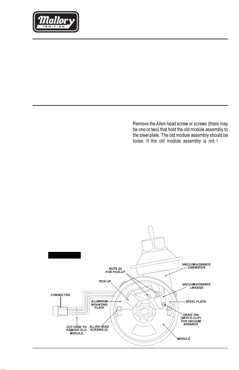
CONNECTOR
CUT HERE TO
REMOVE OLD
MODULE
ALUMINUM
MOUNTING
PLATE
PICK-UP
NUTS (2)
FOR PICK-UP
VACUUM ADVANCE
CANNISTER
VACUUM ADVANCE
LINKAGE
STEEL PLATE
DRIVE PIN
(WITH E-CLIP)
FOR VACUUM
ADVANCE
ALLEN HEAD
SCREWS (2)
MODULE
Remove the Allen head screw or screws (there may
be one or two) that hold the old module assembly to
the steel plate. The old module assembly should be
loose. If the old module assembly is not loose,
remove the two magnetic pickup nuts on the old
module assembly. See Figure 1.
Series 82 and 89 Distributors
Remove the two Allen head screws that hold the old
module assembly to the steel plate. The old module
assembly should be loose. If the old module assem-
bly is not loose, remove the two magnetic pickup
nuts on the old module assembly. See Figure 1.
Step 3
Lift the old module assembly up and out of the
distributor housing.
INSTALLATION PROCEDURE
Step 1
Remove the distributor cap and rotor (NOTE: On
Series Nos. 82, 87 and 89 Distributors, also remove
the adapter shield). Unplug the old module (female
connector) from the distributor wire harness. Cut the
female connector off the end of the wires from the old
module assembly and push the wires through the
grommet. See Figure 1.
Step 2
YLM and YTM Series, and 50 Series
Distributors
Loosen (do not remove) the two nuts on the side of
the distributor housing.
Series 57 and 87 Distributors
Remove the small E-clip that holds the vacuum
advance linkage on the drive pin on the steel plate.
Lift the vacuum advance linkage off the drive pin.
FIGURE 1
2
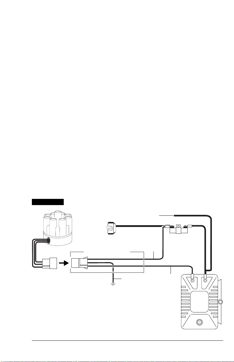
INDEX RIB
RED
BROWN
GREEN
RED
BROWN
GREEN
FEMALE
CONNECTOR
DISTRIBUTOR WIRE
HARNESS
FIGURE 3
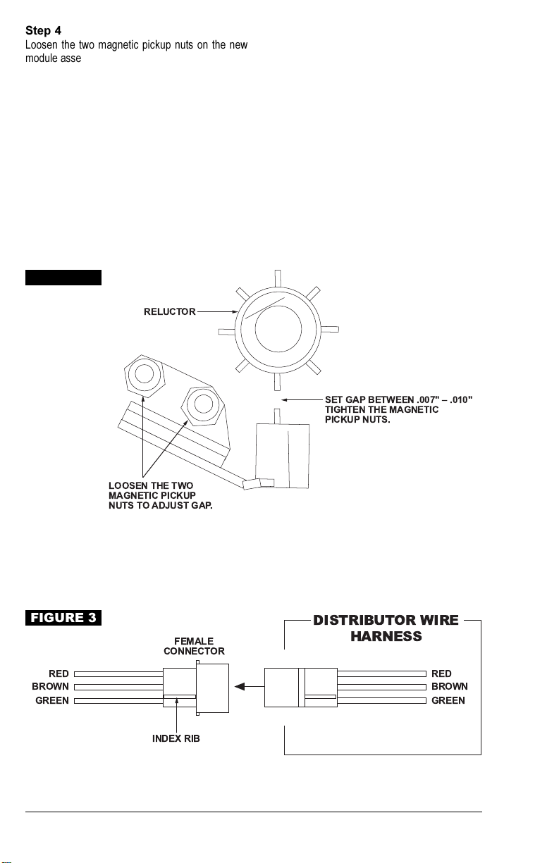
Step 4
Loosen the two magnetic pickup nuts on the new
module assembly. See Figure 2.
NOTE (57, 82, 87 and 89 Series Distributors): If
you had to remove the two magnetic pickup
nuts that hold the pickup to the old module
assembly (Step 2), remove the two magnetic
pickup nuts on the new module assembly and
press the two studs out of the new module
assembly. Discard these nuts and studs.
Step 5
Install the new module assembly in the reverse
order from the way the old module assembly was
removed (Steps 2 and 3).
Step 6
Set the magnetic pickup gap between 0.007-0.010"
when tooth on the reluctor is pointing directly at the
center of the metal pole on the magnetic pickup. A
0.0074" polyester gauge is provide to help in setting
the magnetic pickup gap. Tighten the two nuts that
hold the magnetic pickup to the new module as-
sembly. See Figure 2.
Step 7
Slide the three wires from the module assembly
through the grommet, to outside the distributor
housing. Put the three wires in the female connec-
tor: GREEN WIRE in hole #1; BROWN WIRE in
hole #2; RED WIRE in hole #3; Plug the female
connector into the distributor wire harness. See
Figure 3.
RELUCTOR
SET GAP BETWEEN .007" .010"
TIGHTEN THE MAGNETIC
PICKUP NUTS.
LOOSEN THE TWO
MAGNETIC PICKUP
NUTS TO ADJUST GAP.
TO SET MAGNETIC
PICKUP GAP:
FIGURE 2
2
REVIEW WIRING
PROCEDURE
IMPORTANT: Make sure that your vehicle is
equipped with an ignition ballast resistor (or loom
resistance wire) in the wire between the ignition
switch and the coil (+) terminal. One easy way to find
the ignition ballast resistor is to check the service
manual for your vehicle. You can test your ignition
system voltage while the engine is at idle at the coil
(+) terminal. If the measured voltage is within 1-volt of
battery voltage, an ignition ballast resistor must be
installed in the wire from the ignition switch.
Example: Vehicles with a Ford TFI or Delco HEI
require adding an ignition ballast resistor in the wire
from the ignition switch. If you find your vehicle is
not equipped with an ignition ballast resistor, install
a Mallory Ignition Ballast Resistor Part No. 700 in
series in the wire from the ignition switch. Failure to
use an ignition ballast resistor will result in the
eventual destruction of the module.
Exception: If your vehicle is equipped with a
HYFIRE®Electronic Ignition Control or similar after-
market ignition control, use ignition ballast resistors
and wiring procedures as stated in the instructions
for the particular ignition control.
DISTRIBUTOR WIRE
HARNESS
RED Power/voltage for the module
Connect to ignition switch
GREEN Ignition trigger
Connect to coil () terminal
BROWN Ground for the module
Connect to engine block ground
NOTE: If your vehicle is equipped with a
HYFIRE®Electronic Ignition Control or similar
aftermarket ignition control, use ignition ballast
resistors along with wiring procedures included
with your ignition control.
+
COIL
–
ALL OTHER WIRES ORIGINALLY CONNECTED
TO THE COIL(+) TERMINAL
FIGURE 4
12V/IGNITION
SWITCH
DISTRIBUTOR WIRE HARNESS
PART NO. 29349
IGNITION MODULE
FEMALE CONNECTOR ENGINE
GROUND
BROWN GREEN
RED
IGNITION BALLAST
RESISTOR
NOTE: The purpose of an ignition ballast resistor
between the ignition switch (12V) and the ignition coil
positive terminal is to restrict current flow through the
ignition coil. Failure to use an ignition ballast resistor
will eventually destroy the Ignition Module.
EXCEPTION: If your vehicle is equipped with a HYFIRE®
Electronic Ignition Control or similar aftermarket ignition
control, use the wiring procedures stated in the
instructions included with the ignition control
To prevent false triggering and possible premature
ignition failure, you must use suppression type (carbon
core, spiral core, or radio suppression core) spark plug
wire.
DO NOT USE SOLID CORE (COPPER CORE OR
STAINLESS STEEL CORE) SPARK PLUG WIRE WITH
ANY ELECTRONIC IGNITION SYSTEM.
WIRING WITH BALLAST RESISTOR

4
MALLORY IS A DIVISION OF THE MR. GASKET PERFORMANCE GROUP
550 MALLORY WAY, CARSON CITY, NV 89701
(775) 882-6600 FAX (775) 887-4326
www.mrgasket.com
FORM 1356
REV. C (2/00)
MADE IN U.S.A.
PRINTED IN U.S.A.
FIGURE 5
COIL
–
+
ALL OTHER WIRES ORIGINALLY CONNECTED
TO THE COIL (+) TERMINAL
12V/IGNITION
SWITCH
DISTRIBUTOR WIRE HARNESS
PART NO. 29349
IGNITION MODULE
FEMALE CONNECTOR
ENGINE
GROUND BROWN
GREEN
RED
LOOM RESISTANCE WIRE
NOTE: The purpose of loom resistance wire between
the ignition switch (12V) and the ignition coil positive
terminal is to restrict current flow through the ignition
coil. Failure to use an ignition ballast resistor will
eventually destroy the Ignition Module.
EXCEPTION: If your vehicle is equipped with a HYFIRE®
Electronic Ignition Control or similar aftermarket ignition
control, use the wiring procedures stated in the
instructions included with the ignition control.
To prevent false triggering and possible premature
ignition failure, you must use suppression type (carbon
core, spiral core, or radio suppression core) spark plug
wire.
DO NOT USE SOLID CORE (COPPER CORE OR
STAINLESS STEEL CORE) SPARK PLUG WIRE WITH
ANY ELECTRONIC IGNITION SYSTEM.
WIRING WITH LOOM RESISTANCE WIRE
Table of contents
Other Mallory Control Unit manuals


Popular Control Unit manuals by other brands

Festo
Festo Compact Performance CP-FB6-E Brief description

Elo TouchSystems
Elo TouchSystems DMS-SA19P-EXTME Quick installation guide

JS Automation
JS Automation MPC3034A user manual

JAUDT
JAUDT SW GII 6406 Series Translation of the original operating instructions

Spektrum
Spektrum Air Module System manual

BOC Edwards
BOC Edwards Q Series instruction manual

KHADAS
KHADAS BT Magic quick start

Etherma
Etherma eNEXHO-IL Assembly and operating instructions

PMFoundations
PMFoundations Attenuverter Assembly guide

GEA
GEA VARIVENT Operating instruction

Walther Systemtechnik
Walther Systemtechnik VMS-05 Assembly instructions

Altronix
Altronix LINQ8PD Installation and programming manual


