Mallory 605 User manual

Ignition Module
Instruction Manual
Part#: 605, 609

INSTALLATION AND ELECTRICAL WIRING PROCEDURE
PN 605/UNILITE®MODULE: Apply a thin coat of silicone grease to the
bottom of the module before mounting the module to its plate in the dis-
tributor.
PN 609 and PN 605: Slide the three wires from the MODULE, through
the grommet, to outside the distributor housing. Put the three wires from
the MODULE in the TERMINAL PIN HOUSING: GREEN WIRE in hole
#1, BROWN WIRE in hole #2, RED WIRE in hole #3.Plug the three wire
harness (PN 29349, not supplied with this kit) into the TERMINAL PIN
HOUSING.
WARNING: Make sure that the vehicle is originally equipped from
the factory with an ignition ballast resistor or loom resistance wire
from the ignition switch to the coil (+) terminal. If the vehicle is not
originally equipped from the factory with an ignition ballast resistor
or loom resistance wire, a Mallory ballast resistor, PN 700, must be
installed in series on the wire from the ignition switch to the coil (+)
terminal. See a service manual for the vehicle for further information.
For example, vehicles equipped with Ford TFI, or Delco HEI ignition
require the installation of a Mallory ballast resistor, PN 700.Failure to
use a resistor will result in the eventual destruction of the module.
®
IGNITION MODULE PN 605 and PN 609
Reluctor
Set gap (between .007" – .010")
when a tooth on the reluctor is
pointing directly at the center of
the metal pole on the magnetic
pickup. Tighten the magnetic
pickup mounting nuts.
To set pickup gap:
Loosen the two magnetic
pickup mounting nuts.
A .0075" polyester gauge is provided to assist in setting the pickup gap.
Connect the three wires as follows:
If a HYFIRE®or other aftermarket ignition control is being used, connect
the MODULE according to the instructions supplied with the HYFIRE®or
aftermarket ignition control.
RED WIRE: Power/voltage for the MODULE.Connect to coil (+) terminal.
GREEN WIRE: Ignition trigger. Connect to coil (–) terminal.
BROWN WIRE: Ground for the MODULE. Connect to ENGINE BLOCK
GROUND. Clean away any grease, oil, and paint from the
mounting surface before the connection is made.
COIL
+
–
12 3
+12V FROM IGNITION SWITCH
GROUNDTO ENGINE BLOCK
IGNITION BALLAST RESISTOR RED
GREENBROWN
COIL
+
–
12 3
+12V FROM IGNITION SWITCH
GROUNDTO ENGINE BLOCK
LOOM RESISTANCE WIRE
RED
GREEN
BROWN
NOTE—
When using a HYFIRE®or
other aftermarket ignition
control, connect the MODULE
according to the instructions
supplied with the HYFIRE®or
aftermarket ignition control.
NOTE—
If your vehicle is difficult to
start, remove the red wire
from the plus (+) side of the
ignition coil and connect it
to the ignition switch side of
the ballast resistor.
Mallory-Ignition.com
1

PROCÉDURE D’INSTALLATION ET DE CÂBLAGE ÉLECTRIQUE
MODULE Pièce N° 605/UNILITE®:Appliquer une mince couche de
graisse de silicone sur la base du module d’allumage avant de monter
le module sur sa plaque dans le distributeur.
Pièce N° 609 et Pièce N° 605 : Faire glisser les trois câbles qui
proviennent du MODULE, à travers le passe-câble à l’extérieur du carter
de l’allumeur. Mettre les trois câbles du MODULE dans le PLOT du
CARTER : le CÂBLE VERT dans le trou n° 1, le CÂBLE BRUN dans le
trou n° 2, le CÂBLE ROUGE dans le trou n° 3. Brancher les trois
faisceaux de câblage (Pièce N° 29349, pas fourni avec ce kit) dans le
PLOT du CARTER.
MISE EN GARDE : S’assurer que le véhicule était équipé, à sa sortie
d’usine, d’un système d’allumage antiparasite à ballast ou d’un câble
de résistance en faisceau entre le commutateur d’allumage et la
borne (+) de la bobine. Si le véhicule n’était pas équipé, à sa sortie
d’usine, d’un système d’allumage antiparasite à ballast ou d’un câble
de résistance en faisceau, une résistance ballast Mallory,
Pièce N°
700, doit être installée en série sur le câble entre le commutateur
d’allumage et la borne (+) de la bobine. Consulter le manuel de
réparation du véhicule pour plus de détails. Par exemple, les
véhicules équipés d’un système d’allumage Ford TFI ou Delco HEI
requièrent l’installation d’une résistance ballast Mallory,
Pièce N°
700. Le module pourrait être détruit si le véhicule n’est pas équipé
d’une telle résistance.
®
MODULE D’ALLUMAGE PIÈCE N° 605 et PIÈCE N° 609
Réluctance
Régler l’écartement (entre 0,17
mm et 0,25 mm (0,007 po et
0,010 po)) lorsqu’une dent de la
réluctance pointe directement
au centre du pôle de métal
du réglage magnétique.
Resserrer les écrous de
fixation du réglage magnétique.
Pour fixer le réglage de
l’écartement :
Desserrer les deux écrous
de fixation du réglage
magnétique.
Une jauge de polyester de 0,19 mm (0,0075 po) est fournie pour aider à
déterminer le réglage de l’écartement.
Brancher les trois câbles comme suit :
Si une commande d’allumage électronique HYFIRE®ou une autre com-
mande d’allumage de rechange est utilisée, brancher le MODULE selon
les instructions fournies avec la commande d’allumage.
CÂBLE ROUGE : Puissance/voltage pour le MODULE. Brancher à la borne
(+) de la bobine.
CÂBLE VERT : Générateur d’impulsion d’allumage. Brancher à la borne (-)
de la bobine.
CÂBLE BRUN : Mise à la terre pour le MODULE.Brancher à la masse, sur
le bloc moteur.Toujours nettoyer la surface de montage de
toute trace de graisse, d’huile ou de peinture avant d’ef-
fectuer les branchements.
BOBINE
+
–
1 2 3
+ 12 V DU COMMUTATEUR
D’ALLUMAGE
METTRE À LA MASSE,
SUR LE BLOC MOTEUR
SYSTÈME D’ALLUMAGE
ANTIPARASITE À BALLAST ROUGE
VERTBRUN
BOBINE
+
–
1 2 3
+ 12 V DU COMMUTATEUR
D’ALLUMAGE
METTRE À LA MASSE,
SUR BLOC MOTEUR
CÂBLE DE RÉSISTANCE
EN FAISCEAU ROUGE
VERT
BRUN
REMARQUE :
Lorsque qu’une commande
d’allumage électronique
HYFIRE®ou une autre
commande d’allumage de
rechange est utilisée,
brancher le MODULE selon
les instructions fournies avec
la commande d’allumage.
REMARQUE :
S’il est difficile de faire
démarrer votre véhicule,
enlever le câble rouge du
côté plus (+) de la bobine
d’allumage et le brancher à
la résistance à ballast du
côté du commutateur d’al-
lumage.
Mallory-Ignition.com
2

PROCEDIMIENTO DE INSTALACIÓNY CABLEADO ELÉCTRICO
NO. DE PIEZA 605/MÓDULO UNILITE®:Aplique una capa delgada de
grasa con silicona al fondo del módulo antes de montarlo en su placa
en el distribuidor.
NO. DE PIEZA 609 y NO. DE PIEZA 605: Deslice los tres cables que
vienen del MÓDULO a través del separador hasta la armazón del
distribuidor. Coloque los tres cables del MÓDULO en el TERMINAL DE
CLAVIJA DEL ARMAZÓN: EL CABLE VERDE en el orificio #1, EL
CABLE MARRÓN en el orificio #2, EL CABLE ROJO en el orificio #3.
Conecte las bridas de estos tres cables (NO. DE PIEZA 29349, no se
suministra con este juego) en el TERMINAL DE CLAVIJA DEL
ARMAZÓN.
ADVERTENCIA: Asegúrese de que el vehículo viene de fábrica
equipado con una resistencia de balasto del encendido o un cable de
resistencia fibroso flexible desde el interruptor de encendido al
terminal (+) de la bobina. Si el vehículo no ha venido originalmente
de fábrica con una resistencia de balasto o un cable de resistencia
fibroso flexible, se debe instalar una resistencia de balasto Mallory,
No. de pieza 700, en serie con el cable que va del interruptor del
encendido al terminal de la bobina (+). Si desea más información,
consulte el manual de servicio. Por ejemplo, los vehículos que
vienen con encendido TFI de Ford o HEI Delco requieren la
instalación de la resistencia de balasto Mallory, No. de pieza 700. Si
no se usa la resistencia, se puede destruir el módulo con el tiempo.
®
MÓDULO DE ENCENDIDO NO. DE PIEZA 605 y NO. DE PIEZA 609
Medidor de la reluctancia
Calibre el espacio (entre 0.007
y 0.010 pulgada) cuando un
dientedel medidor de reluctancia
esté apuntando directamente al
centro del poste metálico en
la captación magnética.
Ajuste las tuercas de montaje
de la captación magnética.
Para calibrar el espacio
de captación:
Afloje las dos tuercas de
montaje de la captación
magnética.
Se suministra un calibrador de poliéster de 0.0075 pulgada para
ayudar a calibrar el espacio de captación.
Conecte los tres cables de la siguiente forma:
Si se usa el control electrónico de encendido HYFIRE®u otro control
introducido en el mercado posteriormente, conecte el MÓDULO de
acuerdo con las instrucciones que vienen con el control de encendido.
CABLE ROJO: Corriente/voltaje para el MÓDULO.Conéctelo al terminal
(+) de la bobina.
CABLE VERDE: Disparador de encendido. Conéctelo al terminal (-) de la
bobina.
CABLE MARRÓN: Conexión a tierra para el MÓDULO. Conéctelo a tierra en
el bloque del motor. Antes de hacer la conexión, limpie
cualquier grasa, aceite y pintura que haya en la superfi-
cie de montaje.
BOBINA
+
–
1 2 3
+12V DEL INTERRUPTOR
DE ENCENDIDO
CONEXIÓN A TIERRA EN
EL BLOQUE DEL MOTOR
RESISTENCIA DE BALASTO
DEL ENCENDIDO ROJO
VERDEMARRÓN
BOBINA
+
–
1 2 3
+12V DEL INTERRUPTOR
DE ENCENDIDO
CONEXIÓN A TIERRA EN
EL BLOQUE DEL MOTOR
CABLE DE RESISTENCIA
FIBROSO FLEXIBLE ROJO
VERDE
MARRÓN
NOTA:
Si se usa el control electrónico
de encendido HYFIRE®u otro
control introducido en el
mercado posteriormente,
conecte el MÓDULO de
acuerdo con las instrucciones
que vienen con el control de
encendido.
NOTA:
Si tiene dificultad para
arrancar su vehículo, saque
el cable rojo del lado positivo
(+) de la bobina de encendido
y conéctelo en el lado de la
resistencia de balasto que
corresponde al interruptor
de encendido.
Mallory-Ignition.com
3

NOTE: IF YOU ARE USING A CD IGNITION BOX, YOU MUST BYPASS IT BEFORE PERFORMING THIS TEST!
®
UNILITE®TEST PROCEDURE
1) Remove the cap and rotor. Turn the ignition ON and test
voltage at the NEGATIVE side of the coil (black lead of
meter to ground and red lead of meter to coil NEGATIVE
post). Voltage should read 12 volts.
2) If battery voltage is present, place a credit card, drivers
license, business card or similar and block the photo
optics of the module. The voltage should drop to 2volts
or less (1 to 2 volts). If this test is positive, then the
module is working.
3) If the test results are as follows:
a) Voltage does not drop, module is open and must
be replaced. This may have been caused by a power
surge, high resistance in the plugs or plug wires, or
improper ground. Possible charging system load
dump.
b)Voltage always stays below 2. 0 volts. The module
has been spiked by high voltage or amperage, lack
of ballast resistor, or improperly wired.
c) Voltage only drops to 3-4 volts could produce a weak
spark.
Possible causes are:
Faulty charging system (stuck or shorted regula-
tor/alternator)
Faulty starting system (starter drag)
Non-suppression spark plug wires (copper or stain-
less core wires). Spark plug wires must be carbon
core or spiral wound plug wires.
Large amperage alternator
High amp stereo equipment
CB radio
Direct shorts in the ignition or electrical system
Trying to start motor with battery charger hooked
up
Welding on the vehicle with the distributor hooked
up (disconnect 3-wire plug of the distributor before
welding)
Faulty or improper ground of module
If you must replace the module, replace it with Mallory
Part No. 605.
If after completing the test and you are not sure of the re-
sults, 216-688-8300 EXT 5
FIGURE 2
FIGURE 1
Mallory-Ignition.com
4

NOTE: IF YOU ARE USING A CD IGNITION BOX, YOU MUST BYPASS IT BEFORE PERFORMING THIS TEST!
®
MAGNETIC BREAKERLESS
TEST PROCEDURE
(1) Remove cap and rotor. Turn ignition ON and take a
voltage reading at the POSITIVE ( ) side of the coil
(black lead to GROUND and red lead to coil
POSITIVE post). The voltage should read about
6 volts.
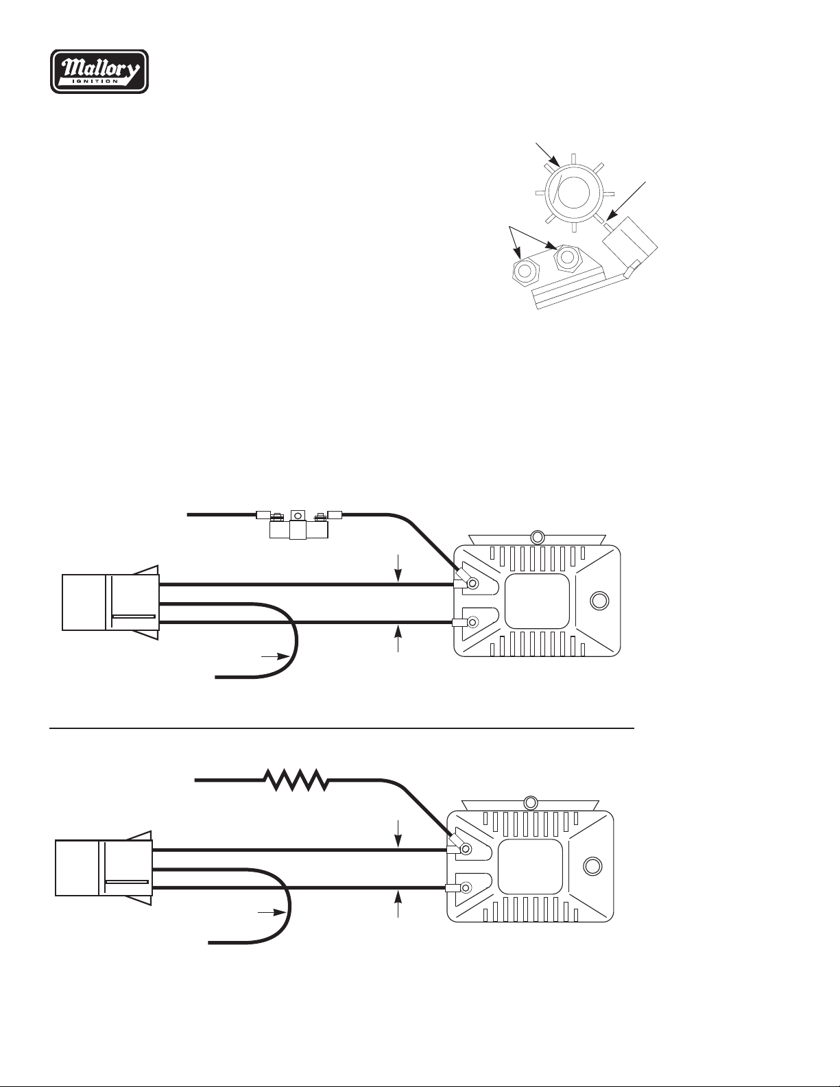
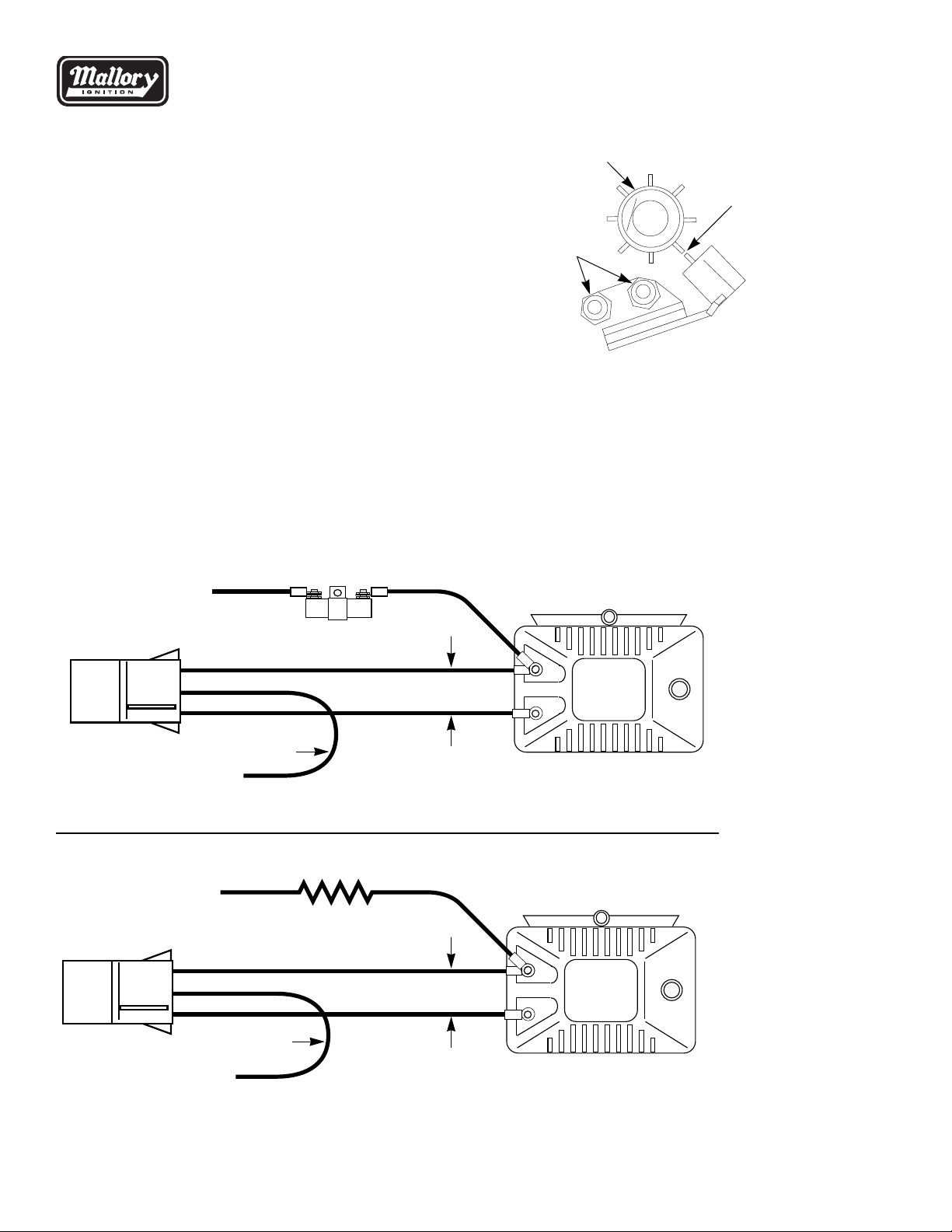
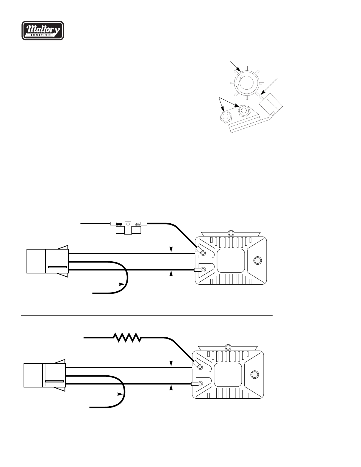
(2) Line up reluctor and pick-up as shown in Figure 1. If
battery voltage is present, take a flat blade screw driver
and short between the pick-up and reluctor blade
(Figure 2). The voltage should go up to 12 volts mo-
mentarily and then go back down to battery voltage. If
it does, then the module is good.
(3) If the test results are as follows:
(a) Voltage does not go up, module is bad and must
be replaced. May have been caused by power
surge, high resistance in the plugs or plug wires,
or improper ground. Possible charging system
load dump.
(b) Voltage always stays below 6 volts. Module has
been spiked by high voltage or amperage, lack of
ballast resistor, or improperly wired up. Possible
causes are:
(1) Faulty charging system (stuck or shorted
regulator/alternator)
(2) Faulty starting system (starter drag)
(3) Non suppression spark plug wires (copper or
stainless core wires). Need to be carbon core
or spiral wound plug wires.
(4) Large amperage alternator
(5) High amp stereo equipment
(6) CB Radio
(7) Direct shorts in the ignition or electrical
system
(8) Trying to start motor with a battery charger
hooked up
(9) Welding on the vehicle with the distributor
hooked up (disconnect 3-wire plug of the
distributor before welding)
(10) Faulty or improper grounding of module
If you must replace the module, use Part No. 609.
If you are not sure of the results after testing the module,
call Mallory Customer Service at (775) 882-6600.
Rev. Date: 07/ 6/02
FIGURE 2
FIGURE 1
Mallory-Ignition.com
5
This manual suits for next models
1
Table of contents
Languages:
Other Mallory Control Unit manuals