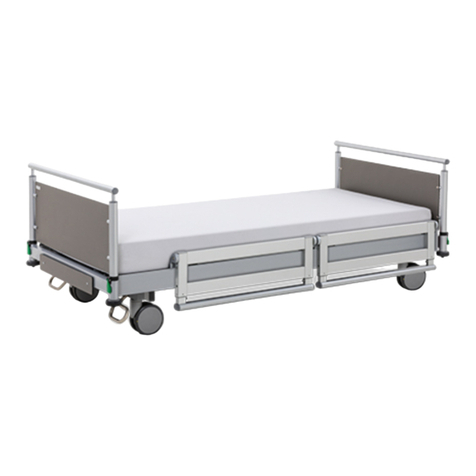
Malsch Impulse KL Series User manual

IMPULSE KL SERIES
INSTRUCTIONS FOR USE
CLINIC DESIGN

2 |

|3
Dear Customers,
By purchasing a clinical bed from Malsch care & clinic design®
you have obtained a long-lasting medical device with functions
that meet all the requirements of everyday care while maintain-
ing the highest standards of safety.
We would like to thank you for the trust you have placed in us.
Our company guarantees carefully selected materials and
continuous quality control while employing state-of-the-art
production technologies.
Complying with the usage and operating instructions helps to
prevent the risk of accidents and preserves the high value of
your clinical bed.

4 |
Specific function 7
Environmental Sustainability 7
Note regarding the
instructions for use 8
Pictograms / Symbols 8
Safety instructions 9
Technical Data 12
Rating Plate 13
Symbols on the patient’s hand controller 14
Symbols on the nurse’s control panel 15
Product designation 16
Functional representation 17
Description of function 18
Back rest 18
Mechanical release of the
Back rest (CPR) 18
Upper leg section 18
Height adjustment 18
Transfer position 19
Low position/
Fall prevention 19
Comfort sitting position 19
Auto contour 19
Trendelenburg-/
Anti-Trendelenburg position 20
Hand controller locking function 20
Braking and moving 21
Side rail (SR) adjustment 22
Integrated lying surface extension 23
Removable head / foot boards 24
Delivery and assembly 25
Accessories (optional) 26
Trapeze bar 26
Intravenous drip holder 26
CONTENTS

|5
Bed light 26
Hand controller holder 27
Horizontal hand controller 27
Mattresses 27
Side rail heightening 27
Urine bottle / bag / basket 28
5th wheel 28
Trouble shooting 30
Product safety 31
Cleaning and disinfection 32
Maintenance 33
Storage 33
Warranty and service 34
Declaration of conformity 34
Certificates 35

6 |
Room representation
Impulse 300 KL / Impulse 400 KL

|7
ENVIRONMENTAL
SUSTAINABILITY
Betten Malsch GmbH clinical beds are manufactured in ac-
cordance with the relevant regulations, and in line with state
of the art process technologies, and are free from hazardous
materials. The materials used to finish surfaces are CFC and
solvent free.
Clinical beds that are removed from circulation due to age or
irreparable damage must be disposed of in accordance with
disposal regulations.
Caution ! When disposing of metal, wood and
electrical waste, please observe the relevant
local regulations.
Betten Malsch GmbH clinical beds are used in hospitals and
care areas. These beds are designed exclusively for this pur-
pose. The comfort and functionality of the clinical beds make
life easier for staff as they carry out the tasks involved in pa-
tient care, and they aid compensation positioning and relief of
disabilities for treated patients in hospitals and care facilities.
If the clinical beds are used for other applications, then
prior written agreement from Betten Malsch GmbH is
required.
The product should be used as a working appliance and care
aid, and is subject to the insurance association’s regulations.
With regard to industry standards and regulations, the clinical
bed is a medical device. Therefore, this product should only be
used under medical supervision.
The clinical beds described in this instruction manual are
intended for adult patients with a body weight of at least
40 kg and a height of at least 146 cm. In accordance
with standard IEC 60601-2-52:2009/AMD1:2015, the
beds must not be used by patients whose body weight
and height do not meet these limits, or who have a BMI
under 17, as the risk of injury is significantly increased
for this group.
Caution! The use of incompatible side rails and
mattresses can lead to injury as body parts may
become trapped.
SPECIFIC FUNCTION

8 |
NOTE REGARDING THE
INSTRUCTIONS FOR USE
PICTOGRAMS / SYMBOLS
The following instructions and guidelines in this manual are for
the nursing staff or other persons and staff tasked with using
and working with the clinical bed.
The instruction manual must be available to
users at all times in order to avoid any errors
in operation and to guarantee fault free op-
eration. The nursing staff must have complete
knowledge of, and receive training on opera-
tion before using clinical beds for the first time.
The instruction manual is the basis for this.
The instruction manual is designed to apply to the Impulse KL
clinical bed range. The images, graphics and text it contains
may differ from the delivered equipment.
The manufacturer offers technician training for
maintenance and servicing work on their clin-
ical beds. A certificate obtained as part of this
training authorises the holder to carry out tech-
nical work independently on the beds.
To help easy orientation in this instruction manual, we some-
times use pictograms as follows:
Please note! Instructions labelled in this way must
be followed in order to avoid injury or damage!
Information! This pictogram identifies information
which relates to the current subject!
Observe the instructions for maintenance and
repair work! We can supply you with special ser-
vice instructions for accessories or complex main-
tenance instructions. You will find these at www.
bettenmalsch.de in the Service area.

|9
SAFETY INSTRUCTIONS
1. The instruction manual should be read and followed be-
fore using the clinical bed.
2. Explanation of the terms used on the rating plate.
CE: Conformity marking in accordance with Medical
Devices Directive
IPX6: Protection of electrical equipment from water spray
“only use in dry areas”
Protection Rating Class II (double insulation, pro-
tective insulation)
The instructions on the rating plate must be observed..
3. In the event of any fault or failing which could endanger
any person, the bed must not be used.
4. Only fully-trained specialists should operate electrically
operated clinical beds.
5. Before using the bed for the first time, the operator
should satisfy himself that it is safe to use and in a good
condition.
6. To ensure the patient does not fall when getting into or
out of the bed, the castors should always be placed in
the brake position.
7. The bed can be moved into various positions. When do-
ing so, you must take care to ensure no parts of the body
or other objects are located in the adjustment area.
8. Only nursing staff may adjust the side rails. Care should
be taken to ensure that the patient does not come into
contact with the side rails when adjusting the lying posi-
tion, to avoid trapping any part of the body.
9. The side rails must be taken down every day to check
their function, and should not bear any load of over 75
kg vertically or over 50 kg horizontally.
10. When using the mechanical emergency lowering of the
back rest (CPR), this must always also be held firmly to
avoid any sudden lowering.
11. The functions of the hand controller can be locked or
released via nurse’s control panel or by using the key
switch on the backside of the hand controller. The oper-
ation of the locking function should be checked on the
hand controller. Fp.14/p. 15
12. The power systems used must be operated using a VDE
approved power source – 220 V, 50/60 Hz mains socket.
13. The mains connection lead is also protected by a me-
chanical strain relief. Care must also be taken to ensure
that there are no sharp edges, mechanical stresses or
pinch/shear points.
14. The design of the hand controller means it can be hung
on the bed in such a way that the buttons are not activat-
ed inadvertently between 2 objects. Care must be taken
to ensure that the hand controller is fully accessible and
not trapped between the side rail and bedside table.
15. When using the clinical bed in a patient’s room, safety

10 |
distances between walls, window benches or other ob-
jects must be observed. Safety distances depend on the
design and model of the clinical bed and are based on
height adjustments and tilting motion. The minimum dis-
tance is 30 mm.
16. The following subjects and actions are considered to be
‘Improper Use’:
Unauthorised activation of the electrical functions
Use of the bed by children under 12 years old
Moving the bed by pulling the mains cable or side
rail
Simultaneous adjustment of the clinical bed by sev-
eral people
Activation of the functions by patients without prior
instruction
Pulling the mains cable to remove it from the elec-
tricity supply
Moving the bed on a sloping or insecure surface
It is important that the following safety instructions are ob-
served to prevent the risk of danger or injury to both patient
and carer and also avoid any potential damage to the bed:
The mattress used must fulfill the applicable safety
standards
For safety reasons, the handle on the trapeze bar
should be replaced completely every 5 years.
Service and repairs on electrical components
should only be carried out using original replace-
ment parts from the manufacturer and must be car-
ried out by specially trained staff.
The clinical bed is not suitable for extended oper-
ation beyond the working cycle of 2 minutes. If the
mains adapter is overloaded or if it overheats, it will
shut off automatically. Further operation will then
only be possible after a cooling period of approx.
30 minutes. (Observe the drive manufacturer’s
notes on the rating plate!)
Obstruction any part of the bed mechanism must
be absolutely avoided, as this can lead to damage
or complete disabling of the drive mechanism due
to overheating.
Equally, the safe working load should not be ex-
ceeded.
If an immobile patient remains in the same position
for a longer period without use of positioning aids,

|11
this can lead to pressure sores. The manufacturer
of the clinical bed is not liable for this in any way.
Electrically powered clinical beds are medical
products and are subject to technical safety checks
in accordance with the Medical Devices Directive
and Medical Devices Operator Ordinance § 6.
These regular checks must be carried out at least
once a year. A visual and operational inspection
of functional and electrical safety in accordance
with VDE0751 must be carried out to ensure this.
p. 33 Maintenance
Furthermore, electrically operated clinical beds
are electrical appliances, the safety of which is
the responsibility of the employer. The supervisory
function of this obligation is the responsibility of the
Berufsgenossenschaft für Gesundheitsdienst und
Wohlfahrtspflege (Employers’ Liability Insurance
Association for Health Service and Welfare Work
- BGW) and the Gewerbeaufsichtsamt (Trade Su-
pervisory Board). The regulations of the Employers’
Liability Insurance Association for Health Service
and Welfare Work apply (abbreviated to BGV, for-
merly VBG). In particular BGV A2 (formerly VBG)
“ Electrical Units and Equipment” applies, which
requires regular inspection of movable electrical
equipment with a guideline of 6 months but at least
once a year. These inspections may only be carried
out by an electrical specialist or someone with elec-
trical training using a special measurement and
inspection device. Inspections in accordance with
BGV A2 within the technical safety checks for med-
ical products may be carried out be specialist staff
trained by the manufacturer as these BGV inspec-
tions are included in the technical safety checks.
Electrically operated clinical beds are active medi-
cal products and must be listed in an inventory per
site in accordance with the Medizinprodukte Betrei-
berverordnung (MedProd-BetrV) Medical Products
Operation Regulations. We recommend you also
document the proper implementation of the re-
quired technical safety checks in this inventory and
note the date of the next inspection. The required
notes on technical safety checks already carried out
should be appended to the inventory.
Proper execution and traceable documentation of
the technical checks, maintenance and commis-
sioning work prescribed by the manufacturer, as
well as the technical safety checks are required in
order to preserve the warranty right of the purchas-
er. If the operator of a medical product does not
meet their obligations, then this may lead to a risk
of damage and accidents, for which the manufac-
turer is explicitly not liable.
Any maintenance work is to be carried out in ac-
cordance with VDE0751-1 and the subsequent
technical safety check is to be documented.

12 |
TECHNICAL DATA
Low voltage drive system
(SMPS switching power supply)
Electrical connection: 240V≈50Hz
Output voltage: 35V= 2A
Over-current off: 7,5-11,5A
Over-voltage off: 45V=
Standby operation: max. 0,5 Watt
Protection: IPX6
Protection class: II (with moveable earth conductor)
Dimensions:
Impulse 300 KL/400 KL 216 x 106 cm
Impulse XL KL 216 x 116 cm
incl. wall bumper
Lying surface (LF):
Impulse 300 KL/400 KL 200 x 90 cm
Impulse XL KL 200 x 100 cm
Height adjustment:
Impulse 400 KL approx. 27 bis 80 cm*
Impulse 300 KL/XL KL approx. 36 bis 86 cm*
Backrest adjustment: 71° reclining angle for backrest
12 cm mattress compensation
Upper leg adjustment: 43°
Trendelenburg: 14°
Antitrendelenburg: 15°
Maximum load: 250 kg
Impulse 300 KL / 400 KL ( 185 kg patient weight
+ 20 kg mattress
+ 45 kg accessories )
Maximum load: 300 kg
Impulse XL KL ( 235 kg patient weight
+ 20 kg mattress
+ 45 kg accessories )
Weight:
Impulse 300 KL/400KL approx. 120 kg
Impulse XL KL approx. 160 kg
* measured from the lying surface frame
Lifting system force:
Impulse 300 KL/400 KL 2x3000N
Impulse XL KL 2x6000N
LF adjustment force:
Impulse 300 KL/400 KL 2x3000N
Impulse XL KL: 3x3000N
Motor running time: 2min / off18min

|13
RATING PLATE
The rating plate is located on the underside of the lying sur-
face, at the head of the bed, on the right. To inspect the rating
plate, raise the head to the upper position.
1. Model id.
2. Serial number
3. Electrical voltage, frequency, power consumption
4. Operating time of the electrical adjustment: please ob-
serve this point to prevent over heating! For example, the
bed can only be continuously operated for max. 2 min.
within 18 min.
5. Protection of electrical equipment from water spray
“only use in dry areas” Protection Rating Class II
(double insulation, protective insulation)
6. Indicates the next technical check after delivery in ac-
cordance with VDE0751-1
Typical illustration of a rating plate on an Impulse 300 KL clinical bed, standard design with mains connection
7. Explanation of the terms used on the rating plate:
Application part type B
Directive 2002/96/EC relating to old electrical
and electronic equipment
Conformity marking in accordance with Medical
Devices Directive
Protection Rating Class II (double insulation,
protective insulation)
“Only use in dry areas”
“Follow the instructions”
2
1
3
4
5
6
7
Input: 230-240 V ≈50/60 Hz max 2A
Output: 35 V = 2 A
Operation: max. 2min / 18min off
Protection class: IPX6
250 kg
185 kg
BettenMalsch GmbH| Rohbergstraße9| D-36208Wildeck-Obersuhl
Tel.: +49 (0)6626 / 915 100 | Fax: +49 (0)6626 / 915 116
12
3
4
5
67
8
9
10
11 12
N
E
X
T
I
N
S
P
E
C
T
I
O
N
2016
Clinical bed Impulse KL
S/N 0815 1234567
8

14 |
SYMBOLS ON THE PATIENT’S HAND CONTROLLER
Blocking function
S1
Back rest
adjustment
up
S2
Back rest
adjustment
down
S3
Leg rest
adjustment
up
S5
Auto contour
up
S7
Lift adjustment
up
S9
Low
positioning1
S4
Leg rest
adjustment
down
R1
BLOCKED
No functions
operational
R2
FREE
All functions
available
R3
FREE
All functions
available
R4
FREE
All functions
available
S6
Auto contour
down
S8
Lift adjustment
down /
Transfer pos.1
S10
Comfort
seating
1only with Impulse 400 KL

|15
SYMBOLS ON THE NURSE’S CONTROL PANEL
ADJUSTMENTS
S1 CPR (electric)
S2 Shock position
S9 Back rest adjustment up
S10 Leg rest adjustment up
S11 Auto contour up
S12 Lift adjustment up
S13 Anti-Trendelenburg position
S15 Back rest adjustment down
S16 Leg rest adjustment down
S17 Auto contour down
S18 Lift adjustment down
S19 Trendelenburg position
BLOCKING FUNCTIONS
S3 Back rest adjustment block
S4 Leg rest adjustment block
S5 Auto contour block
S6 Lift adjustment block
S7 Trend /Anti-Trend block
S8 Locking of the hand controller (LED red = locked)
S14 Switch on the control panel (LED green = ON)
LED green = AC 220 Volt
Yellow LED indicates the battery is charging
S1 S2
S3
S9
S15
S4
S10
S16
S5
S11
S17
S6
S12
S18
S7 S8
S13 S14
S19
(LED red =
locked)

16 |
Impulse 300 KL (optional equipment)
Impulse XL KL
Impulse 400 KL
PRODUCT DESIGNATION

|17
Adjustable
back rest
Adjustable
upper leg rest
Seat section
(fixed)
5th wheel
(optional)
CPR
emergency
lowering
Trapeze bar mount on
the back of the frame
and inside on both
left/right
Bed panel
Nurse’s
control panel
Telescopic
bed linen storage
Adjustable
lower leg rest
Mount for IV holder
and accessories
Foot pedal with central
brake (6) and fixed
direction (5) of the
double castors
Bed fronts release
mechanism
Integrated bed extender
Adjustable
side rails
FUNCTIONAL REPRESENTATION
Telescopic
side rail extension

18 |
back rest drive is ready for use in every position after travelling
a short distance.
Upper leg section
Use the corresponding button on the hand controller to adjust
the upper leg section.
((Upper leg section operating button))
For safety reasons, this position should only be adjusted by
medical personnel.
The lower leg section can be put into a horizontal position by
nursing staff using a fine adjustment device. (stretched leg high
positioning)
Height adjustment
Use the corresponding button on the hand controller to adjust
the height.
(Height adjustment operating button)
Caution ! Please consider patient safety when
adjusting height! No other objects should be in
the area of the lifting mechanism.
DESCRIPTION OF FUNCTION
Depending on the design and type of clinical bed, the bed can
be put into the following positions by adjusting the back rest,
the upper leg and the lower leg sections as well as the height
of the bed:
Back rest
Use the corresponding button on the hand controller to adjust
the back rest.
(Back rest button)
The back rest has a range of movement equivalent to a length
compensation to the head section of the bed of 120 mm.
This function (mattress compensation) allows the patient to sit
in a comfortable position without compressing or restricting the
stomach or upper body.
Mechanical release of the
Back rest (CPR)
When using mechanical release of the back rest, hold it firmly
in the position engaged and take some weight off it if possible.
Then pull the release mechanism until the back rest goes down
noticeably. Slowly allow the back rest to fall back into its final
position.
Engaging the release mechanism:
Press the appropriate button (S2) on the hand controller; the

|19
Transfer position
(only with Impulse 400 KL)
The tranfer position allows an optimum positional mounting
and dismounting in the seat area of the bed at sitting height.
Use the corresponding button on the hand controller and hold
it until the position is reached.
(Transfer position operating button)
Low position/Fall prevention
(Only with Impulse 400 KL)
Use the corresponding button on the hand controller to adjust
the low position.
(Low position operating button)
By actuating the Button the bed moves out of the transfer posi-
tion to the low position.
Caution ! Before activating the button, you
must ensure that the lowered, splitted side rails
are retracted (Fp. 22, Fig. 1) and that there
is nothing under the bed!
Comfort sitting position
Use the corresponding button on the hand controller to set the
comfort sitting position.
(Comfort sitting position operating button)
When the button is activated the adjustment motors on the
lying surface and the lifting mechanism operate simultaneously
to bring the bed into a sitting position.
This function should only be used with mobile patients and
patients without any physical complaints.
Caution ! Please consider patient safety when
setting the comfort sitting position! No oth-
er objects should be in the area of the lifting
mechanism.
Auto contour
Use the corresponding button on the hand controller to set
auto contour.
(Auto contour operating button)

20 |
When this button is activated, the back and upper leg sections
are adjusted equally, so that the patient can be brought into an
upright sitting position.
This function should only be used with mobile patients and
patients without any physical complaints.
Caution ! Please consider patient safety when
setting auto contour! No other objects should
be in the area of the lifting mechanism.
Trendelenburg-/
Anti-Trendelenburg position
The Impulse clinical bed range comes with lying surface incli-
nation as standard.
The head or foot height is set using the button on the nurse’s
operating panel.
(Trendelenburg / Anti-Trendelenburg
operating button)
Caution ! Please consider patient safety when
adjusting bed inclination! No other objects
should be in the area of the lifting mechanism.
This function must only be used by specialist
staff and must be locked by specialist staff on
the back of the hand controller. Faulty settings
can lead to serious injury to the patient.
Hand controller locking function
The electrical unit combines state of the art technology and
first fault safety.
The locking function acts as one more safety precaution. The
locking function is located on the back of the hand controller
and is used by staff with a key switch. In the event of a failure
of the electrical motor, the functions can be disabled via the
corresponding rotary switch.
Operation:
The hand controller functions can be limited by turning the key
switch in the different switch positions. The symbols are clearly
described on p.14 of the instruction manual.
Operating the locking function is described in more detail on
p.14 (Hand controller symbols).
Further locking functions can be found on the nurse’s control
panel (FDiagram p.15)
This manual suits for next models
3
Table of contents
Other Malsch Medical Equipment manuals
Popular Medical Equipment manuals by other brands
EyeQue
EyeQue Personal Vision Tracker EQ101 product manual

Dürr Medical
Dürr Medical CR 35 VETwin Installation and operating instructions

Otto Bock
Otto Bock 50S5 MALLEO SENSA Instructions for use

bort medical
bort medical HerniaFix quick guide
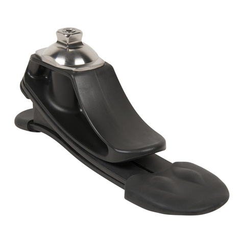
Fillauer
Fillauer K2 Foot product manual

Synthes
Synthes Air Power Line II Instructions for use

