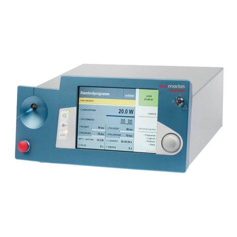
Service manual
diomax®MDL20
Revision 3 3
4.8.3 Removal/replace of the rotary knob center ........................................................32
4.8.4 Removal/replace of the rotary encoder light ring ................................................33
4.8.5 Removal/replace of the rotary switch ................................................................33
4.9 Removal/replace of the laser activating lamp incl. cable........................... 34
4.10 Removal/replace of the cable switch on system ...................................... 34
4.11 Removal/replace of the diode module including sensor board ................... 36
4.12 Removal/replacement of the cooling unit ............................................... 38
4.13 Removal/replace of the junction PCB ..................................................... 40
4.14 Removal/replace of the temperature switch/sensor ................................. 40
4.15 Removal/replace of the fan .................................................................. 41
4.16 Removal/replace of the power supply unit .............................................. 42
4.17 Removal/replace of the Loudspeaker ..................................................... 44
4.18 Removal/replace of the RS 232 and CAN connector with cable.................. 44
4.19 Removal/replace of the adapter board ................................................... 45
4.20 Removal/replace of the plug-in feet....................................................... 45
4.21 Adjusting the SMAX fibre connecting socket ........................................... 46
5Electrical measurements .............................................................48
5.1 diomax®electrical system .................................................................... 48
5.2 Service voltages ................................................................................. 49
5.2.1 +12V ............................................................................................................49
5.2.2 +5V..............................................................................................................50
5.2.3 +12V ............................................................................................................50
5.2.4 -12V .............................................................................................................51
5.3 Component power supply measurements ............................................... 51
5.3.1 Diode module ................................................................................................51
5.4 Testing high current safety shutdowns................................................... 52
5.4.1 Diode module shutdown when subject to current overflow...................................52
5.4.2 Pilot laser shutdown when subject to current overflow ........................................52
6Service Menu.............................................................................53
6.1 Device information ..............................................................................54
6.2 Incident log........................................................................................ 54
6.3 Adjust ...............................................................................................55
6.4 Calibrate............................................................................................ 56
6.5 Cooling ..............................................................................................57
6.6 Reset logfile ....................................................................................... 59
6.7 Reset all settings ................................................................................60
6.8 Activating the TESTIO-display............................................................... 60
7Flash updater by KLS Martin ........................................................61
8diomax®status codes .................................................................62
