Manaras Opera Rapido RSH Service manual
Addendum –
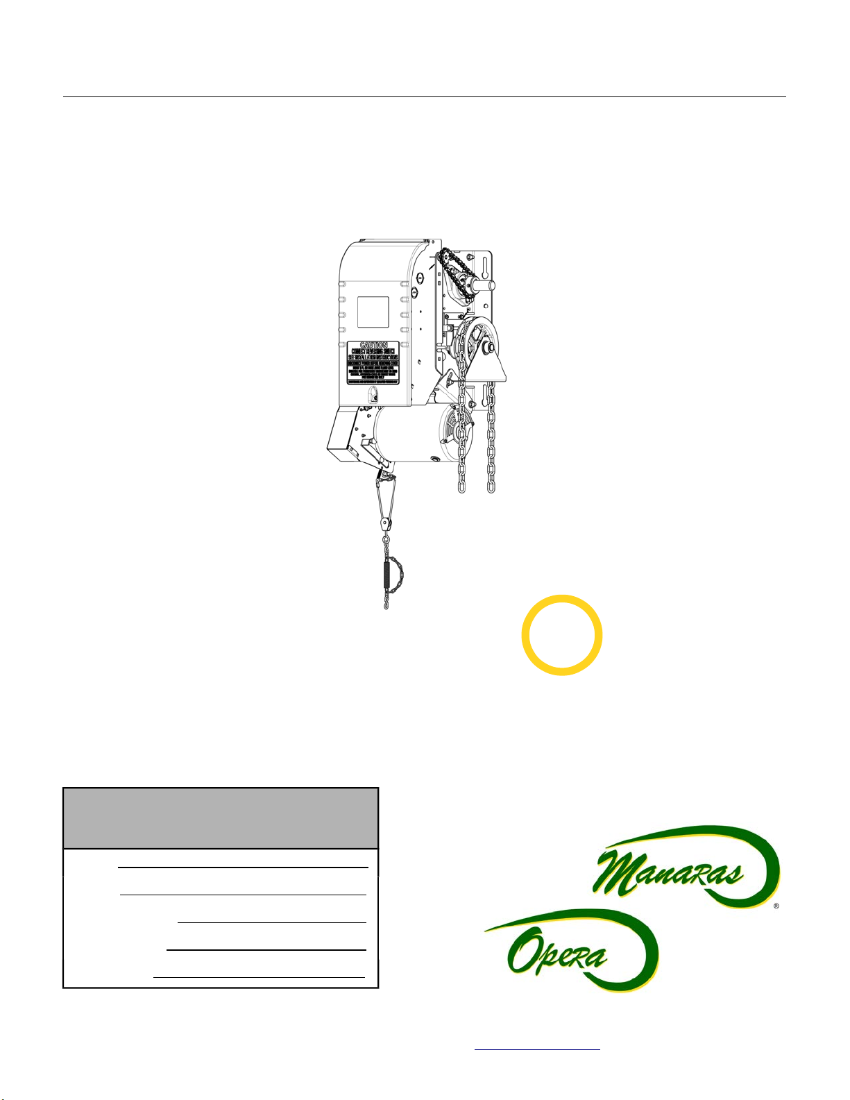
Addendum – Rapido
Rapido TM
High-Speed Operators
High-Speed Operators
This addendum is to be used in conjunction with the Installation & Instruction Manual.
Commercial & Industrial
Commercial & Industrial High-Speed
High-Speed Heavy- uty
Heavy- uty Operator
Operator
(For fast doors with high performance and speed managing requirements)
(For fast doors with high performance and speed managing requirements)
Rapido TM
RSH
RSH
READ AND FOLLOW ALL INSTRUCTIONS.
SAVE THESE INSTRUCTIONS.
GIVE TO END-USER.
Serial #
Model #
Wiring iagram #
Project #/Name
oor #/Name
For technical support, please call 1-800-361-2260 or visit www.manara .com for more information
FASTER
2X

2
TABLE OF CONTENTS
In tallation In truction ............................................................................................................................................... 3
1 General Specification and Dimen ion (RSH)..............................................................................................................................................4
2 Limit Switche & Limit Cam : Adju tment & Functionality..........................................................................................................................5
2.1 Limit Switch Adjustments: Open and Close Cam Settings.......................................................................................................................5
2.2 Limit Switch Functionality..........................................................................................................................................................................5
2.3 Limit Switch Adjustment Using Manual Hand Chain.................................................................................................................................6
2.4 Low Voltage (Controls) and High Voltage (Power) Connections..............................................................................................................7
2.5 Main Power Supply Connection................................................................................................................................................................7
3 Electrical Drawing ............................................................................................................................................................................................8
3.1 1 Phase 120VAC Rapido Operator and BOAR 070...............................................................................................................................8
3.2 1 Phase 240VAC Rapido Operators and BOAR 070.............................................................................................................................9
Warranty...................................................................................................................................................................... 10
Note ............................................................................................................................................................................ 11
For technical support, please call 1-800-361-2260 or visit www.manara .com for more information

3
Installation Instructions
IMPORTANT INSTALLATION INSTRUCTIONS
WARNING
TO RE UCE THE RISK OF SEVERE INJURY OR
EATH TO PERSONS:
1. REA AN FOLLOW ALL INSTALLATION INSTRUCTIONS.
2. Install only on a properly operating and balanced door. A door that is operating
improperly could cause severe injury. Have qualified service personnel make repairs
to cables, spring assemblies and other hardware before installing the operator.
3. Remove all pull ropes and remove, or make inoperative, all locks (unless
mechanically and/or electrically interlocked to the power unit) that are connected to
the door before installing the operator.
4. Installation of this door operator must be done by a qualified installer.
5. Verify that the operator is correct for type, size of door and frequency of use per the
operator specifications.
6. Install the door operator at least 8 feet (2,44 m) or more above the floor if the operator
has exposed moving parts. Covers or guarding, provided by the manufacturer, must
be installed when the operator is mounted less than 8 feet (2,44 m) above the floor.
7. o not connect the door operator to the source of power until instructed to do so.
8. Locate the control station: (a) within sight of the door, (b) at a minimum height of
5 feet (1,5 m) above floors, landings, steps or any other adjacent walking surface so
small children cannot reach it, and (c) away from all moving parts of the door.
9. Install the Entrapment Warning Placard next to the control station in a prominent
location.
10. For products having a manual release, instruct the end user on the operation of the
manual release.
11. If you have any questions about the safety of the door operating system, do not install
the operator, contact Manaras-Opera at 1-800-361-2260.
For technical support, please call 1-800-361-2260 or visit www.manara .com for more information
4
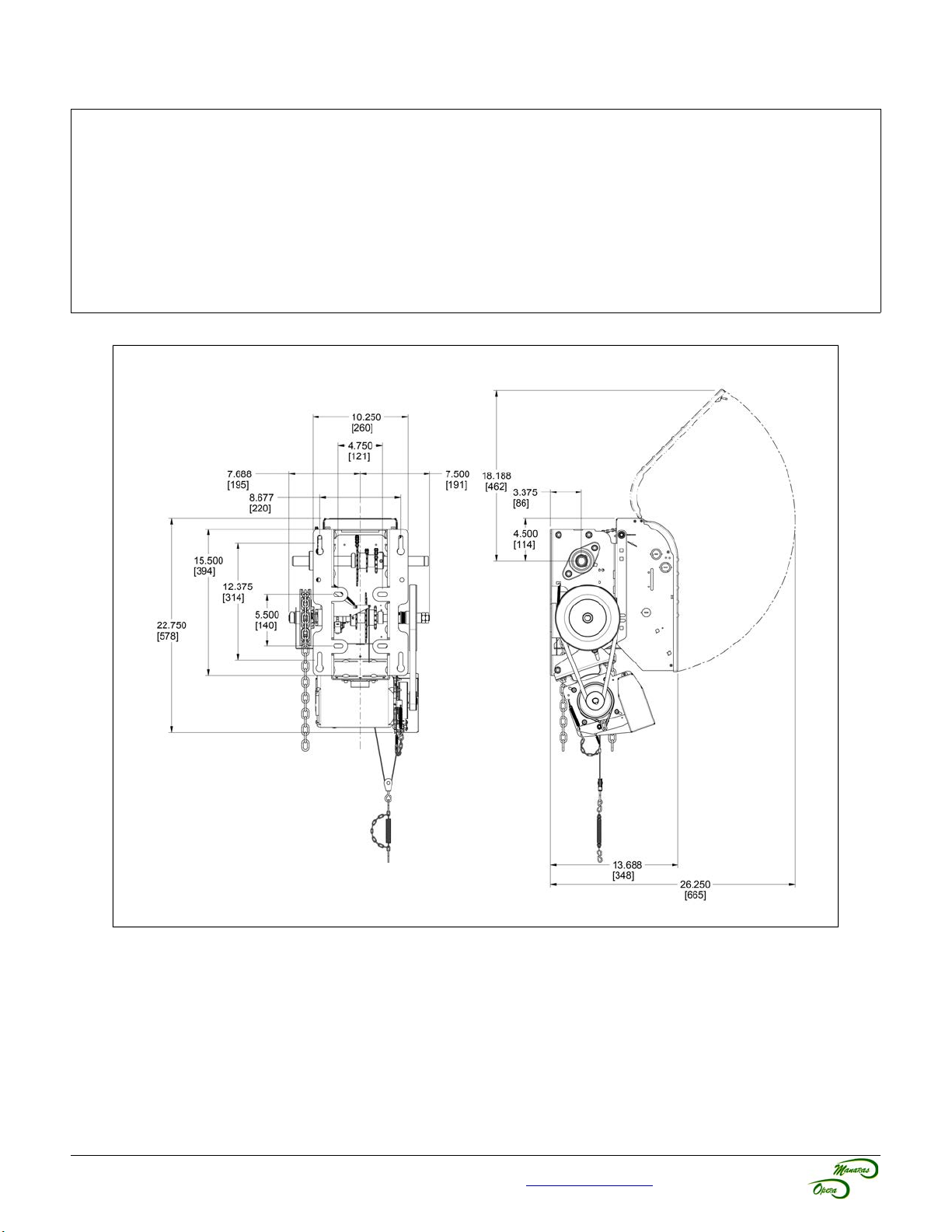
1 General Specifications and Dimensions (RSH)
SUPPLY VOLTAGE............................................115 VAC single-phase
CONTROL VOLTAGE.........................................24 VAC class 2 transformer, 2 amp fuse type ACG
MOTOR..............................................................Continuous duty, 1 horsepower
MOTOR VOLTAGE.............................................208 VAC three-phase
OPERATOR OUTPUT SPEE ...........................88 RPM
NET WEIGHT (Operator only)............................96 Lbs (44 Kg)
STAN AR WIRING TYPE...............................C2 (momentary contact to open/stop and constant-pressure-to-close)
APPLICATION....................................................Ultra high-end heavy duty v-belt drive for sectional doors
UTY.................................................................>100 cycles/day
Maximum Door Size: To be evaluated based on the door speed required.
For technical support, please call 1-800-361-2260 or visit www.manara .com for more information
Figure 1 - RSH (RapidoTM) Dimensions

5
2 Limit Switches & Limit Cams Adjustment & Functionality
WARNING
To reduce risk of SEVERE INJURY or EATH to persons:
•o not attempt to make limit switch adjustments unless power has been electrically disconnected.
•The adjustment of the deceleration limit may affect the door's stop position.
2.1 Limit Switch Adjustments Open and Close Cam Settings
This operator is equipped with the ACCU-CAM® feature, for precise and quick one-handed limit setting adjustments.
To adjust the limit cams, see Figure 2.
1. Pull the cam's retaining bracket back.
2. Turn the cams for limit adjustment: turning cams toward the center of the limit shaft increases door travel or
turning the cams toward the limit switch decreases door travel.
2.2 Limit Switch Functionality
Open Limit Switch
When activated, the Open Limit Switch will stop the operator while the door is travelling in the upward direction.
Should be adjusted accordingly to stop door in fully open position.
Close Limit Switch and Advanced Close Limit Switch
Close Limits are not present on operators with an ECB. In it's place, the microprocessor has a built-in patented
Advanced Close Time feature. While the door is travelling downwards and once the Advanced Close Limit Switch is
activated, the door will stop after 200 milli econd . The distance travelled varies according to the speed of the door.
The value is fixed and cannot be re-programmed or adjusted.
Deceleration Limit Switch
The operator is provided with a Variable Frequency Drive. The deceleration time is factory set, however it can be
adjusted on-site using the eceleration Limit Switches (Open and Close).
For technical support, please call 1-800-361-2260 or visit www.manara .com for more information
Figure 2 - Limit Switches and Cams djustment
Advanced Close
Limit Switch
eceleration
Open Limit Switch
Open Limit
Switch eceleration
Close Limit Switch
Increa e
Door Travel
Open Cam Close Cam
Cam Retaining
Bracket
Decrea e
Door Travel
Open Side Close Side
Increa e
Door Travel

6
2.3 Limit Switch Adjustment Using Manual Hand Chain
Table 1 - Limit Switch djustment Procedures
Limit Switch Adju tment Procedure
Open Limit
1. Using the hoist, manually raise the door to a nearly opened position or desired open
position.
2. Pull the cam-retaining bracket from the Open side, see Figure 2, and rotate the Open cam
manually until it activates the Open Limit Switch sufficiently so that a “click” can be heard.
3. Release the cam-retaining bracket and make sure that the bracket engage in the slots
of both cams.
Advanced
Clo e Limit
1. U ing the hoi t, manually lower the door to approx. 6” above the ground.
2. Pull the cam-retaining bracket from the Close side, see Figure 2, and rotate Close cam
manually until it activates the Close limit switch sufficiently so that a “click” can be heard.
3. Release the cam-retaining bracket and make sure that the bracket engage in the slots
of both cams.
Limit Switch
Fine
Adju tment
1. Limit switch fine adjustment SHOUL be done after the main power supply is connected
to the operator.
Note: One (1) notch on cam is equal (=) to about ½” of the door travel.
For technical support, please call 1-800-361-2260 or visit www.manara .com for more information

7
NOTICE
•The installer MUST test for proper connection and functionality of the operator and its accessories
before leaving the job site.
•The installer should also perform a demonstration for the end-user.
2.4 Low Voltage (Controls) and High Voltage (Power) Connections
1. Route the main power line wires either
from the right or from the left of the
control panel, as shown in Figure 3.
2. Route all low voltage control wires, as
shown in Figure 3. KEEP LOW
VOLTAGE WIRES SEPARATE FROM
LINE VOLTAGE WIRES.
3. USE COPPER CON UCTORS ONLY.
2.5 Main Power Supply Connection
Single-Pha e (115 VAC)
Correct motor rotation: Switch ANY TWO lines from the
electrical motor (M1 / M2 / M3) on the drive.
For technical support, please call 1-800-361-2260 or visit www.manara .com for more information
Figure 3 - Low Voltage (Controls) and
High Voltage (Power) Connections
Control
Ground Lug
Power Terminal
Block
NEUTRAL
LIVE
Power
Control
Power


10
Warranty
Manaras-Opera warrants its operators to be free from defects in material and workmanship under normal and proper
use for a period of two years from date of invoice, unless otherwise stated. Mechanical, electrical and electronic
accessories are warranted for one year from date of invoice, unless otherwise stated. Wearing parts such as clutch
pads, v-belts, and brake bands are excluded from warranty.
Manaras-Opera’s only obligation shall be to repair or replace defective equipment which does not conform to the
warranty. Manaras-Opera shall not be liable for any injury, loss or damage, direct or consequential, arising out of the
inability to use the equipment. Before using, Buyer and/or the ultimate User shall determine the suitability of the
product for its intended use, and User assumes all risks and liability in connection therewith. The foregoing may not
be changed except by an Agreement signed by an authorized representative of Manaras-Opera.
The articles that are replaced pursuant to the terms of this warranty shall be retained by Manaras-Opera, and the
User is responsible for any freight costs relating to repair or replacement.
The foregoing warranty is exclusive and in lieu of all other warranties of quality, whether written, oral or implied
(including any other warranty of merchantability or fitness for purpose).
The following are exclusions from warranty:
• If usage, product modification, adaptation or installation are not in accordance with our installation and
operating instructions.
• If the product has been opened, dismantled or returned with clear evidence of abuse or other damage.
• If our written specifications are not properly applied by the Buyer when selecting the equipment.
• If our written instructions for installation and wiring of the electrical connections have not been followed.
• If our equipment has been used to perform functions other than the functions it was designed to handle.
• If Manaras-Opera equipment is used with electrical accessories (switches, relays, etc.) that have not been
previously approved in writing by the Manaras-Opera Engineering epartment.
• If electrical accessories and other components have been used in disregard of the basic wiring diagram for
which they were designed.
All costs related to installation and re-installation of the Manaras-Opera equipment covered by this warranty are not
the responsibility of Manaras-Opera. Manaras-Opera will not be responsible for any consequential damages following
installation procedures performed by the Buyer or the User. If the Buyer resells any Manaras-Opera products to
another Buyer or User, it shall include all of the terms and provisions of this warranty in such resale. Manaras-Opera’s
responsibility to any such Third Party shall be no greater than Manaras-Opera’s responsibility under the warranty to
the original Buyer.
Return
No returns will be accepted without prior written authorization by Manaras-Opera. All returns must be accompanied by
a Return Authorization Number issued by Manaras-Opera, and all unauthorized returns will be refused. The return
shipment is to be freight prepaid by the Buyer, and under no circumstances shall the Buyer deduct the value of the
returned merchandise from any remittance due. A restocking fee of 15% of the Manaras-Opera sale price will be
charged for all returns not covered under warranty.
For technical support, please call 1-800-361-2260 or visit www.manara .com for more information

Reg. T.M. of 9141-0720 Québec Inc.
ADD1011 REV 8 – 2016/08/26
Table of contents
Popular Industrial Equipment manuals by other brands


Flex-A-Seal
Flex-A-Seal 23M Installation, operation, maintenance guide

Carbatec
Carbatec TH-B317P owner's manual

Oriental motor
Oriental motor EZ limo EDR36D-K operating manual

FEB
FEB 850 Series installation instructions

Delta
Delta HEX080QA Series instruction manual

Thomas&Betts
Thomas&Betts Elastimold 274FT operating instructions