Cold Jet PR120H User manual

PR120H Pelletizer
USER
MANUAL
Original Instructions [English] 09-11-22 REV 5

PR120H
User’s manual
Version: 5
Page: 1 of 26
ate: 09.11.2022
Copyright © 2022 Cold Jet, K
ALL RIGHTS RESERVE . PRINTE IN ENMARK.
UE TO CONTINUE PRO UCT EVELOPMENT THIS INFORMATION MAY CHANGE WITHOUT NOTICE. THE
INFORMATION AN INTELLECTUAL PROPERTY CONTAINE HEREIN IS CONFI ENTIAL BETWEEN COL JET AN THE
CLIENT AN REMAINS THE EXCLUSIVE PROPERTY OF COL JET. IF YOU FIN ANY PROBLEMS IN THE OCUMENTATION,
PLEASE REPORT THEM TO US IN WRITING. COL JET OES NOT WARRANT THAT THIS OCUMENT IS ERROR-FREE.
NO PART OF THIS PUBLICATION MAY BE REPRO UCE , STORE IN A RETRIEVAL SYSTEM, OR TRANSMITTE IN ANY
FORM OR BY ANY MEANS, ELECTRONIC, MECHANICAL, PHOTOCOPYING, RECOR ING OR OTHERWISE WITHOUT THE
PRIOR WRITTEN PERMISSION OF COL JET.
THIS MANUAL REFLECTS THE PRO UCT CONFIGURATION AS WAS CURRENT AT THE TIME OF ITS WRITING. AN ITEM’S
ISPLAY IN THIS MANUAL OES NOT GUARANTEE THE ITEM’S AVAILABILITY AT ANY TIME IN THE FUTURE. IMAGES
SHOWN ARE FOR REPRESENTATION PURPOSES ONLY. PRO UCTS MAY VARY FROM THE IMAGES ISPLAYE . COL JET
IS NOT LIABLE FOR TYPOGRAPHICAL ERRORS OR CHANGES TO SPECIFICATIONS PRESENTE .

PR120H
User’s manual
Version: 5
Page: 2 of 26
ate: 09.11.2022
T
ABLE OF
C
ONTENTS
Introduction 4
About the PR120H 4
System escription 6
Functional description 6
System Identification 7
Supplier Responsible for the Equipment 7
TECHNICAL ATA - SAFETY REGULATIONS 8
TECHNICAL FACTS OF FROZEN CO2 9
SAFETY REGULATIONS 10
General Measures 10
Personnel Qualifications 10
Security and Risk 10
SAFETY OPERATION 14
Emergency Stop 14
Machine Safety 14
Liquid CO2 Leakage 14
Stop Production 14
aily checkup before start-up 14
MACHINE STRUCTURE 15
MACHINE OPERATION START-UP 16
MACHINE CONTROLS 17
REPAIR AN WARRANTY 20
Repair 20
MAINTENANCE 20
egassing system 20
Hydraulic station 20
Terms of Warranty 21
Cleaning the PR120H 21
INSTRUCTION – UNPACKING AN PREPARATIONS BEFORE INSTALLATION 22
End of life for the PR120H 24
Notes 25
Contact Information 26

PR120H
User’s manual
Version: 5
Page: 3 of 26
ate: 09.11.2022

PR120H
User’s manual
Version: 5
Page: 4 of 26
ate: 09.11.2022
INTRODUCTION
This manual should be kept with the machine and be readily accessible to machine users. This manual contains information
on the safety and operation. The graphics used in this manual may show machine details that may be different than the
actual machine. Components of the machine may have been removed for illustrative purposes or the continuing
improvement of the machine’s design may cause changes that are not included in this publication.
The owner of this machine is responsible for verifying the operator of this machine is properly trained and understands
the contents of this manual
Abou he PR120H
The Cold Jet PR120H presents a state-of-the-art dry ice pelletizer packed with features for easy operation, swift production
shifts and high capacity.
The Cold Jet PR120H has a quick start-up that reduces downtime and loss of valuable CO2. This is secured by a start-up
sequence purging the liquid line and using a special valve to fill the chamber.
The Cold Jet PR120H uses a heat exchanger for sub-cooling the liquid CO2, enabling a higher utilization of the liquid CO2
and a better liquid to solid CO₂ ratio.
The machine parts are protected by a moisture-free enclosure, which also reduces the noise level to a minimum - below
75 dB(a). The Cold Jet PR120H provides a non-stop supply of high-density dry ice pellets. The source of raw material to
produce pellets is liquid carbon dioxide conserved at low temperatures in a storage tank.
The control system of the Cold Jet PR120H, based on Beckhoff Industrial PC and HMI system, offers maximum functionality
and a user-friendly interface. Production is started by pressing one button. Just-In-Time production minimizes labour and
waste during production.

PR120H
User’s manual
Version: 5
Page: 5 of 26
ate: 09.11.2022

PR120H
User’s manual
Version: 5
Page: 6 of 26
ate: 09.11.2022
SYSTEM DESCRIPTION
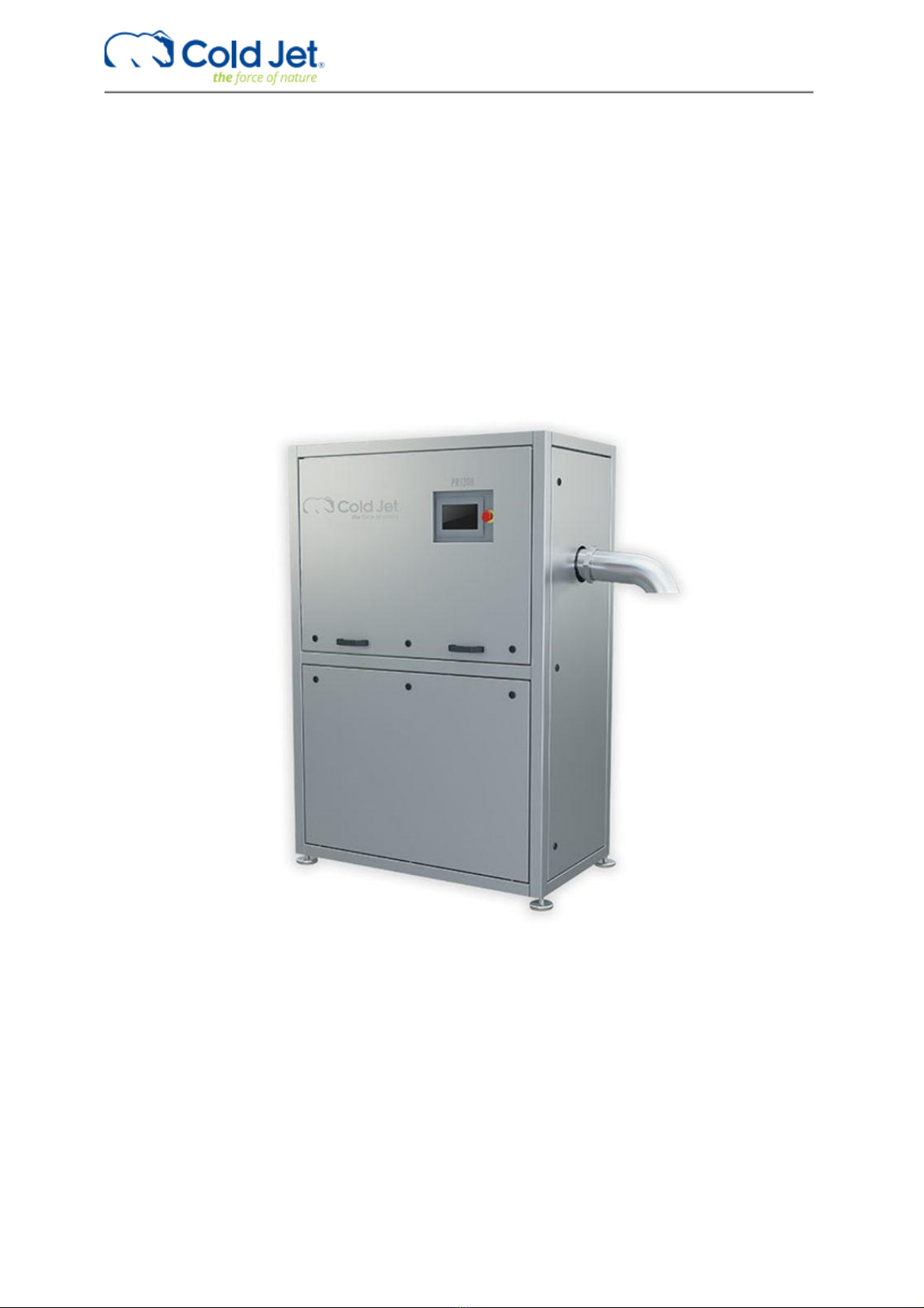
This user’s manual covers the Cold Jet PR120H. The main parts are described in the machine structure section. Operating
instructions for add-ons can be found in separate instructions, and are not included in this manual.
Func ional descrip ion
The main function of the Cold Jet PR120H is to produce dry ice pellets from liquid carbon dioxide.
This is performed by a sequence of operations executed by the Beckhoff Panel PC. The main steps in a normal production
are as follows and refer to PI diagram P294-1-11991-B for Cold Jet PR120H CE and P294-1-16309-A for Cold Jet PR120H
UL:
1. Start up
2. Production
3. Standby
4. Shut down
At every start-up, the hydraulic cylinder =G01-G1-MO1 for extruder piston is extracted to its maximum position to extrude
the CO2 snow in the chamber in case of emergency stop or machine error.
Liquid CO2 is fed from an external CO2 tank (not part of this description – see supplier information) through an insulated
pipe to the Cold Jet PR120H. It is recommended to use a gas separator to eliminate gaseous CO2 from the liquid CO2.
When the hydraulic cylinder =G01-G1-MO1 for the extruder piston is retracted CO2 in valve =W01-Q1 and injection valve
=G01-Q2 will open and purge gaseous CO2 through the chamber, degassing filters and via degassing pipes to CO2 out.
When temperature =W01-TT1 in the liquid CO2 is -14°C, first injection will begin using =G01-Q1 and proceed until the
timer is reached. The degassing valve =G01-Q5 on the extruder chamber will open to reduce chamber pressure before
the hydraulic cylinder =G01-G1-MO1 for the extruder piston will extract until pressure set point is reached and the hydraulic
cylinder will again retract. This will continue until plug thickness set point is reached. When plug thickness is reached,
production will commence.
In production mode CO2 In valve =W01-Q1 and the Injection valve =G01-Q1 will open until the timer is reached. The
degassing valve =G01-Q5 on the extruder chamber will open to reduce chamber pressure before hydraulic cylinder =G01-
G1-MO1 for the extruder piston will extract until plug set point is reached and the hydraulic cylinder will again retract. This
cycle will continue until a different step is selected. uring production, it is possible to set Cold Jet PR120H in standby.
When maximum standby time is reached, the Cold Jet PR120H will run a shutdown sequence.
The shutdown sequence ensures that the Cold Jet PR120H is stopped in a proper
position to empty extruder chamber from dry ice snow and avoid moisture in the
extruder chamber. The hydraulic cylinder =G01-G1-MO1 for extruder piston will
extract to maximum position and return to shutdown set point position.
The PR120H is supplied with a cap to be installed on the outlet sprout at production
stop. This will hinder dew from condensating inside the extruder cylinder and filter.
If the cap is not installed at production stops, it can cause damage to vital
components inside the extruder unit. Before production start-up, the cap should be
removed.

PR120H
User’s manual
Version: 5
Page: 7 of 26
ate: 09.11.2022
Sys em Iden ifica ion
The machine is double marked with EU and UL approval.
Example of a system identification, values and numbers may vary
Supplier Responsible for he Equipmen
Cold Jet ApS
Industrivej 68
K-6740 Bramming
enmark
Phone: +45 75 56 15 00
Homepage: www.coldjet.com

PR120H
User’s manual
Version: 5
Page: 8 of 26
ate: 09.11.2022
TECHNICAL DATA - SAFETY REGULATIONS
Ra ed Ou pu :
Kg/h: up to 120 / lbs/h: up to 265
Of high quality dry ice pellets, depending on the extruder plate applied
Pelle Size:
iameter:
Mm: 3 - 10 or 16 / Inch: 1/8 – 3/8 or 5/8
Cylindrical - length varying from:
Mm: 50 to 100 / inch: 2 to 4
Inle Liquid CO2 Pressure:
Bar: 16 – 22 / Psi: 232 – 319
Liquid CO2 Dryness Frac ion:
The water content should not exceed 35 ppm and should not be less than 5 ppm – or equivalent to a dewpoint
Temperature of -66°C to -51°C (-86.8°F to -59.8°F).
NOTE:
The liquid CO2 supply must be completely free of oil and must have a purity of minimum 99.9%.
Liquid CO2 Supply Pip :
Internal dia. 20 mm (3/4 inch), very well insulated with a minimum number of bends and fittings.
NOTE: If over 20 m (65.6 feet) in length, always use an internal dia. of 25 mm (1 inch).
Compr ss d air / CO2 gas pr ssur :
Bar: 8 – 10 / psi: 116 – 145
Air quality Class 3 – according to ISO 8573-1
Pow r Supply:
3 x 400 V AC + PE, 50Hz,
TN-S Earthing system
Imax. 16 A
480V AC Solidly Grounded Wye Source
3 Phase + GN wire, 60Hz
Imax. 16 A
Control Panel SCCR: 25kA rms symmetrical 480VAC Max.
Rat d pow r:
8,3 kW / 10,7 Hp
Machin Dim nsions:
Length: 1150 mm / 45,3 in
Width: 650 mm / 25,6 in
Height: 1738 mm / 68,4 in
Weight: 754 kg / 1662 lbs
Nois l v l: b low 75 dB(a)

PR120H
User’s manual
Version: 5
Page: 9 of 26
ate: 09.11.2022
TECHNICAL FACTS OF FROZEN CO2
ry ice is frozen carbon dioxide (CO
2
). It is much denser and colder than traditional ice. ry ice is -79°C (-109.3°F).
Traditional ice is 0°C (32°F).
In addition, dry ice does not melt - it sublimates. Sublimation is the process of going directly from solid form into gas form.
ry ice by-passes the liquid form, hence the “dry” ice.
The first step in producing dry ice is to turn the carbon dioxide gas into a liquid. This is done by compressing the CO
2
and
removing excess heat. Next, the pressure is reduced over the liquid carbon dioxide by sending it through a snow valve
(expansion valve). As the liquid evaporates, it absorbs heat, causing some of the CO
2
to freeze into dry ice snowflakes.
The dry ice snow is then exposed to compaction by a large press to form blocks. ry ice is much heavier than traditional
ice, weighing 1.7 times as much. CO
2
is a natural substance produced by the combustion of organic compounds, and is
exhaled by humans and other living beings.
Pressure- Temperature phase diagram for CO
2
CO
2
is:
:: Non-toxic
:: Transparent
:: Odourless gas under atmospheric pressure and temperature
:: 1½ times heavier than air
:: The atmosphere consists of 0.03% CO
2
CO
2
exis s in hree forms:
:: Gas, e.g. used in the food industry
:: Liquid, kept under pressure
:: Solid, dry ice

PR120H
User’s manual
Version: 5
Page: 10 of 26
ate: 09.11.2022
SAFETY REGULATIONS
G n ral M asur s
The Cold Jet PR120H manual contains instructions on starting up, operating and servicing the machine. The operator must
follow the instructions in the manual. Moreover it is important that the owner makes sure that the operator understands
the contents of this manual and follows its guidelines and safety regulations.
P rsonn l Qualifications
Employees, who are in charge of mounting, operation, service and maintenance must be adequately qualified to take care
of such job functions.
If the employees do not possess sufficient knowledge, they must be instructed and trained properly. If necessary, this can
be arranged in cooperation with the manufacturer of the machine.
The owner of the machine shall make sure that the operator, who is to work with the Cold Jet PR120H, fully understands
the importance of studying the content of the manual and complying with the SAFETY REGULATIONS described on the
following pages as well as those placed on the machine.
S curity and Risk
The Cold Jet PR120H is designed so as to comply with the EC eclaration of Conformity for Machinery. Therefore, using
the machine does not pose a risk to the operator when the instructions in this manual are followed carefully.
It is important that the operator carefully follows the safety signs on the machine and the safety regulations described
later in this manual and that the operator reads and understands the content of this manual before starting up the machine.
Installation must be carried out according to the instruction ”Unpacking and preparations before installation”.
The machine may only be installed by authorized personnel, that is electricians with knowledge of the Council irectives
73/23/EEC and the 89/336/EEC and the 89/336/EEC (or similar directives in other parts of the world).

PR120H
User’s manual
Version: 5
Page: 11 of 26
ate: 09.11.2022
Safe y Labels
The symbols used on the machine were developed by the International Organization for Standardization (ISO) and are
defined below. These symbols may include yellow warnings triangles, blue mandatory action circles, or red prohibited
action circles.
Danger of Suffoca ion
ry ice pellets are CO
2
in solid form. At ordinary atmospheric pressure, CO
2
can only exist in this solid form at temperatures
of -79°C (-110°F) or lower. Therefore, during dry ice production, the CO
2
will immediately be heated and thus transform
from solid form into gas form.
Please note:
Since the specific gravity of CO
2
is higher than that of ordinary atmospheric air, the air with its contents of oxygen will be
replaced by CO
2
if the dry ice production is taking place in small or insufficiently ventilated rooms.
Therefore, please note the following:
1. Low CO
2
concentrations (3-5%) cause headaches and fast breathing.
2. CO
2
concentrations of (7-10%) cause headaches and nausea and may result in unconsciousness.
3. Higher CO
2
concentrations result in unconsciousness and at worst it may cause suffocation.
High CO
2
concentrations may result in unconsciousness due to displacement of oxygen. Therefore, always make sure to
provide sufficient ventilation of the working area, and always avoid producing dry ice in small rooms.

PR120H
User’s manual
Version: 5
Page: 12 of 26
ate: 09.11.2022
S a ic Elec rici y
ry ice can cause electrostatic discharges. However, the equipment bonded to ground to minimize electrostatic discharge,
and the warning sign is only meant to instruct the operator to avoid placing the equipment in rooms containing explosive
gasses.
Also, it is recommended to use a plastic shovel in the dry ice container.
Danger of Congela ion
CO
2
in solid form has a temperature of -79°C /-110°F or lower at atmospheric pressure and can therefore cause serious
congelation injuries.
IMPORTANT!
The dry ice is extremely cold; therefore, do not touch parts of the machine which are in direct contact with the dry ice
without wearing appropriate protective clothing and gloves.
Pinch Poin Hazard
If the plexiglass covers in front of the extruder plates are removed, the operator will be exposed to pinch point hazards.

PR120H
User’s manual
Version: 5
Page: 13 of 26
ate: 09.11.2022
Wear Pro ec ive Gloves
uring work with the conveyor system, the operator must wear protective gloves in order to avoid contact with the dry
ice or with parts of the machine which are in direct contact with the dry ice.
How o Lif / Transpor
1. The PR120H is supplied with thread holes for lifting eyes. Always use lifting eyes to lift the PR120H.
2. Always lift the Pelletizer according to the lifting Instruction in this manual.
3. Lifting over persons and animals is prohibited.
4. Always use a forklift truck to transport the Pelletizer.
5. Pick up the Pelletizer from the side as shown in the drawings.
6. Transport the Pelletizer upright.
7. Make sure that the forks are sufficiently long to fully engage the Pelletizer.
8. Always check that the forks are adjusted to maximum width.

PR120H
User’s manual
Version: 5
Page: 14 of 26
ate: 09.11.2022
SAFETY OPERATION
Emergency S op
All equipment is connected to the general emergency system for the Cold Jet PR120H.
When an emergency-stop device is activated, all components located in the emergency zone will be disconnected from
their power source.
Machine Safe y
There are machine safety measures in the following areas:
Extruder unit
Extruder plate changer
In these areas, protective covers are in place.
The covers are provided with locking screws to deter removal.
Required performance level PLr = c Implemented in category = Cat3.
There is a danger of congelation/frost bite by touching machine parts cooled down by dry ice.
To prevent congelation the entire machine enclosure is provided with locks that require special tools to open.
Liquid CO2 Leakage
If liquid CO
2
is leaking from any point of the CO
2
pipe system, the CO
2
supply must be stopped immediately. Localize the
leakage and repair.
S op Produc ion
1. The machine is stopped by pressing the “Start / Stop” button.
NOTE: This will activate the shutdown procedure.
2. The CO
2
valve on the machine inlet will automatically close. It is recommended to close the manual valve on the
mounting kit before leaving the machine unused for a longer period of time.
3. Cut off the main electric supply.
NOTE:
o not shut off the main switch on the cabinet inside the machine before the inlet CO
2
pressure is ZERO. The CO
2
pressure can be checked on the “Process values” page.
Daily checkup before s ar -up
1. Check the oil level in the sight glass.
2. Check the pipe system for leaks.
3. Check the operation time since service intervals.

PR120H
User’s manual
Version: 5
Page: 15 of 26
ate: 09.11.2022
MACHINE STRUCTURE
PR120H
1 Pelle s ou le sprou
2 Hydraulic s a ion
3 Main hydraulic cylinder
4 Touch panel
5 Hea exchanger
6 Connec ion o ex ernal supply
1
2
3
4
6
5

PR120H
User’s manual
Version: 5
Page: 16 of 26
ate: 09.11.2022
MACHINE OPERATION START-UP
PR120H
Make sure ha he CO
2
, power supply and
exhaus CO
2
pipe are connec ed. Open
ball valves for liquid CO
2
supply and
degassing.
Turn he MAIN SWITCH on.
1
2
3
1
2
To start up the Cold Jet PR120H,
select the “Automatic mode” and
press the “Start” button.
3

PR120H
User’s manual
Version: 5
Page: 17 of 26
ate: 09.11.2022
MACHINE CONTROLS
PR120H
1 S ar up page
This page can be activated from any page by
pressing the “Home button” in the lower right hand
corner.
2 S ar /S op
By activating the “Start / Stop” button, the machine
starts or stops when in group mode.
3 Mode selec
By activating the “mode select” button, it is possible
to choose between automatic mode and single
mode.
The default selection is automatic mode, which
must be selected for production. In single mode,
the components can be operated individually.
4 Single mode con rols
By activating the “Single mode” button, the manual
operation page will appear. On this page, it is
possible to access the function in single mode, i.e.
operating the components one by one.
This page should only be operated by well-trained
staff and with reference to P&I diagram.
The components will be activated by pressing the
buttons. When the component is activated and
working properly, the button will turn green
showing “Component OK”.
Most components have real names like “purge
valve” and moving the hydraulic cylinders can be
done by starting the hydraulic motor and pressing
the arrow buttons.
The hydraulic valves have numbers corresponding
to the P&I diagram.

PR120H
User’s manual
Version: 5
Page: 18 of 26
ate: 09.11.2022
5 Se poin
By pressing the “toothed wheel” button, the
“Setpoint” (SV) page is activated.
The “set point” section contains 3 pages display of
set values for the current dry ice production. Fixed
set points are password protected and have
hardcoded limits to avoid unsafe production.
6 Process values
By pressing the “gauge” button, the “process
values” page is activated. The page contains a 2-
column display of real time process values (PV). The
corresponding “Set Values” (SV) are displayed next
to the PV for comparison. uring production, the PV
will vary inside the given SV window.
The operating hours, time to service calculated
capacity is also displayed on this page.
7 Alarm
The Alarm page displays alarms for PR120H. By
pushing the “Alarm” button, the active alarms are
shown on the screen. The alarm text will be written
in red.
Alarms must be reset before the production can
continue.
To reset an alarm, press the reset button. If the
error is corrected, the alarm text will be removed.
8 Password pro ec ion
Some functions are password protected, ie.
setpoints. To change these values, the operator
must login.
By activating the “User” button, a login window and
a keyboard appears on the screen.
Select the user level and enter the corresponding
password.
Press OK to proceed and cancel to exit.

PR120H
User’s manual
Version: 5
Page: 19 of 26
ate: 09.11.2022
9 Shu down before urning power off.
When machine have finished production and there
is a need for shutting down machine and turn power
off it is needed to follow this procedure.
Press mode select icon once and it changes into
single mode.
In the bottom left on the screen there is now an
active icon (exit door), press this icon once.
Now the HMI program will shut down and after this
the Windows program will shut down. The screen
will turn black with the text – It is now safe to turn
off.
The power can now be turned off on the main
switch on the electrical cabinet.
No e
In general, it is recommended leaving the machine with the main power on and avoiding turning the power off direct on
the main power switch.
This is for protecting the PLC computer not wearing out, due to sudden power cut off.
Table of contents
Other Cold Jet Industrial Equipment manuals

Cold Jet
Cold Jet PR750H User manual

Cold Jet
Cold Jet P1500 User manual

Cold Jet
Cold Jet IceTech Evolution Line Xcel 6 User manual

Cold Jet
Cold Jet i3 MICROCLEAN User manual

Cold Jet
Cold Jet Aero C100 User manual

Cold Jet
Cold Jet i3 MICROCLEAN User manual

Cold Jet
Cold Jet i3 MICROCLEAN 2 User manual

Cold Jet
Cold Jet PR350H User manual

Cold Jet
Cold Jet PE50 User manual

Cold Jet
Cold Jet E-CO2 150 User manual