M&C LC Series User manual

Series LC, LG, LT
Gas and Liquid Cooler
LGC-1(S), LGT-2
LC-1(S), LTC-1
Instruction Manual
Version 1.00.01
Gas Cooler
LGC-1(S)
Liquid Cooler
LC-1(S)

2 LC, LG, LT | 1.00.01 www.mc-techgroup.com
Dear customer,
Thank you for buying our product. In this instruction manual you will find all necessary information about this M&C
product. The information in the instruction manual is fast and easy to find, so you can start using your M&C product
right after you have read the manual.
If you have any question regarding the product or the application, please don’t hesitate to contact M&C or your
M&C authorized distributor. You will find all the addresses in the appendix of this manual.
For additional information about our products and our company, please go to M&C’s website www.mc-
techgroup.com. There you will find the data sheets and manuals of our products in German and English.
This Operating Manual does not claim completeness and may be subject to
technical modifications.
© 05/2023 M&C TechGroup Germany GmbH. Reproduction of this document
or its content is not allowed without permission from M&C
With the release of this version all older manual versions will no longer be
valid.
The German instruction manual is the original instruction manual. In case of
arbitration only the German wording shall be valid and binding.
Version:
1.00.01

www.mc-techgroup.com LC, LG, LT | 1.00.01 3
Table of Contents
1General Information.............................................................................................................................................4
2Declaration of conformity...................................................................................................................................4
3Safety instructions................................................................................................................................................5
4Warranty.................................................................................................................................................................5
5Used terms and signal indications.....................................................................................................................6
6Introduction...........................................................................................................................................................8
6.1 Serial number.........................................................................................................................................................................................................8
7Description ............................................................................................................................................................8
8Technical Data.....................................................................................................................................................10
8.1 Gas Cooler.............................................................................................................................................................................................................10
8.2 Liquid Cooler.......................................................................................................................................................................................................11
8.3 Gas Cooler Dimensions.................................................................................................................................................................................12
8.4 Liquid Cooler Dimensions...........................................................................................................................................................................13
9Reception and Storage ......................................................................................................................................14
10 Preparation for Installation...............................................................................................................................14
11 Mounting the Cooler..........................................................................................................................................14
12 Connecting Coolant and sample to be Cooled..............................................................................................14
13 Commissioning ...................................................................................................................................................15
13.1 Setting the Temperature .............................................................................................................................................................................15
14 Closing Down ......................................................................................................................................................16
15 Maintenance........................................................................................................................................................17
16 Proper disposal of the device ...........................................................................................................................18
17 Appendix..............................................................................................................................................................18
Table of Figures
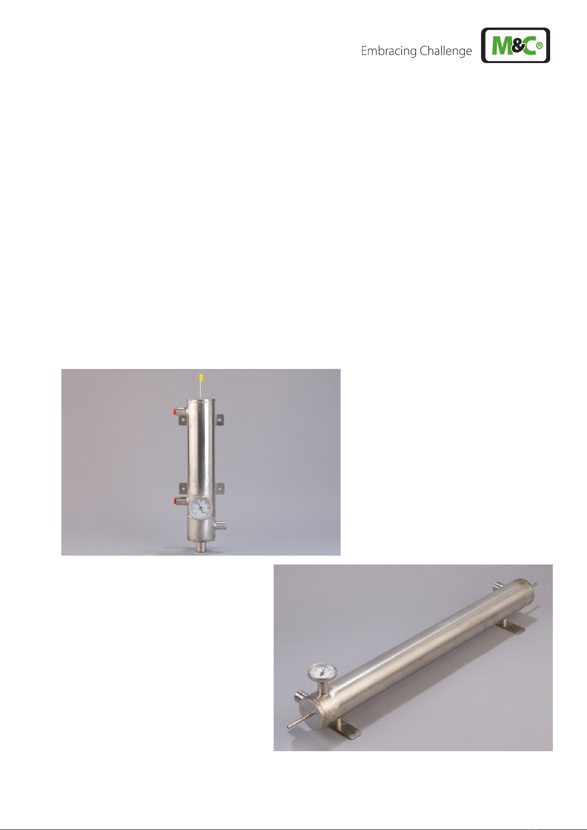
Figure 1 Gas cooler LGT-2 with tube bundle for the sample gas.........................................................................................................8
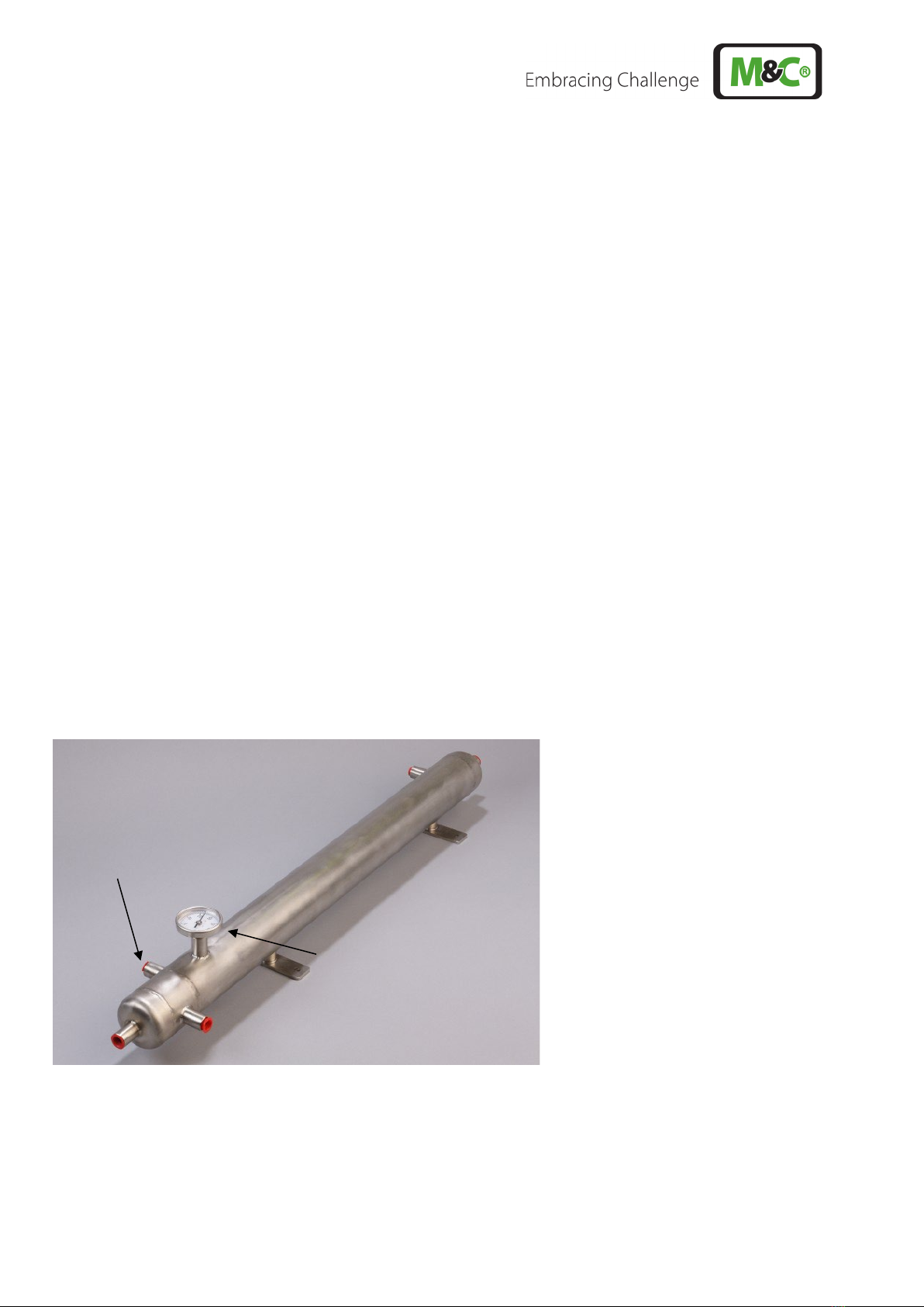
Figure 2 Liquid cooler LC-1 with cooling coil for the liquid sample...................................................................................................9
Figure 3 Dimensions: gas cooler LGC-1(S).......................................................................................................................................................12
Figure 4 Dimensions: gas cooler LGT-2.............................................................................................................................................................12
Figure 5 Dimensions: liquid cooler LC-1(S) .....................................................................................................................................................13
Figure 6 Dimensions: liquid cooler LTC-1 ........................................................................................................................................................13

4 LC, LG, LT | 1.00.01 www.mc-techgroup.com
Head Office
M&C TechGroup Germany GmbH Rehhecke 79 40885 Ratingen Germany
Telephone: 02102 / 935 - 0
Fax: 02102 / 935 - 111
E - mail: info@mc-techgroup.com
www.mc-techgroup.com
1General Information
The product described in this operating manual has been examined before delivery and left our works in perfect
condition related to safety regulations. In order to keep this condition and to guarantee a safe operation, it is
important to heed the notes and prescriptions made in this operating manual. Furthermore, attention must be paid
to appropriate transportation, correct storage, as well as professional installation and maintenance work.
All necessary information a skilled staff will need for appropriate use of this product are given in this operating
manual.
2Declaration of conformity
The product described in this operating manual complies with the following EU directives:
RoHS Directive
The requirements of the RoHS2 (‘Restriction of Hazardous Substances 2’) directive 2011/65/EU and its annexes are
met.
Simple pressure vessels
The manufacturer warrants that the liquid chillers described herein, have a product PS × V of not more than 50
bar liters, and therefore have been designed and manufactured in accordance with Directive 2014/29/EU in
accordance with engineering practice recognized as sound in an EU Member State.

www.mc-techgroup.com LC, LG, LT | 1.00.01 5
3Safety instructions
Follow these basic safety procedures when mounting, commissioning or operating this equipment:
•These instruction manual points out the basic dangers when handling the cooler. Further system-related
hazards may occur in individual cases, which the operator must evaluate according to his hazard
assessment - and take appropriate measures.
•Read the instruction manual before commissioning and use. The notes and warnings in the operating
instructions must be complied with.
•When connecting the cooler, ensure that the correct pressure ranges are used in accordance with the type
plate specifications or technical data.
•Before opening the cooler, it must be depressurized. This also applies to any external connections that may
be connected.
•Only use the cooler within the permissible temperature and pressure ranges. The permissible temperature
and pressure ranges are described in the corresponding technical data.
•Ensure that the device is installed in a weather-protected location. Do not expose directly to rain or liquids.
•The cooler must not be operated in potentially explosive atmospheres; The cooler must only be operated
with sample gas according to the analysis questionnaire.
•The cooler must not be operated in potentially explosive atmospheres; The cooler must only be operated
with sample gas according to the analysis questionnaire.
•If the cooler is used to cool gases that are harmful to health, appropriate safety measures must be taken in
the event of leaks (e.g. leaking connections). The personal protective equipment must be adapted to the
hazards at the place of installation and sampling.
•The cooler must be adequately protected against corrosive influences, shocks and impacts to prevent
leakage and component failure.
•Inlets and outlets of the cooler must be provided with protective plugs. This measure is necessary to protect
the interior from corrosion and to prevent the escape of residual liquid or the ingress of foreign bodies.
•Only gases which cannot react with each other or with the material of the cooler or the connections in any
form can be cooled in the cooler.
4Warranty
If the equipment fails, please contact M&C directly or else go through your M&C authorised dealer.
We offer a one year warranty as of the day of delivery as per our normal terms and conditions of sale, and
assuming technically correct operation of the unit. Consumables are hereby excluded. The terms of the warranty
cover repair at the factory at no cost or the replacement at no cost of the equipment free ex user location.
Reshipments must be sent in a sufficient and proper protective packaging.

6 LC, LG, LT | 1.00.01 www.mc-techgroup.com
5Used terms and signal indications
Danger
The ‘Danger’ warning sign indicates that death, serious injury and/or
significant material damage will be the consequence, if the appropriate
precautions should not be taken.
Warning
The ‘Warning’ warning sign indicates that death, serious injury or damage to
property may occur if the relevant precautionary measures are not observed.
Caution
The ’Caution’ warning sign indicates that slight personal injury can occur if
the appropriate safety precautions are not observed.
Caution
’Caution‘ indicates that damage to property can occur if the appropriate
safety precautions are not observed.
Attention
‘Attention’ indicates that an unintended result or situation can occur if the
corresponding information is not taken into account.
Note
‘Note’ indicates important information relating to the product or highlights
parts of the documentation for special attention.
Qualified personnel
‘Qualified personnel’ are experts who are familiar with the installation,
commissioning, maintenance, and operation of these types of products. The
following knowledge is at least required for the work:
•Trained person in the process engineering field
•Detailed knowledge of the manual and the applicable safety regulations
Hot surface!
Contact may cause burn! Do not touch!
Toxic!
Acute toxicity (oral, dermal, inhalation)! Toxic when in contact with skin,
swallowed or inhaled.
Corrosive!
These substances destroy living tissue and equipment upon contact.
Do not breathe vapors; avoid contact with skin and eyes.
Wear protective gloves!
Working with chemicals, sharp objects or extreme
ly high temperatures
requires wearing protective gloves.

www.mc-techgroup.com LC, LG, LT | 1.00.01 7
Wear safety glasses!
Protect your eyes while working with chemicals or sharp objects. Wear
safety glasses to avoid getting something in your eyes.
Wear protective clothes!
Working with chemicals, sharp objects or extreme
ly high temperatures
requires wearing protective clothes.

8 LC, LG, LT | 1.00.01 www.mc-techgroup.com
6Introduction
The M&C gas coolers LGC-1 (with cooling coil for sample gas), LGC-1S (with longer cooling coil for sample gas) and
LGT-2 (with tube bundle for sample gas) are used in analytical technology to lower the dew point of humid sample
gases.
The M&C liquid coolers LC-1 (with cooling coil for liquid sample), LC-1S (with longer cooling coil for liquid sample)
and LTC-1 (with tube bundle for liquid sample) are used to reduce the temperature of liquid media.
Water, for example, is used as the coolant. The counterflow principle used ensures maximum cooling effect.
6.1 Serial number
The type plate with the serial number is located at the side panel of the cooler housing. Whenever you call M&C
regarding questions or orders for the spare parts please give us the serial number of the device.
7Description
The M&C gas coolers LGC-1 and LGC-1S are designed with a cooling coil fully welded in the jacket tube. The LGC-
1S version is equipped with a longer cooling coil.
An integrated separation chamber in the lower part of the gas cooler ensures optimum condensate separation.
In the LGT-2 gas cooler, the sample gas flows through a tube bundle; here, too, there is a separation chamber in
the lower part of the gas cooler for condensate separation.
Figure 1 Gas cooler LGT-2 with tube bundle for the sample gas
A dial thermometer is positioned in the coolant inlet of the gas cooler (coolant IN), which can be used to indicate
the gas outlet dew point.
The condensate produced is discharged externally by using peristaltic pumps, traps or collecting vessels.
Coolant IN
Dial thermometer

www.mc-techgroup.com LC, LG, LT | 1.00.01 9
The M&C liquid coolers LC-1 and LC-1S are designed with a cooling coil fully welded in the jacket tube. The LC-1S
version is equipped with a longer cooling coil.
Figure 2 Liquid cooler LC-1 with cooling coil for the liquid sample
A dial thermometer is positioned in the coolant inlet of the LC-1 and LC-1S liquid coolers (coolant IN).
In the LTC-1 liquid cooler, the liquid sample flows through a tube bundle. There is a distribution chamber in each
of the inlet and outlet areas of the tube bundle. The distribution chamber in the upper part of the tube bundle is
screwed to the liquid cooler and can be detached.
The dial thermometer of the LTC-1 liquid cooler is located in the sample outlet (see Figure 6). The dial thermometer
can be used to indicate the sample outlet temperature.
The gas and liquid coolers of the LC, LG and LT series operate with low maintenance.
The cooling effect and the stability of the cooling depend, among other things, on the coolant inlet temperature,
the coolant quantity, the sample inlet conditions, the aggregate state of the liquid sample to be cooled, ∆T
between coolant inlet temperature and sample outlet temperature as well as the ambient temperature.
The existing coolant quality and the liquid sample to be cooled must correspond with the material specification
of the cooler.
Coolant IN
Dial thermometer

10 LC, LG, LT | 1.00.01 www.mc-techgroup.com
8Technical Data
8.1 Gas Cooler
Gas Cooler
LGC-1
LGC-1S
LGT-2
Part No.
04K1000
04K1500
04K4000
Max. cooling capacity approx.
900 kJ/h
1600 kJ/h
3600/6100 kJ/h1)
Dimension cooling coil
1 x 4/6 mm
1 x 4/6 mm
-
Cooling coil length
3.5 m [≈ 11.5 ft]
6 m [≈ 19.7 ft]
-
Dimension tube bundle
-
-
9 x 6/8 mm
Tube bundle length
-
-
0.6 m [≈ 2.0 ft]
Connection A (Sample gas IN)
Tube ø 6 mm
Tube ø 6 mm
G 3/8" i
Connection B (Sample gas OUT)
G 1/4" i
G 1/4“ i
G 3/8" i
Connection C (Condensate OUT)
G 3/8" i
G 3/8“ i
G 3/8" i
Connection D/E (Coolant
IN/OUT).
G 1/4" i
G 1/4“ i
G 3/8" i
Sample flow rate, recommended
max.
500 Nl/h
500 Nl/h
700 Nl/h
Max. sample pressure
10 bar
10 bar
10 bar
Max. coolant pressure
10 bar
10 bar
10 bar
Coolant liquid flow rate
50 to 300 l/h, depending on necessary cooling capacity, coolant
temperature IN/OUT, etc.
Differential pressure ∆P sample
side
30 mbar at 500 l/h
30 mbar at 500 l/h
< 1 mbar at 500 l/h
Stagnant space sample side
175 ml
210 ml
370/780 ml1)
Max. sample inlet temperature
300 °C [572 °F]
300 °C [572 °F]
300 °C [572 °F]
Ambient temperature
+2 to +80 °C [35.6 to 176 °F]
Storage temperature
-40 to +80 °C [-40 to 176 °F]
Mounting
Wall-mount
Material of sample gas-
contacted parts
Stainless steel 316Ti*
Dimensions (W x H x D)
110 x 400 x 125 mm
[≈ 4.3“ x 15.8“ x 4.9“]
110 x 700 x 125 mm
[≈ 4.3“ x 27.6“ x 4.9“]
120 x 750 x 125 mm
[≈ 4.7“ x 29.5“ x 4.9“]
Weight
1.8 kg [≈ 4.0 lbs]
3 kg [≈ 6.6 lbs]
3.3 kg [≈ 7.3 lbs]
Options for gas cooler LGT-2
(jacket cooler with tube bundle)
Part No.
Pressure rating PN40 with certificate of conformity
04K9000
Tube bundle: tube diameter 10/12 mm1) instead of 6/8 mm
04K9010
Connection A/B/C/D (Sample gas IN/OUT, Condensate OUT, Coolant IN/OUT):
G 1/4“ i instead of G3/8“ i
04K9035
Connection A/B/C/D (Sample gas IN/OUT, Condensate OUT, Coolant IN/OUT):
G 1/2“ i instead of G3/8“ i
04K9040
1) = With option tube bundle diameter 10/12 mm instead of 6/8 mm.
* = Standard, others on request.
Maximum cooling capacity refer to over-heated vapor or liquid and sufficient coolant.

www.mc-techgroup.com LC, LG, LT | 1.00.01 11
8.2 Liquid Cooler
Liquid cooler
LC-1
LC-1S
LTC-1
Part No.
04K2000
04K2500
04K3000
Max. cooling capacity approx.
900 kJ/h
1600 kJ/h
3600/6100 kJ/h1)
Dimension cooling coil
1 x 4/6 mm
1 x 4/6 mm
-
Cooling coil length
3.5 m [≈ 11.5 ft]
6 m [≈ 19.7 ft]
-
Dimension tube bundle
-
-
9 x 6/8 mm
Tube bundle length
-
-
0.5 m [≈ 1.6 ft]
Connection A (Liquid sample IN)
Tube ø 6 mm
Tube ø 6 mm
G 1/4" i
Connection B (Liquid sample OUT)
Tube ø 6 mm
Tube ø 6 mm
G 1/4" i
Connection C (Condensate OUT)
-
-
-
Connection D/E (Coolant IN/OUT).
G 3/8“ i
G 3/8“ i
G 3/8" i
Liquid sample flow rate,
recommended max.
60 Nl/h
60 Nl/h
200 Nl/h
Max. sample pressure
50 bar
50 bar
10 bar
Max. coolant pressure
10 bar
10 bar
10 bar
Coolant liquid flow rate
50 to 300 l/h, depending on necessary cooling capacity, coolant
temperature IN/OUT, etc.
Differential pressure ∆P sample
side
700 mbar at 60 l/h
700 mbar at 60 l/h
10 mbar at 200 l/h
Stagnant space sample side
44 ml
76 ml
350/740 ml1)
Max. sample inlet temperature
300 °C [572 °F]
300 °C [572 °F]
300 °C [572 °F]
Ambient temperature
+2 °C bis +80 °C [35.6 to 176 °F]
Storage temperature
-40 °C bis +80 °C [-40 to 176 °F]
Mounting
Wall-mount
Material of liquid sample-
contacted parts
Stainless steel 316Ti *
Dimensions (W x H x D)
110 x 400 x 125 mm
[≈ 4.3“ x 15.8“ x 4.9“]
110 x 700 x 125 mm
[≈ 4.33“ x 27.6“ x 4.9“]
120 x 650 x 125 mm
[≈ 4.7“ x 25.6“ x 4.9“]
Weight
1.8 kg [≈ 4.0 lbs]
3 kg [≈ 6.6 lbs]
3.6 kg [≈ 7.9 lbs]
Options for liquid cooler LTC-1
(jacket cooler with tube bundle)
Part No.
Pressure rating PN40 with certificate of conformity
04K9000
Tube bundle: tube diameter 10/12 mm1) instead of 6/8 mm
04K9010
Connection D/E (Coolant IN/OUT): G 1/4“ i instead of G 3/8“ i
04K9015
Connection D/E (Coolant IN/OUT): G 1/2“ i instead of G 3/8“ i
04K9020
Connection A/B (Liquid sample IN/OUT): G 3/8“ i instead of G 1/4“ i
04K9025
Connection A/B (Liquid sample IN/OUT): G 1/2“ i instead of G 1/4“ i.
04K9030
1) = For tube bundle option: 10/12 mm instead of 6/8 mm.
* = Standard, others on request.
The specified performance values refer to liquid and sufficient coolant.

12 LC, LG, LT | 1.00.01 www.mc-techgroup.com
8.3 Gas Cooler Dimensions
Figure 3 Dimensions: gas cooler LGC-1(S)
Figure 4 Dimensions: gas cooler LGT-2
A Sample gas IN
B Sample gas OUT
C Condensate OUT
D Coolant IN
E Coolant OUT
A Sample gas IN
B Sample gas OUT
C Condensate OUT
D Coolant IN
E Coolant OUT

www.mc-techgroup.com LC, LG, LT | 1.00.01 13
8.4 Liquid Cooler Dimensions
Figure 5 Dimensions: liquid cooler LC-1(S)
Figure 6 Dimensions: liquid cooler LTC-1
A Liquid sample IN
B Liquid sample OUT
D Coolant IN
E Coolant OUT
A Liquid sample IN
B Liquid sample OUT
D Coolant IN
E Coolant OUT

14 LC, LG, LT | 1.00.01 www.mc-techgroup.com
9Reception and Storage
Note
The cooler must be stored in a weather protected frost-free area!
During transport and storage, the cooler
should always be positioned and stored
according to the position indicated on the packaging.
10 Preparation for Installation
Select the optimum installation site in accordance with the generally applicable guidelines or consult the
responsible authorities. The installation of the cooler must be planned by the installer or operator.
Ensure that the cooler is easily accessible so that any maintenance work that may be necessary later can be
carried out without any problems.
11 Mounting the Cooler
The cooler is designed for stationary use and, if properly selected and installed, guarantees long service life and
minimum maintenance.
Shut-off control devices must be provided by the customer in the inlet of the coolant and the sample to be
cooled.
Note
Ensure the tightness of the tube fitting!
Check the tightness of all tubes after they have been connected.
Do not reduce the specified condensate tubing cross-sections. Reduced cross-
sections might impair the condensate drainage (if present).
12 Connecting Coolant and sample to be Cooled
Warning
Incorrect pressure can destroy the cooler.
When connecting, pay attention to the correct pressure specifications
according to the technical data and the type plate!
The device must be grounded and the potential equalization with the system
must be established.
Connect the coolant and the sample to be cooled according to the technical data and the drawings in chapter 8.

www.mc-techgroup.com LC, LG, LT | 1.00.01 15
13 Commissioning
Qualified personnel
The work described in this chapter needs to be performed by qualified
personnel. The following minimum knowledge is required for the work:
•Instructed person in the process engineering field.
•
Detailed knowledge of the operating instructions and the applicable
safety regulations.
Note
Check the tightness of the tube fitting!
If necessary, include the tightness of the tube fittings in the maintenance
cycle.
Warning
If toxic or oxygen-displacing gases are cooled with the cooler, the gas paths
must be purged with inert gas or air before opening the gas-carrying parts.
The cooling circuit should always be connected and put into operation first,
and then the sample circuit.
Caution hot surfaces possible!
If hot media are fed through the cooler, the operator must check whether the
external surfaces are to be marked with the "Caution hot" pictogram.
Furthermore, the work safety regulations of the operator must be observed.
Before commissioning, check that the pressure specification corresponds to the specifications on the type plate.
13.1 Setting the Temperature
To set the desired temperature, proceed in the following order:
1. Apply the coolant.
2. Apply the sample to be cooled.
3. Wait until a stable temperature has been reached.
4. Increase or reduce the coolant quantity to set the desired temperature.
Warning
For temperatures > 95 °C, a sufficient coolant flow must be ensured.

16 LC, LG, LT | 1.00.01 www.mc-techgroup.com
14 Closing Down
Danger
E
scape of potentially harmful gas from open process connections after
disassembly possible.
The relevant safety regulations must be observed for the media to be
conveyed.
Before opening flush the lines with a suitable inert gas.
Aggressive condensate possible!
Chemical burns caused by aggressive media possible!
For general
electrical and mechanical work on the cooler, wear personal
protective equipment (PPE) in accordance with the risk assessment.
Before decommissioning, the cooler should be purged with inert gas or air to prevent condensation of aggressive
components from the process gas.
To shut down the cooler, observe the following sequence:
1. Switch off the sample to be cooled.
2. Switch off the coolant.

www.mc-techgroup.com LC, LG, LT | 1.00.01 17
15 Maintenance
The safety instructions specific to the plant and process are to be consulted prior to any maintenance work!
Qualified personnel
The work described in this chapter needs to be performed by qualified
personnel. The following minimum knowledge is required for the work:
•Instructed person in the process engineering field.
•
Detailed knowledge of the operating instructions and the applicable
safety regulations.
Note
Check the tightness of the tube fitting!
If necessary, include the tightness of the tube fittings in the maintenance cycle.
Warning
If toxic or oxygen-displacing gases are cooled with the cooler, the gas paths
must be purged with inert gas or air before opening the gas-carrying parts.
Furthermore, the work safety regulations of the operator must be observed.
Aggressive condensate possible!
Chemical burns caused by aggressive media possible!
High surface temperatures possible! Touching the device can cause severe
burns!
For general electrical and mechanical work on the cooler, wear personal
protective equipment (PPE) in accordance with the risk assessment.
The intervals between servicing are dependent on the process and system conditions in your facility. The facility
QA/QC plan should address the frequency for maintenance and should be updated based on your operations.

18 LC, LG, LT | 1.00.01 www.mc-techgroup.com
16 Proper disposal of the device
At the end of the life cycle of our products, it is important to take care of the appropriate disposal of obsolete
electrical and non-electrical devices. To help protect our environment, please follow the rules and regulations of
your country regarding recycling and waste management.
17 Appendix
Further product documentation can be seen and downloaded from our home page:
www.mc-techgroup.com
This manual suits for next models
8
Table of contents
Other M&C Accessories manuals