M&C ECM Series User manual

Electric Gas Cooler Series EC®
ECM
Instruction Manual
Version 1.01.00

2 ECM | 1.01.00 www.mc-techgroup.com
Dear customer,
Thank you for buying our product. In this instruction manual you will find all necessary information about
this M&C product. The information in the instruction manual is fast and easy to find, so you can start
using your M&C product right after you have read the manual.
If you have any question regarding the product or the application, please don’t hesitate to contact M&C
or your M&C authorized distributor. You will find all the addresses in the appendix of this manual.
For additional information about our products and our company, please go to M&C’s website www.mc-
techgroup.com. There you will find the data sheets and manuals of all our products in German and
English.
This Operating Manual does not claim completeness and may be subject
to technical modifications.
© 09/2018 M&C TechGroup Germany GmbH. Reproduction of this
document or its content is not allowed without permission from M&C
Version: 1.01.00

www.mc-techgroup.com ECM | 1.01.00 3
Content
1General information................................................................................................................ 4
2Declaration of conformity....................................................................................................... 4
3Safety instructions.................................................................................................................. 5
4Warranty .................................................................................................................................. 5
5Used terms and signal indications ........................................................................................ 6
6Introduction............................................................................................................................. 8
6.1 Serial number ........................................................................................................................ 8
7Application .............................................................................................................................. 8
8Technical Data......................................................................................................................... 9
8.1 For basic cooler ECM without heat exchanger....................................................................... 9
8.2 Options for basic cooler ECM............................................................................................... 10
9Description............................................................................................................................ 10
10 Function................................................................................................................................. 11
11 Reception and storage.......................................................................................................... 12
12 Installation instructions........................................................................................................ 13
13 Supply connections.............................................................................................................. 13
13.1 Hose connections ................................................................................................................ 13
13.2 Electrical connections .......................................................................................................... 15
14 Start-up.................................................................................................................................. 16
15 Closing down......................................................................................................................... 16
16 Maintenance .......................................................................................................................... 17
16.1 Adding and replacing the heat exchangers .......................................................................... 17
16.2 Cleaning the fins of the condenser....................................................................................... 18
16.3 Maintenance of the optional mounted peristaltic pump(s), type SR25.2............................... 18
16.3.1 Mounting instructions for SR25.2 peristaltic pump (optional)......................................... 18
16.3.2 Change of the pump tube.............................................................................................. 19
16.3.3 Change of contact pulleys and springs.......................................................................... 20
16.3.4 Cleaning the pump head............................................................................................... 21
17 Operating of the built-in electronic temperature controller ............................................... 21
17.1 Changing the set value ........................................................................................................ 21
17.2 Changing the temperature alarm range................................................................................ 22
18 Trouble shooting................................................................................................................... 22
19 Spare parts list...................................................................................................................... 23
20 Appendix................................................................................................................................ 24
List of illustrations
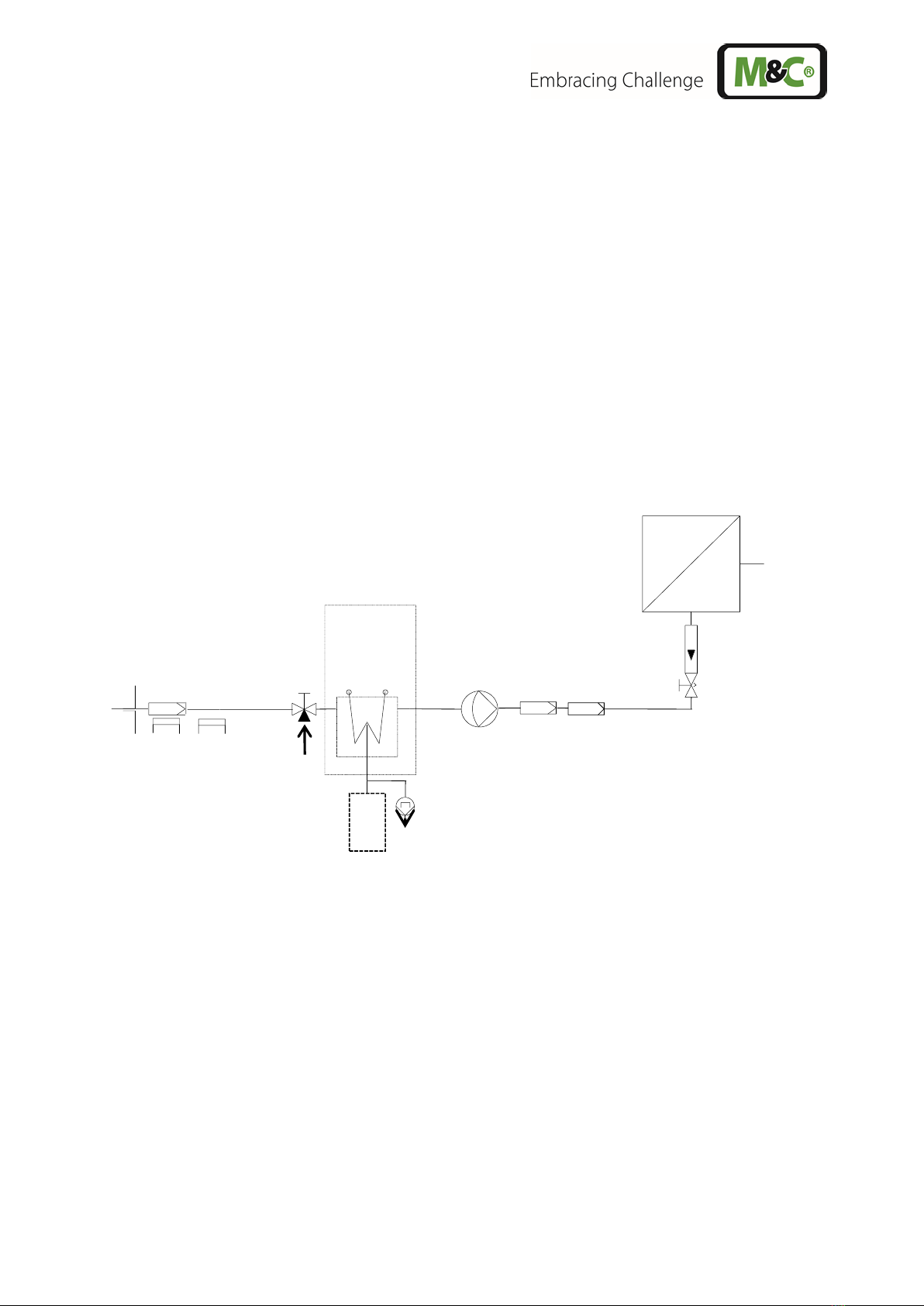
Figure 1 Application example of the ECM..................................................................................... 8
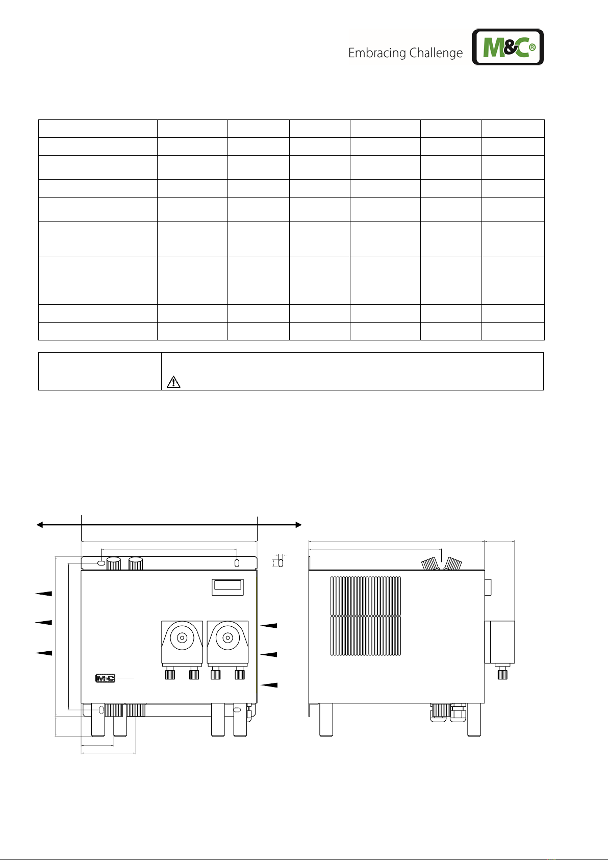
Figure 2 ECM-2G........................................................................................................................ 10
Figure 3 Schematic diagram of the heat exchanger function....................................................... 12
Figure 4 Gas and condensate connections................................................................................. 13
Figure 5 Electrical sockets alarm contact.................................................................................... 15
Figure 6 SR25.2: Mounting distance between front panel and pump motor ................................ 19
Figure 7 Change of the pump tube ............................................................................................. 20
Figure 8 Front view of the temperature controller........................................................................ 21
Figure 9 Dependency of gas outlet dew point at a gas inlet point of 60 °C [140 °F] .................... 24
Figure 10 Circuit diagram ECM (drawing No.: 2456-5.01.0).......................................................... 25
Figure 11 ECM compressor connection........................................................................................ 26

4 ECM | 1.01.00 www.mc-techgroup.com
Head Office
M&C TechGroup Germany GmbH Rehhecke 79 40885 Ratingen Germany
Telephone: 02102 / 935 - 0
Fax: 02102 / 935 - 111
E - mail: info@mc-techgroup.com
www.mc-techgroup.com
1 GENERAL INFORMATION
The product described in this operating manual has been examined before delivery and left our works
in perfect condition related to safety regulations. In order to keep this condition and to guarantee a safe
operation, it is important to heed the notes and prescriptions made in this operating manual.
Furthermore, attention must be paid to appropriate transportation, correct storage, as well as
professional installation and maintenance work.
All necessary information a skilled staff will need for appropriate use of this product are given in this
operating manual.
2 DECLARATION OF CONFORMITY
CE - Certification
The product described in this operating manual complies with the following EU directives:
EMV-Instruction
The requirements of the EU directive 2014/30/EU ‘Electromagnetic compatibility’ are met.
Low Voltage Directive
The requirement of the EU directive 2014/35/EU ‘Low Voltage Directive’ are met.
The compliance with this EU directive has been examined according to DIN EN 61010.
Declaration of conformity
The EU Declaration of conformity can be downloaded from the M&C homepage or directly requested
from M&C.
CSA - Certification
The product described in this operating manual complies with the following CSA directive:
CAN/CSA-C22.2 No.61010.1-04 UL Std.61010-1 (2 Edition).

www.mc-techgroup.com ECM | 1.01.00 5
3 SAFETY INSTRUCTIONS
Please take care of the following basic safety procedures when mounting, starting up or
operating this equipment:
•Read this operating manual before starting up and use of the equipment. The information and
warnings given in this operating manual must be heeded.
•Any work on electrical equipment is only to be carried out by trained specialists as per the
regulations currently in force.
•Attention must be paid to the requirements of VDE 0100 (IEC 364) when setting high-power
electrical units with nominal voltages of up to 1000 V, together with the associated standards
and stipulations.
•Check the details on the type plate to ensure that the equipment is connected to the correct
mains voltage.
•Protection against touching dangerously high electrical voltages:
Before opening the equipment, it must be switched off and hold no voltages. This also applies to
any external control circuits that are connected.
•The device is only to be used within the permitted range of temperatures and pressures.
•Check that the location is weather-protected. It should not be subject to either direct rain or
moisture.
•The gas cooler ECM must not be used in hazardous areas.
•Installation, maintenance, monitoring and any repairs may only be done by authorized personnel
with respect to the relevant stipulations.
4 WARRANTY
If the equipment fails, please contact M&C directly or else go through your M&C authorised dealer.
We offer a one year warranty as of the day of delivery as per our normal terms and conditions of sale,
and assuming technically correct operation of the unit. Consumables are hereby excluded. The terms
of the warranty cover repair at the factory at no cost or the replacement at no cost of the equipment free
ex user location. Reshipments must be send in a sufficient and proper protective packaging.

6 ECM | 1.01.00 www.mc-techgroup.com
5 USED TERMS AND SIGNAL INDICATIONS
Danger
The ‘Danger’ warning sign indicates that death, serious injury and/or
significant material damage will be the consequence, if the
appropriate precautions should not be taken.
Warning
The ‘Warning’ warning sign indicates that death, serious injury or
damage to property may occur if the relevant precautionary
measures are not observed.
Caution
The ’Caution’ warning sign indicates that slight personal injury can
occur if the appropriate safety precautions are not observed.
Caution
’Caution‘ indicates that damage to property can occur if the
appropriate safety precautions are not observed.
Attention
‘Attention’ indicates that an unintended result or situation can occur
if the corresponding information is not taken into account.
Note
‘Note’ indicates important information relating to the product or
highlights parts of the documentation for special attention.
Qualified personnel
‘Qualified personnel’ are experts who are familiar with the
installation, mounting, commissioning and operation of these types
of products.
High voltages!
Protect yourself andothers againstdamages which might becaused
by high voltages.
Toxic!
Acute toxicity (oral, dermal, inhalation)! Toxic when in contact with
skin, swollowed or inhaled.
Corrosive!
These substances destroyliving tissue and equipment upon contact.
Do not breathe vapors; avoid contact with skin and eyes.
Contains gas under pressure. Do not open container!
Check pressure before opening container, and adjust pressure to
atmosheric pressure.

www.mc-techgroup.com ECM | 1.01.00 7
Wear protective gloves!
Working with chemicals, sharpe objects or extremly high
temperatures requires wearing protective gloves.
Wear safety glasses!
Protect your eyes while working with chemicals or sharpe objects.
Wear safety glasses to avoid getting something in your eyes.
Wear protective clothes!
Working with chemicals, sharpe objects or extremly high
temperatures requires wearing protective clothes.

8 ECM | 1.01.00 www.mc-techgroup.com
6 INTRODUCTION
The M&C cooler ECM is used for applications where interfering moisture loading in the sample gas is
to be expected.
By lowering to a very low stable dew point, condensation is prevented in the analyzer and a fluctuating
measurement value due to water vapour cross sensitivities or volumetric errors is avoided.
6.1 SERIAL NUMBER
The type plate with the serial number is located at the side panel of the cooler housing (wall mounting
version). Whenever you call M&C regarding questions or orders for the spares please give us the serial
number of your ECM.
7 APPLICATION
Figure 1 shows a typical example of an application for installation of an ECM gas cooler unit.
Sample gas inlet
+5°C
[41 °F]
ECM-1
Alternative :
Collecting vessel
Test gas
IN
Figure 1 Application example of the ECM
1: Filter sample probe SP ...
2: Heating sample line
3: ECM cooler
4: 3-way ball valve
5: Peristaltic pump (option)
6: Membrane pump
7: Super fine filter FP ...
8: Aerosol filter CLF-5
9: Flow meter FM10
10 : Analyzer
The gas to be measured is taken from the ECM gas cooler by a gas sample probe via a heated
sample line andcooled down to adew point of +5 °C[41 °F].Thesuper-finefilter located afterwards
removes solid particles. For increased operating safety of the entire system we recommend installing a
super-fine filter with a liquid alarm sensor. If required an aerosol filter can be installed in front of
the flow meter . The gas thus treated can now be passed into the analyzer .

www.mc-techgroup.com ECM | 1.01.00 9
8 TECHNICAL DATA
8.1 FOR BASIC COOLER ECM WITHOUT HEAT EXCHANGER
Gas cooler series EC
Version ECM-1
Version ECM-2
Part No.
02 K 7500 (a)**
02 K 7510 (a)**
Number of heat exchanger
possibility
prepared for 1 stream
prepared for 2 streams
Sample outlet dew point
range of adjustment: +2 °C ..... +7 °C [35.6 °F …44.6 °F], factory
setting: +5 °C [41 °F]
Dew point stability
at const. conditions: < ±0.1 °C [±0.18 °F]
Sample inlet temperature
***max. +180 °C [356 °F]
Sample inlet dew point
***max. +80 °C [176 °F]
Gas flow rate
***max. 250 l/h
***max. 2x150 l/h
Ambient temperature
+10 °C to +50 °C [50 °F to 122 °F]
Storage temperature
-20 to +60 °C [~-4 °F to 140 °F]
Total cooling capacity
40 W at 10 °C –50 °C [50 °F to 122 °F] ambient temperature
Ready for working
< 15 min
Power consumption
max. 200 VA (start up current at 230 V=2.5 A; at 120 V=4.5 A)
Main power connection
240 V/120 V, 50 Hz / 60 Hz (a) :-15 % / +10 %
Electrical connections
terminals: 6-12 mm , cable gland: 2 x M20 x 1,5
Status alarm
1 free configurable status alarm with 2 potential free change-over
contacts, alarm point: < 2°C [35.6 °F] and > 8 °C [46.4 °F]
contact rating 250 VAC, 2 A; 500 VA; 50 W
Electrical safety
EN
EN 61010
CAN/CSA-C22.2 No.61010.1-04
UL Std. No. 61010-1(2 Edition)
System of protection
IP20 (EN 60529)
Case colour
RAL 9003
Method of mounting
wall mounting
Dimensions
Weight
270 x 270 x 316 mm [10.63” x 10.63” x 12.44”] (W x H x D)
12 kg [26.46 lbs] /13.5 kg [29.76 lbs] (version: 230 V / 115 V)
** Option
*** Maximum values in technical data must be rated in consideration of total cooling capacity at 25 °C [77 °F] ambient
temperature and an outlet dew point of 5 °C [41 °F].

10 ECM | 1.01.00 www.mc-techgroup.com
8.2 OPTIONS FOR BASIC COOLER ECM
Heat exchanger type
ECM-1G
ECM-1PV
ECM-1SS
ECM-2G
ECM-2PV
ECM-2SS
Part No
93 K 0140
93 K 0170
93 K 0160
97 K 0100
97 K 0110
97 K 0115
Material of heat
exchanger
Borosilicate
glass
PVDF
st. steel
316Ti
Borosilicate
glass
PVDF
st. steel
316Ti
Max. gas flow rate
250 Nl/h
250 Nl/h
250 Nl/h
150 Nl/h
150 Nl/h
150 Nl/h
Sample gas pressure
abs.
max. 2 bar (3
bar)1
max. 3 bar
max. 10
bar
max. 2 bar (3
bar)1
max. 3 bar
max. 10 bar
Sample gas connection
GL18
for Ø6 mm
a.d. tube*
G1/4“i
G1/4“i
or 1/4“
NPT**
GL18
for Ø6 mm
a.d. tube*
Tube
Ø6 mm*
Tube
Ø6 mm*
Condensate connection
GL25 for Ø12
mm tube*
Ø8 mm or
Ø10 mm**
G3/8“i
G3/8“i o.
3/8“NPT**
GL25 for Ø12
mm tube*
Ø8 mm or
Ø10 mm**
G3/8“i
G3/8“i o.
3/8“NPT**
P at max. flow
1 mbar
1 mbar
1 mbar
1 mbar
1 mbar
1 mbar
Stagnant space approx.
100 ml
100 ml
100 ml
40 ml
25 ml
30 ml
Peristaltic pump SR25.2
1 pc. incorporated in the cooler, compl. installed, part no.: 01 P 9125; cooler weight
plus 0.6 kg (1.32 lb) per pump
the sample gas pressure is limited to 2 bar absolute
* Standard, other version on request 1with GL connecting adapter
** Option
*** Maximum values in technical data must be rated in consideration of total cooling capacity at 25 °C [77 °F] ambient
temperature and an outlet dew point of 5 °C [41 °F].
9 DESCRIPTION
Figure 2 shows the ECM-2G cooler unit.
Min. side distance
100
(3.94“)
100
(3.94“)
EC
M
Cooler
220
(8.66“)
240
(9.45“)
30
(1.18“)
208 (8.19“)
270 (10.63“)
204 (8.03“)
270(10.63“)
46
(1.81“)
11
(0.43“)
6 (0.24“)
84
(3.31“)
50
(1.97“)
ventilation
opening
Compressor
ventilation outlet
Dimensions in mm (Inch)
Figure 2 ECM-2G

www.mc-techgroup.com ECM | 1.01.00 11
The cooler ECM is equally suitable for wall installation. The depth of the housing of the cooler is 270
mm [10.63”] (316 mm [12.44”] with optional mounted peristaltic pumps).
On the upper side of the cooler casing you will see the cutouts for 1 or 2 heat exchangers. Sample gas
enters and leaves the heat exchangers by the correspondingly connectionson the upper part of the heat
exchangers (see 8. technical data).
The main power connector and the contact output for the status alarm can be connected at terminals
X1 respectively X3 located behind the removable front panel of the ECM housing.
At the bottom of the housing the following connections are provided as standard:
•standard condensate outlets from the heat exchangers,
•cable bushings 2 x M20 x 1.5 clamp range 6-12 mm;
With under- respectively ambient pressure the condensate removal happens via the peristaltic pumps
SR25.2 optionally implemented in the cooler housing or externally with collecting vessels type
TG.../TK... . With over-pressure an automatic liquid drainer type AD-... is suitable.
10 FUNCTION
The M&C gas cooler type ECM is a compressor cooler with status alarm capability. This ensures 100%
availability of the cooler.
Up to 2 Jet-stream heat exchangers made of Borosilicate glass, PVDF or stainless steel are located in
a heat-insulated cooling block. All the heat exchangers are easily accessible and are arranged in such
a way that they can be removed very simply.
Figure 3 shows a schematic diagram of the functioning of the heat exchanger: The compressor cooler
system has a heat-insulated cooling block at a constant temperature of +5 °C [41 °F]. The novel
construction of the heat exchanger guarantees a very good pre-separation of condensate and for that
reason an optimal drying of sample gas.

12 ECM | 1.01.00 www.mc-techgroup.com
+5 °C
[41 °F]
Sample
OUT
Sample
IN
Condensate OUT
Cooling
block
Figure 3 Schematic diagram of the heat exchanger function
11 RECEPTION AND STORAGE
The ECM gas cooler is a complete pre-installed unit.
•Carefully inspect the ECM and any special accessories included with it immediately on arrival by
removing them from the packing and checking for missing articles against the packing list! Check
the items for any damage in transit and, if required, inform the shipping insurance company
immediately of the damage found!
Note
The cooler must be stored in a weather protected frost-free area!
During transport and when in storage, the cooler must always be stood up
with the transport feet positioned underneath so that the oil in the closed
compressor circuit cannot run out of this compressor case.
If the cooler is transported on its back by mistake, it must stood in the
operating position for approx. 24 hours before it is switched on!

www.mc-techgroup.com ECM | 1.01.00 13
12 INSTALLATION INSTRUCTIONS
The ECM cooler is suitable for wall mounting.
Note
The operating positionfor this cooler is exclusively vertical. This is the only
way to ensure proper separation and removal of condensate in the heat
exchangers. During transport and installation, the cooler must always be
stood up with the transport feet positioned underneath so that the oil in the
closed compressor circuit cannot run out of the compressor case.
The cooler should be kept away from sources of heat and well ventilated
when installed, so that condensation from warmth will not occur and
interfere with operation.
The minimum installation dimensions (fig. 2) must be followed without fail.
If the unit is installed in the open, the cooler must be installed in a housing
that is frost-free in winter and adequately ventilated in summer. Avoid
locating the unit in direct sunlight.
Unheated gas sample lines must be provided with slope up to the cooler. In
that case pre-separation of the condensate is not required. Connect the
heated sample line with sufficient thermal decoupling of min. 20 cm [7.87”]
to the cooler!
13 SUPPLY CONNECTIONS
13.1 HOSE CONNECTIONS
The connection for sample gas inlet and outlet happens on the upper part of the heat exchangers. For
possible connectors see technical data (chapter 8).
1
EC
M
Cooler
2
1Gas inlet and outlet
2Condensate outlet
3Condensate outlet with optional
mounted peristaltic pump
3
Figure 4 Gas and condensate connections
Correspondingly tube and hose connectors are optional available by M&C.

14 ECM | 1.01.00 www.mc-techgroup.com
Note
Do not mix up the hose connections; the inlet and outlet connections of the
heat exchangers are marked with arrows;
Ensure that the connections are sealed adequately;
To ensure free removal of the condensate, ensure that the listed diameters
for the condensate removal lines are not reduced!
Ensure that the connections are sealed adequately by noting the following:
Borosilicate glass heat exchangers with connections GL18-6 respectively GL25-12 (standard)
•Before assembly, check the GL coupling rings to see if the PTFE/silicon locking rings have been
damaged.
•The sealing rings should be installed with the PTFE side facing the medium.
PVDF- resp. stainless steel heat exchangers with G1/4“I resp. G3/8“I
•The correspondingly dimensioned tube respectively hose couplings with threaded connections
have to be screwed in with PTFE thread sealing tape.
•To grant a functional and unproblematic mounting we recommend to use union pieces with taper
pipe thread type R according to DIN 2999/1 in connection with suitable sealing tape.
Note
When fixing the connectors in the PVDF respectively stainless steel heat
exchanger hold up with a wrench at the pane of the bolt head!
Option: stainless steel heat exchanger with NPT
•The heat exchangers with NPT threaded connectors are marked with circulated notches.
•In order to ensure the tightness of the connections, the NPT thread must be screwed in with
sealant or fixed with adhesive.
In the standard configuration, the tubes for removal of condensate are connected directly to the heat
exchangers. These protrude with the GL25-12 tube connectors (standard, Borosilicate glass heat
exchanger) respectively with G3/8” (standard) thread joint PVDF or stainless steel heat exchanger
above the base plate of the cooler casing (fig.2).
Condensate removal is done by customer according to the type of operation with:
•peristaltic pump(s) type SR25.2 implemented optionally in the cooler housing,
•external mounted condensate vessel(s) with manually emptying respectively,
•automatic float-type condensate traps type AD-... (only for over-pressure operation).
Note
Stainless steel heat exchangers with G3/8” thread joint can be directly fitted
up with the float-type condensate trap AD-SS by means of a thread adapter
part number FF 11000 (1/2” NPT to G3/8”i). By this wall mounting and tubing
of the AD-SS unit isn’t necessary!

www.mc-techgroup.com ECM | 1.01.00 15
13.2 ELECTRICAL CONNECTIONS
When connecting the equipment, please ensure that the supply
voltage is identical with the information provided on the model type
plate!
Note
Attention must be paid to the requirements of IEC 364 (DIN VDE
0100) when setting high-power electrical units with nominal voltages
of up to 1000 V, together with the associated standards and
stipulations.
An external main switch must be provided.
The main circuit must be equipped with a fuse of 10 AT (over current
protection); for electrical details see technical data (chapter 8).
Warning
Cooler versions with 115 V resp. 120 V have a built-in transformer
to generate an internal current of 230 V. That means, device internal
live parts have a current of 230 V not 115 V/120 V.
Figure 5 shows the electrical connections at the plastic housing behind the front panel of the ECM
housing (fig. 2).
Alarm warnings for over- and under-temperature are given as a collective status alarm via a relay output
with two potential-free changeover contacts. Alarm will be released if the current temperature is out of
a range of ±3 °C [±5.4 °F] referring to the set-temperature (+5 °C [41 °F]).
Figure 5 Electrical sockets alarm contact
The connection of the mains respectively status alarm signals happens as follows:
•release the screws (7 pcs.) from the cooler top and remove it;
•put the cables (6-12 mm) through one of the cable glands and connect them according to a.m.
wiring plan;
•assembly of the housing parts is done in reverse order.

16 ECM | 1.01.00 www.mc-techgroup.com
14 START-UP
The thermo-hydraulic controlled cooling system of the ECM permit automatic start-up of the cooler.
The following description is valid for start-up of the gas cooler for an ambient temperature >+8 °C
[46.4 °F].
Note
Before starting up the gas cooler, it must be placed in its operating
position for at least two hours. The liquid inside the system may have
been redistributed, and this could cause problems in operating.
The following steps should be carried out before initial start-up:
•Connect the cooler unit to the mains power supply; Check that the equipment is connected to
the correct mains voltage, 115 V or 230 V, as shown on the type plate.
•Lead the status contact for status alarm to the measuring station;
Note
The status contacts must be connected to the external sample gas
pump or to a valve in the sample gas line to protect the entire analysis
system by immediately cutting off the gas supply in the event of error
messages from the cooler!
15 CLOSING DOWN
Note
The location for the cooler must remain frost-free, even when the unit
has been switched off!
If the cooler unit is putting out of action for a short time no particular
measures need to be taken.
We recommend sweeping the cooler with inert gas or ambient air while
the unit is putting out of action for a longer time.
Caution
Aggressive condensate is possible.
Wear protective glasses and proper protective clothing!

www.mc-techgroup.com ECM | 1.01.00 17
16 MAINTENANCE
The safety instructions specific to the plant and process are to be consulted prior to any maintenance
work!
Danger
Dangerous voltage!
It is necessary to take the gas cooler off the mains before anyassembly,
maintenance and repair work is carried out!
The ECM cooler does not require any special maintenance intervals. The cooler is to be cleaned with
compressed air according to the contamination level of the ambient air.
16.1 ADDING AND REPLACING THE HEAT EXCHANGERS
Removal of the heat exchangers may be necessary to carry out maintenance or repair work.
We recommend the following procedures and in this order for replacement of the heat exchangers:
•Release the upper gas connections and lower condensate connections;
•Pull the heat exchangers upwards with rotation out of the cooling block;
Replace the heat exchangers as follows:
•Dry and clean the push-in opening in the aluminium cooling block with a cloth;
•Smear the push-in opening with a thin and equal layer of thermal conductivity paste (part no. 90
K 0115);
•Smear the heat exchangers with a thin and equal layer over the whole surface with thermal
conductivity paste (part no. 90 K 0115) to ensure good conduction of heat. It is best to close off
the condensate removal of the heat exchangers tube with adhesive tape to prevent any of the
thermal conductivity paste from getting into the heat exchanger;
•Lightly push the heat exchangers with rotation back into the push-in opening of the cooling block
and press to the upper block;
•Remove the adhesive tape and any surplus thermal conductivity paste;
•Reconnect the hoses.
Note
Do not mix up the hose connections; gas outlet and gas inlet are
marked with arrows!
Mounting the Borosilicate glass heat exchangers please notice:
•Check the PTFE/Silicon locking rings for damage. In assembly, the locking rings must have the
PTFE side facing the medium, otherwise the required degree of sealing cannot be guaranteed!
•Hand tighten the red GL union nuts by turning them clockwise;
To ensure a safe connection of the sample gas respectively condensate tubes to the Borosilicate glass
heat exchanger(s) we recommend the use of GL-couplings.
Please feel free to contact us, if you need any help choosing the right connectors or couplings.

18 ECM | 1.01.00 www.mc-techgroup.com
16.2 CLEANING THE FINS OF THE CONDENSER
Dust on the fins of the condenser reduces the cooling capacity. Therefore it is necessary to clean the
fins from time to time. The following steps are recommended:
•Shut off the gas flow;
•disconnect the cooler from the power supply;
•disconnect sample gas inlet and outlet lines;
•Loosen the screws of the cover part and remove the cover;
•Carefully blow out the condenser fins with compressed air;
•Carefully remount the cover part;
•Connect sample gas lines
Note
Do not mix up the hose connections; the inlet and outlet connections of
the heat exchangers are marked with arrows.
16.3 MAINTENANCE OF THE OPTIONAL MOUNTED PERISTALTIC PUMP(S), TYPE
SR25.2
Before the maintenance work is carried out, it is necessary hat the specific safety procedures pertaining
to the system and operational process are observed !
Danger
Dangerous voltage !
It is necessary to take the pump off the mains before any assembly,
maintenance and repair work is carried out !
Flexible tube, conveying belt, contact pulleys and contact springs are the only parts of the pump subject
to wear. They are simple to change.
16.3.1 MOUNTING INSTRUCTIONS FOR SR25.2 PERISTALTIC PUMP (OPTIONAL)
Make sure to mount the pump to the front of the cooler with a minimum distance of 3.5 mm [0.138”] and
a maximum distance of 5.5 mm [0.216”] between the pump motor and the front panel. The minimum
distance avoids damages to the pump motor and the maximum distance prevents the motor shaft from
getting loose.

www.mc-techgroup.com ECM | 1.01.00 19
1 Pump head (outside the cooler housing) 2Cooler front panel
3Recommended monting distance 4Pump motor (inside the cooler housing)
Figure 6 SR25.2: Mounting distance between front panel and pump motor
Note
For mounting instructions, see the SR25.2 instruction manual. The
manual is available on our website www.mc-techgroup.com.
16.3.2 CHANGE OF THE PUMP TUBE
Caution
Aggressive condensate is possible !
Wear protective glasses and proper protective clothing during
disassembly, repair or cleaning!
Note
If you send back the peristaltic pump to the M&C service for repair,
please let us know what kind of condensate has been pumped.
Before sending the pump back clean all parts from dangerous or highly
aggressive contaminants.

20 ECM | 1.01.00 www.mc-techgroup.com
1
2
3
4
Figure 7 Change of the pump tube
•Take off the cooler of the mains;
•Open hose connectors at the pump;
•Press conveying belt at the recessed grips and turn S-bolt 2 clockwise up to limit stop;
•Take away conveying belt and remove the old hose set from the guides by the hose
connectors;
•Press the two contact pulleys and check whether the spring pressure is still sufficient, if not,
the contact springs have to be changed;
•Put the new hose set with the hose connectors into the guides of the conveying belt ;
Note
Only the usage of the original hose set guarantees a perfect function.
Never lubricate the hose.
Before mounting the pump check all parts for contaminations and clean if
necessary.
•Put the conveying belt with the new hose into the dovetail guide of the pump body;
•Press conveying belt at the recessed grips and simultaneously turn the S-bolt anticlockwise
until it snaps;
•Switch on pump.
16.3.3 CHANGE OF CONTACT PULLEYS AND SPRINGS
•Take off the cooler of the mains;
•Unscrew the nut of the pump head (span of the jaw 5.5);
•Draw the pump head out of the motor shaft;
Now the driver can picked out of the pump head and is ready for maintenance.
•The removal of the springs (4 pcs.) away from the driver is possible without the aid of any tools.
Therefore press together the spring and take it out of the groove in the driver respectively out of
the boring in the axle. Now the roller bearing axle can be dismounted and the contact pullets are
ready for change.
•Remounting happens in the opposite way.
This manual suits for next models
2
Table of contents
Other M&C Accessories manuals