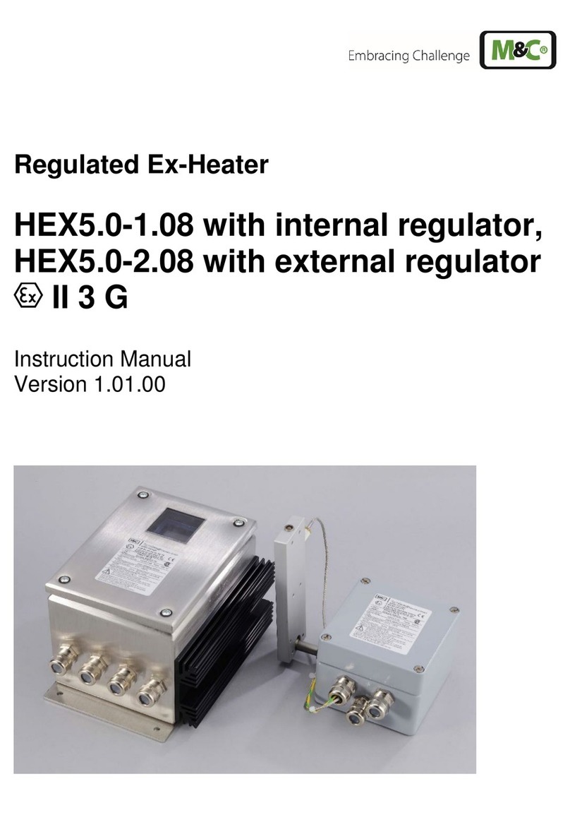
M&C HEX4-135 User manual

Self-regulating Ex-Heater
HEX4-135, HEX4-180
HEX4-SS-135, HEX4-SS-180
II 2 G II 2 D
Instruction Manual
Version 1.04.02

2 HEX4 | 1.04.02 www.mc-techgroup.com
List of Contents
1Declaration of conformity ............................................................................................................................3
2Safety instructions: Description of intended use .....................................................................................4
3Information for use in hazardous areas.....................................................................................................5
4Warranty..........................................................................................................................................................5
5Used terms and signals.................................................................................................................................5
6Application .....................................................................................................................................................7
7Description .....................................................................................................................................................7
8Technical data ................................................................................................................................................8
9Receipt of marchandise and storage..........................................................................................................9
10 Preparation for installation..........................................................................................................................9
11 Mounting ..................................................................................................................................................... 11
12 Electrical connection.................................................................................................................................. 11
13 Start-up......................................................................................................................................................... 13
14 Maintenance................................................................................................................................................ 14
14.1 Cleaning.......................................................................................................................................................................................................14
15 Appendix...................................................................................................................................................... 14
List of Illustrations
Figure 1 Terminal box HEX4 135/180.................................................................................................................................................12
This Operating Manual does not claim to be complete and is subject to technical modifications.
©09/2021 M&C TechGroup Germany GmbH. Reproduction of this document or ist content is not allowed without permission from M&C.
Version: 1.04.02

www.mc-techgroup.com HEX4 | 1.04.02 3
1DECLARATION OF CONFORMITY
CE - Certification
The product described in this operating manual complies with the following EU directives:
ATEX-Directive
The product described in this manual is produced in accordance with the EU directive for devices and protec-
tion systems for appropriate use in hazardous areas 2014/34/EU appendix II.
RoHS Directive
The requirements of the RoHS2 (‘Restriction of Hazardous Substances 2’) directive 2011/65/EU and its annexes
are met.
EMC-Instruction
The requirements of the EU directive 2014/30/EU “Electromagnetic compatibility“ are met.
Low Voltage Directive
The requirement of the EU directive 2014/35/EU “Low Voltage Directive“ are met.
The compliance with this EU directive has been examined according to DIN EN 61010.
Declaration of conformity
The EU Declaration of conformity can be downloaded from the M&Chomepage or directly requested from
M&C.
Manufacturer : M&C TechGroup Germany GmbH
Rehhecke 79
40885 Ratingen – Germany
Tel.: 02102/935-0
E-Mail: info@mc-techgroup.com
www.mc-techgroup.com

4 HEX4 | 1.04.02 www.mc-techgroup.com
2SAFETY INSTRUCTIONS: DESCRIPTION OF INTENDED USE
Observe the following basic safety precautions when using the instrument:
Warning
•Read the operating instructions before commissioning and using the device! The in-
structions and warnings given in the operating instructions must be followed.
•The Certificate of Conformity (see Appendix) must absolutely be observed.
•Work on electrical equipment is only to be carried out by qualified personnel
as per
the regulations currently in force.
•Attention must be paid to the requirements of VDE 0100 when installing high-power
electrical units with nominal voltages of up to 1000V as well as to the associated stand-
ards and stipulations.
•For use in hazardous areas, the relevant national and international standards and reg-
ulations must be heeded.
•When connecting the equipment, attention must be paid to the correct supply volt-
age according to the indications on the type plate.
•Protection against touching dangerously high electrical voltages:
Before opening the equipment, it must be switched off and hold no voltages. This also
applies to any external control circuits that are connected.
•The equipment is only to be used within the permitted range of temperatures.
•Check that the location is weather-protected. It should not be subject to either direct
rain or moisture.
•A residual current protective device (RCD) with a rated value of the fault current of not
more than 100 mA must be used.
•The heating radiator must be covered by a metal protection cover.
•Installation, maintenance, control and eventual repairs may only be done by author-
ized personnel with respect to the relevant stipulations.
•For installation in zone 21:
To prevent electrostatic discharge due to operational processes, for example by con-
tacting flowing media, the device has to be installed in an area
protected from any kind of flowing media.

www.mc-techgroup.com HEX4 | 1.04.02 5
3INFORMATION FOR USE IN HAZARDOUS AREAS
The identification of both variants is as follows:
II 2 G Ex eb mb IIC T4/T3 Gb
II 2 D Ex tb IIIC 135°C / 180°C
A certification has been executed by EXAM BBG Prüf- und Zertifizier GmbH.
Detailed information and a copy of the EG Type Examination Certificate und IECEx Certificate
of conformity are attached as appendix to this operating manual. Installation and operation
must be carried out in accordance with the conditions and installation instructions specified
in the Ex certificate (see appendix). Only then, a safe operation and function in hazardous
areas is guaranteed.
All changes of the standard configuration with parts which are not specified or approved by
M&C as well as repair and service works with not specified parts means a loss of the Ex-Cer-
tificate.
- In case of any doubt, please contact
M&C
directly or your
M&C
representative.
4WARRANTY
In case of a device failure, please contact immediately M&C or your M&C authorized distributor.
We have a warranty period of 12 months from the delivery date. The warranty covers only appropriately used
products and does not cover the consumable parts. Please find the complete warranty conditions in our terms
and conditions.
The warranty includes a free-of-charge repair in our production facility or the free replacement of the device. If
you return a device to M&C, please be sure that it is properly packaged and shipped with protective packaging.
The repaired or replaced device will be shipped free of delivery charges to the point of use.
5USED TERMS AND SIGNALS
Danger
The ‘Danger’ warning sign indicates that death, serious injury and/or signifi-
cant material damage will be the consequence, if the appropriate precau-
tions should not be taken.
Warning
The ‘Warning’ warning sign indicates that death, serious injury or damage to
property may occur if the relevant precautionary measures are not observed.
Caution
The ’Caution’ warning sign indicates that slight personal injury can occur if
the appropriate safety precautions are not observed.

6 HEX4 | 1.04.02 www.mc-techgroup.com
Caution
’Caution‘ indicates that damage to property can occur if the appropriate
safety precautions are not observed.
Attention
‘Attention’ indicates that an unintended result or situation can occur if the
corresponding information is not taken into account.
‘Ex‘ indicates important information about the product or about the corre-
sponding parts in the instruction manual, relating to usage in potentially ex-
plosive atmospheres.
Qualified personnel
‘Qualified personnel’ are experts who are familiar with the installation, com-
missioning, maintenance and operation of these types of products. The fol-
lowing knowledge is at least required for the work:
•Instructed person in EX-protection
•Trained person in the electrotechnical field
•Detailed knowledge of the manual and the applicable safety regulations
High voltages!
Protect yourself and others against damages which might be caused by high
voltages.
Hot surface!
Contact may cause burn! Do not touch!
Note
‘Note’ indicates important information relating to the product or highlights
parts of the documentation for special attention.
Wear protective gloves!
Working with chemicals, sharp objects or extremely high temperatures re-
quires wearing protective gloves.
Wear safety glasses!
Protect your eyes while working with chemicals or sharp objects. Wear safety
glasses to avoid getting something in your eyes.
Wear protective clothes!
Working with chemicals, sharp objects or extremely high temperatures re-
quires wearing protective clothes.

www.mc-techgroup.com HEX4 | 1.04.02 7
6APPLICATION
The electrical heater HEX 4.. has been developed for the heating of metal bodies (eg. M&C Gas sample probe
SP3000/SP3100.., M&C Filter FT-H..).
The heater is suitable for the use in hazardous areas of zone 1 or 21 (combustible dusts or combustible gases)
II 2 GD
The indicated maximum surface temperatures are never exceeded even in case of faults according to category
1 which are very rare. This means that the heater HEX4.. can also be used for those applications where the
heating energy has an effect to areas of zone 0 or 20 through a dividing wall.
The mounting onto the object to be heated is executed by M&C.
The heating radiator must be covered with a metallic protection shield.
7DESCRIPTION
The probe heater type HEX4-.. is designed for two temperature areas. It has got a heating plate with two self-
regulating heating cartridges, and a terminal box.
Version
Operating temperature °C [°F]
at 0 to 60 °C [32 to 140 °F]
ambient temperature
Max.
surface temperature °C [°F]
HEX4-180
120 to 160 [248 to 320]
180 [356]
HEX4-135
90 to 120 [194 to 248]
135 [275]
Table 1 Temperature ranges of the probe heater HEX4-..
An alarm contact is available for monitoring the temperature at the probe (low temperature):
•Switch temperature for version HEX4-180 > 100 °C [212 °F]
•Switch temperature for version HEX4-135 > 60 °C [140 °F]

8 HEX4 | 1.04.02 www.mc-techgroup.com
8TECHNICAL DATA
Electrical Heater Type HEX4-..
Mains connection HEX4..
100-230 V 50/60 Hz 400 W
Rated current 5 A
at start-up
Electrical connection HEX4..,
Temperature status alarm HEX4.. and
Back purge RS
Terminals; max. 4 mm²,
3 x M20 screwed cable gland
Terminal range 7-12 mm
Identification of heating:
Electrical-Heater HEX4-180
Electrical-Heater HEX4-135
II 2 G Ex eb mb IIC T3 Gb II 2 D Ex tb IIIC 180°C Db
II 2 G Ex eb mb IIC T4 Gb II 2 D Ex tb IIIC 135°C Db
BVS 04 ATEX E 253
IECEx BVS 15.0060
The maximum surface temperatures indicated in the identification
are never exceeded even in case of faults according to category 1
which are very rare.
Operating temperature HEX4-180
Operating temperature HEX4-135
120 to 160 °C [248 to 320 °F] at ambient temperature 0 to 60 °C [32
to 140 °F]
90 to 120 °C [194 to 248 °F] at ambient temperature 0 to 60 °C [32 to
140 °F]
Ready for work HEX4..
after 2 h
Temperature status alarm
HEX4-180
Temperature status alarm
HEX4-135
> 100 °C [212 °F]
> 60 °C [140 °F]
Alarm contact capacity (Option)
HEX4..
250 V 1.5 A AC, 0.5 A DC
Ambient temperature
-20 to 60 °C [-4 to 140 °F],
SS-Version: -20 to 90 °C [-4 to 194 °F]
System of protection
IP66 (EN 60529)
Following standards have been used
IEC 60079-0: 2017 Ed.7 EN 60079-0:2018
IEC 60079-7: 2015 Ed.5 EN 60079-7:2015/A1 2018
IEC 60079-18: 2014 Ed.4 EN 60079-18:2015
IEC 60079-31: 2013 Ed.2 EN 60079-31:2014
Table 2 Technical Data HEX4..

www.mc-techgroup.com HEX4 | 1.04.02 9
9RECEIPT OF MARCHANDISE AND STORAGE
•Inspect the instrument for any damages during transport and, if necessary, inform your shipping insur-
ance immediately of the damage found.
Note
The instrument should be stored in a weatherproof frost-free area!
10 PREPARATION FOR INSTALLATION
Warning
First of all, make sure that the local conditions correspond to the indications on
the type plate.
•It must be assured that the limit temperature of the combustible dusts ac-
cording to table 3 is above the maximum surface temperature of all used
electrical
equipment respectively that the temperature class corresponds
to the inflammation temperature of the combustible gases/vapours, be-
cause it cannot be excluded that there could be some dust deposits.
Warning
For installation in zone 21:
To prevent electrostatic discharge due to operational processes, for example
by contacting flowing media, the device has to be installed in an area pro-
tected from any kind of flowing media.

10 HEX4 | 1.04.02 www.mc-techgroup.com
The actual operating parameters are to be checked according to the below table before the beginning of the
mounting.
Operating parameters for sampling station: ...................................................
Operating parameters for the combustible dust
Inflammation temperature of the dust
according EN50281-2-1 1999-08
...°C Procedure A
(layer)
....°C Procedure B
(cloud)
Limit temperature corre-
sponds to the lowest value out
of A–75 [°C] and
2/3 x B [°C]
..... (> max. surface temp. out of
table 8)
Conductive dust
Yes
No
Classification of areas process side
Classification of areas ambiance
Dust composition –
Lowest grain size > 2µm
µm
Dust load
g/m³
Operating parameters for the combustible gas
Gas composition
corrosive
toxic
explosive
Classification of areas process side
Classification of areas ambiance
Inflammation point of the gases or vapours
°C
(>max. surface temp. out
of table 8.1)
Corresponds to tem-
perature class
....................
Explosion group
IIA
IIB
IIC
Process conditions
Low pressure/ Overpressure situation
mbar
mbar
Process temperature
°C, min.
°C max.
Which parameters shall be measured, e.g. O
2
,
CO, SO
2
, NOX,..,
vol%
mg/Nm³
ppm
Required gas quantity
l/h, min.
l/h, max.
Required T90 time
Sec.
Table 3 Operating parameters

www.mc-techgroup.com HEX4 | 1.04.02 11
11 MOUNTING
Due to the fact that the heater HEX4.. is already mounted to the instrument to be heated, the operating in-
structions of the instrument to be heated must also be observed.
Warning
Works on the heater must only be carried out as far as the process and the ambience
have been declared to be a non-hazardous area, free of explosive atmosphere.
Warning
The instrument must be connected to earth. The leak resistance must be < 106
Ω
eve-
rywhere.
12 ELECTRICAL CONNECTION
Caution
Wrong power supply can destroy the instrument. When connecting the equipment,
please ensure that the supply voltage corresponds to the indication on the type plate.
Note
When setting power plants with nominal voltages of up to 1000 V, the requirements
of VDE 0100 and its relevant standards and regulations must be observed!
We recommend to use always temperature-resistant cables.
A main switch must be provided externally.
The electric supply circuit of the heater must be equipped with a slow 10 A fuse. The
electrical indications are to be seen in the technical data.
A residual current protective device (RCD) with a rated value of the fault current of not
more than 100 mA must be used.
We recommend using always the low temperature alarm contact in order to stop the
gas flow through the probe and thus to protect the downstream components in case
of alarm.

12 HEX4 | 1.04.02 www.mc-techgroup.com
The following figure shows the connection possibilities inside the terminal box of the heater
HEX 4 135/180....
Figure 1 Terminal box HEX4 135/180.....
The terminal box of the heater also contains the terminals for the backflushing valve of the gas sampling
probe SP3xxx (option RS).
•Remove the cover of the connecting box;
•Insert the mains cable for the heater (min. 3 x 1.5 mm2) through the screwed cable gland and connect
it to the respective terminals 1, 2, 3 (connecting plan inside the cover);
•Insert the signal cable for the temperature control through the cable entry and connect it to the re-
spective terminals 7, 8;
•For option back purge, connect the mains to terminal 4, 5 6;
•Screw the cover on again.

www.mc-techgroup.com HEX4 | 1.04.02 13
13 START-UP
Note
When setting power plants with nominal voltages of up to 1000 V, the requirements of
VDE 0100 as well as its relevant standards and regulations must be observed.
A main switch must be provided externally.
The electrical supply circuit must be equipped with a slow fuse of 10 A. The electrical
indications are in the technical data.
For option RS back purge:
The control circuit of the solenoid valve must be equipped with a slow fuse of 0.1 A.
A residual current protective device (RCD) with a rated value of the fault current of
not more than 100 mA must be used.
The radiator must be covered by a metal protective cover.
(Put on the weather protection cover of the probe.)
Before starting, check that the mains voltage is identical with the indication on the type plate.
Warning
The heated equipment must be mounted tightly. Make sure that there is a minimum
distance of 100 mm [approx. 3.9”] to other components in order to prevent an accumu-
lation of heat.
Switch on the mains supply.
Attention! In case of ambient temperatures higher than 40 °C [104 °F], the temperature
of the protective or isolation cover is higher than 60 °C [140 °F].
The total heating time is approx. 2 h. The signalling is carried out by the temperature status alarm.

14 HEX4 | 1.04.02 www.mc-techgroup.com
14 MAINTENANCE
For works during operation:
Hot surface temperatures!
Touching may lead to burns. Wear protective gloves.
Warning
When setting and executing any maintenance work on power plants with nominal
voltages of up to 1000 V, the requirements of VDE 0100 as well as its relevant standards
and regulations must be observed!
Any work on the heater must only be carried out as far as the ambience has been
declared to be a non-hazardous area, free from explosive atmospheres.
Before executing any maintenance work, the safety instructions relating to the installation and the process must
be followed.
Any recommendation regarding a maintenance cycle cannot be given. A useful maintenance cycle must be
determined in dependence on your specific process conditions.
14.1 CLEANING
The heater HEX4... should be checked in suitable time intervals. Dust layers of more than 5 mm [approx. 0.2”]
must be removed immediately.
Warning
To avoid static charges, always clean with a damp cloth.
15 APPENDIX
•EC-Type Examination Certificate
•IECEx Certificate of Conformity
Further product documentation can be seen in our internet catalogue under:
www.mc-techgroup.com

www.mc-techgroup.com HEX4 | 1.04.02 15

16 HEX4 | 1.04.02 www.mc-techgroup.com

www.mc-techgroup.com HEX4 | 1.04.02 17

18 HEX4 | 1.04.02 www.mc-techgroup.com

www.mc-techgroup.com HEX4 | 1.04.02 19

20 HEX4 | 1.04.02 www.mc-techgroup.com
This manual suits for next models
3
Table of contents
Other M&C Heater manuals
Popular Heater manuals by other brands

scandia
scandia 12240 Installation instructions & user manual

Webasto
Webasto Air Top 5000 ST manual

Dickinson
Dickinson Lofoten Operating and installation instruction manual

Jevi
Jevi 3000T Installation instruction

Trane
Trane UniTrane Installation operation & maintenance

Tulikivi
Tulikivi Tuisku Installation