M&C HEX5.0-1.08 User manual

Regulated Ex-Heater
HEX5.0-1.08 with internal regulator,
HEX5.0-2.08 with external regulator
II 3 G
Instruction Manual
Version 1.01.00

2 HEX5.0-1.08, HEX5.0-2.08 | 1.01.00 www.mc-techgroup.com
Dear customer,
Thank you for buying our product. In this instruction manual you will find all necessary information about
this M&C product. The information in the instruction manual is fast and easy to find, so you can start
using your M&C product right after you have read the manual.
If you have any question regarding the product or the application, please don’t hesitate to contact M&C
or your M&C authorized distributor. You will find all the addresses in the appendix of this manual.
For additional information about our products and our company, please go to M&C’s website www.mc-
techgroup.com. There you will find the data sheets and manuals of all our products in German and
English.
This Operating Manual does not claim completeness and may be subject
to technical modifications.
© 06/2016 M&C TechGroup Germany GmbH. Reproduction of this
document or its content is not allowed without permission from M&C.
Version: 1.01.00

www.mc-techgroup.com HEX5.0-1.08, HEX5.0-2.08 | 1.01.00 3
Table of Contents
1General information..................................................................................................................4
2Declaration of conformity.........................................................................................................4
3Safety instructions....................................................................................................................5
4Used terms and signal indications..........................................................................................6
5Information for use in hazardous areas ..................................................................................7
6Warranty....................................................................................................................................8
7Introduction...............................................................................................................................9
7.1 Serial numbers ................................................................................................................... 10
7.2 Power supply...................................................................................................................... 10
8Technical data.........................................................................................................................11
9Mounting..................................................................................................................................13
10 Electrical connection..............................................................................................................14
11 Starting-up...............................................................................................................................15
12 Closing down ..........................................................................................................................16
13 Maintenance............................................................................................................................16
14 Cleaning...................................................................................................................................17
15 Appendix .................................................................................................................................17
Table of Illustrations
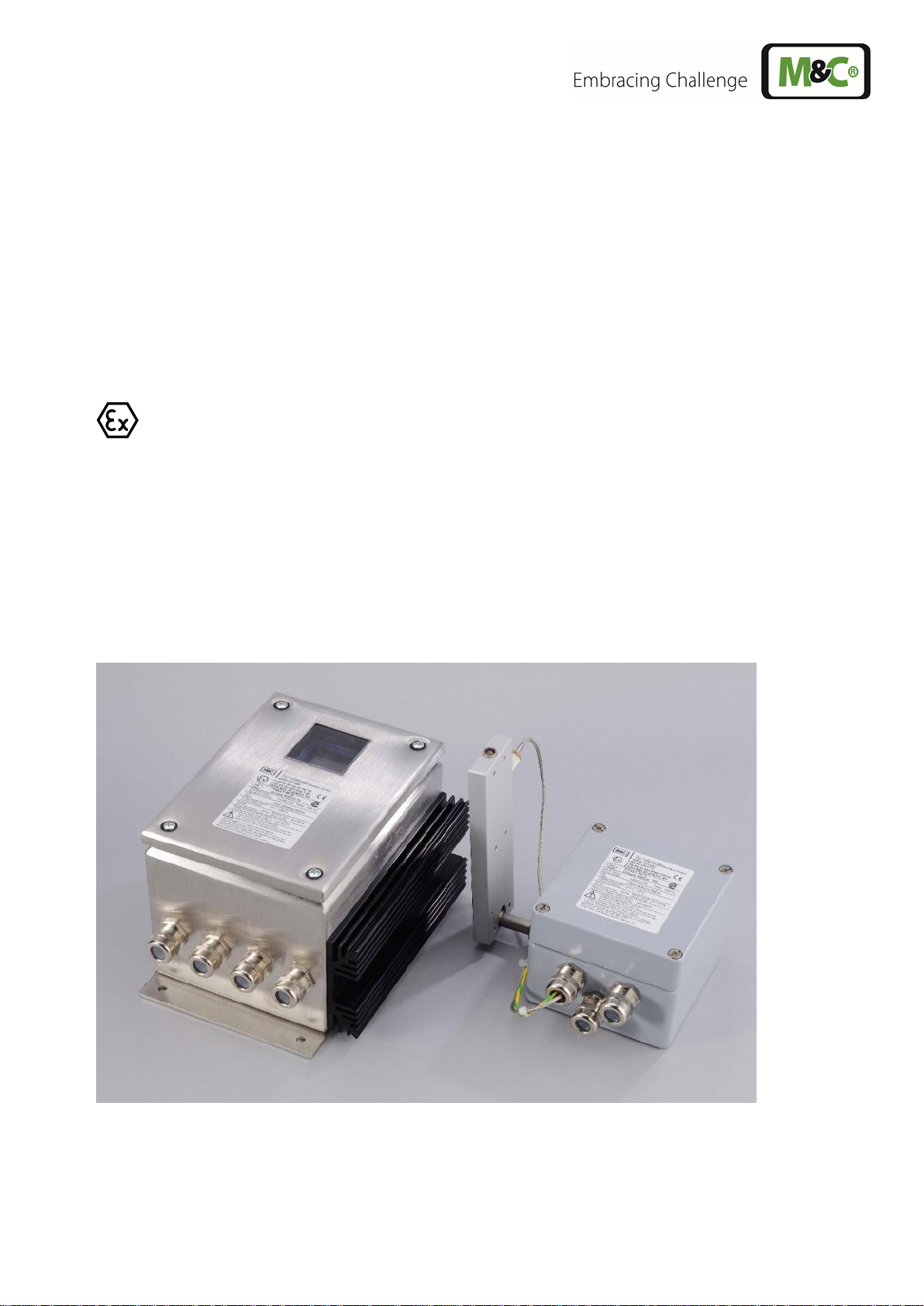
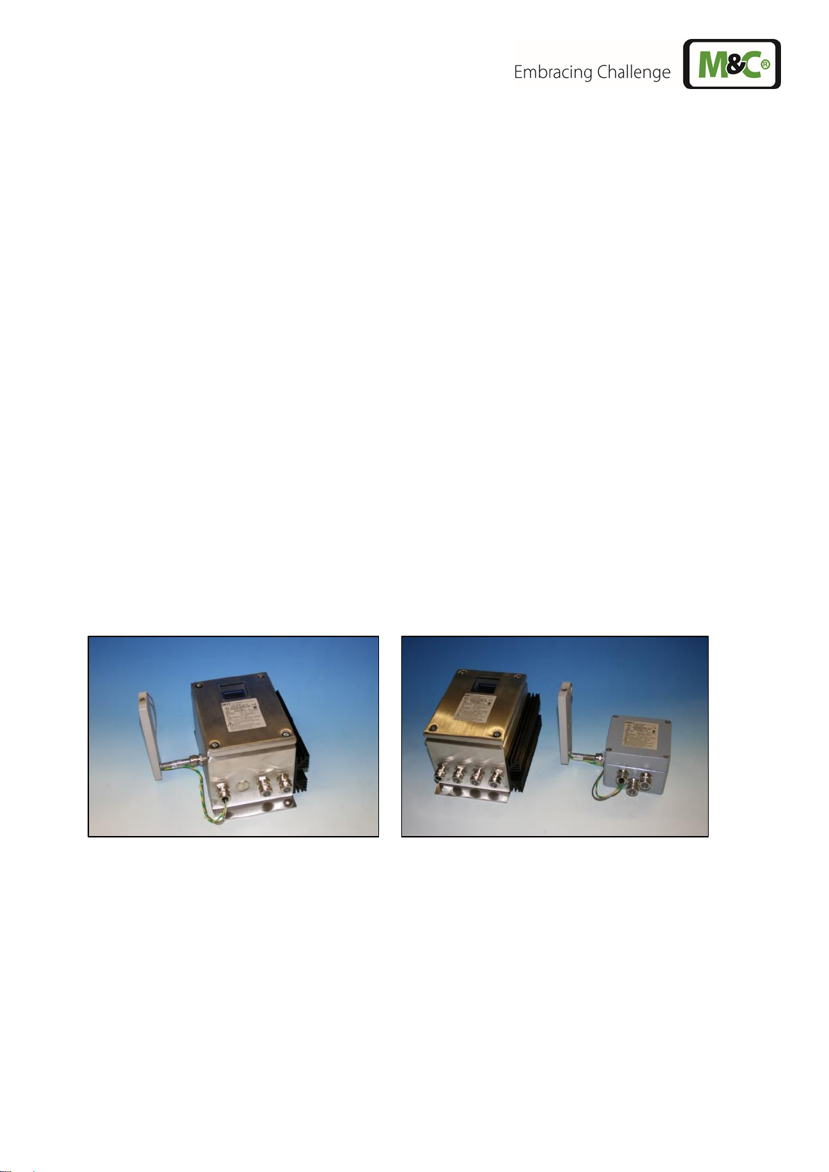
Figure 1 Version HEX 5.0-1.08 and Version HEX 5.0-2.08............................................................. 9
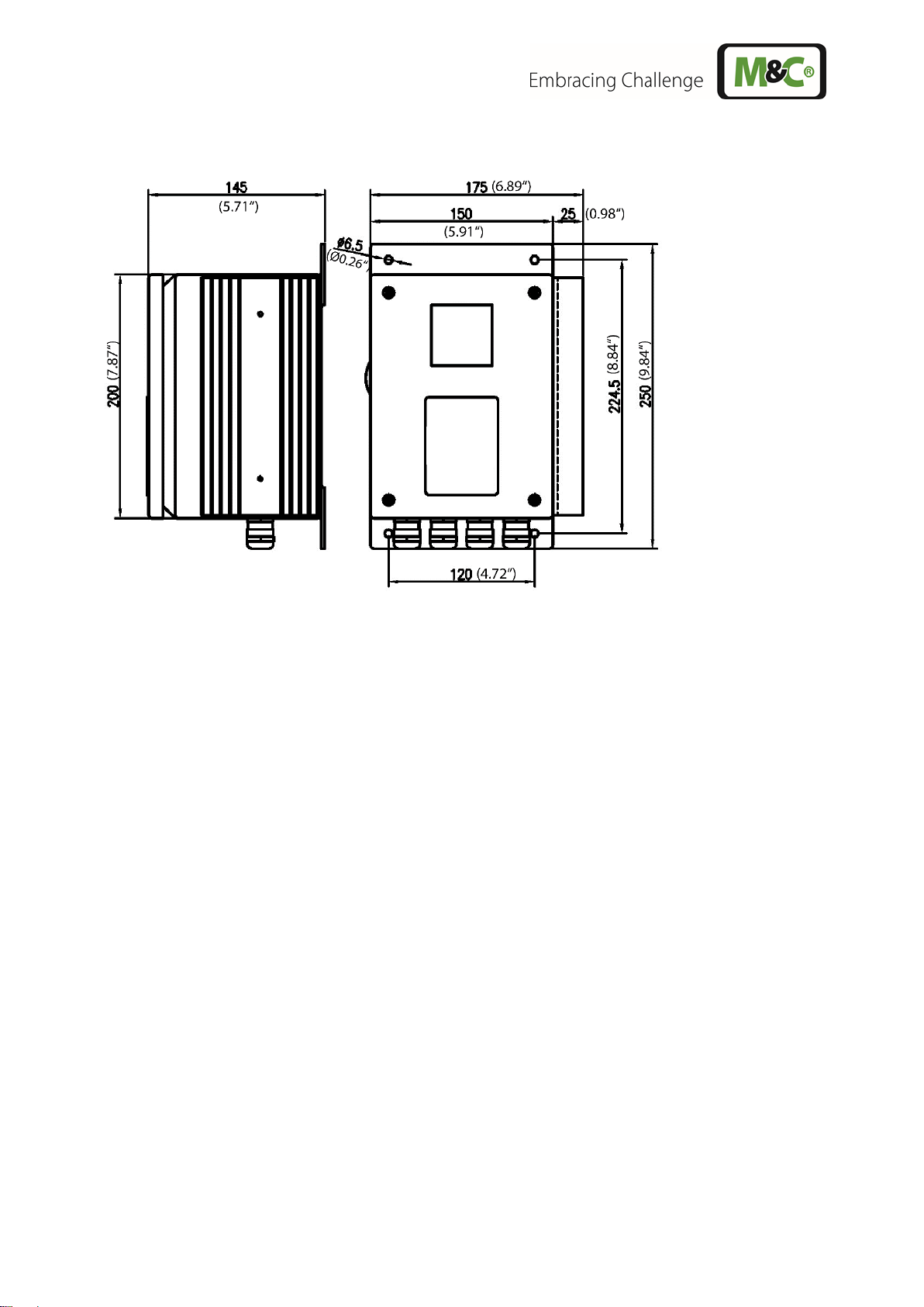
Figure 2 Dimensions of the temperature regulator HEX 5.0-2.08.................................................. 10
Figure 3 Electrical connection HEX 5.0-1.08................................................................................. 14
Figure 4 Electrical connection HEX 5.0-2.08................................................................................. 15
Figure 5 Example: Heater HEX5.0-1.08 mounted on gas sample probe SP3200.......................... 16
Figure 6 Circuit diagram HEX 5.0-1.08 ......................................................................................... 18
Figure 7 Circuit diagram HEX 5.0-2.08 ......................................................................................... 19
Figure 8 Option 2 x PT100: Connection diagrams HEX 5.0-1.08 and HEX 5.0-2.08 ..................... 20
Figure 9 Option 2 x PT100: Circuit diagram HEX 5.0-1.08............................................................ 21
Figure 10 Option 2 x PT100: Circuit diagram HEX 5.0-2.08............................................................ 22

4 HEX5.0-1.08, HEX5.0-2.08 | 1.01.00 www.mc-techgroup.com
Head Office
M&C TechGroup Germany GmbH Rehhecke 79 40885 Ratingen Germany
Telephone: 02102 / 935 - 0
Fax: 02102 / 935 - 111
E - mail: info@mc-techgroup.com
www.mc-techgroup.com
1 GENERAL INFORMATION
The product described in this manual has been built and tested in our production facility.
All M&C products are packed to be shipped safely. To ensure the safe operation and to maintain the
safe condition, all instructions and regulations stated in this manual need to be followed. This manual
includes all information regarding proper transportation, storage, installation, operation and
maintenance of this product by qualified personnel.
Please follow all instructions and warnings closely.
Please read this manual carefully before commissioning and operating the device. If you have any
questions regarding the product or the application, please don’t hesitate to contact M&C or your M&C
authorized distributor.
2 DECLARATION OF CONFORMITY
CE - Certification
The product described in this instruction manual complies with the following EU directives:
ATEX-Directive
The product described in this manual is produced in accordance with the directive for devices and
protection systems for appropriate use in hazardous areas 2014/34/EU appendix II.
EMV-Instruction
The requirements of the directive 2014/30/EU “Electromagnetic compatibility“ are met.
Low Voltage Directive
The requirement of the directive 2014/35/EU “Low Voltage Directive“ are met.
Declaration of conformity
The EU Declaration of conformity can be downloaded from the M&C homepage or directly requested
from M&C.

www.mc-techgroup.com HEX5.0-1.08, HEX5.0-2.08 | 1.01.00 5
3 SAFETY INSTRUCTIONS
Follow these safety directions and instructions regarding installation, commissioning and
operation of the device:
Read this manual before commissioning and operating the product. Make sure to follow all safety
instructions.
Pay attention to the Certificate of Conformity (see appendix).
Installation and commissioning of electrical devices must be carried out only by qualified skilled
personnel in compliance with the current regulations.
The installation and commissioning of the device must conform to the requirements of VDE 0100
(IEC 364) ‘Regulations on the Installation of Power Circuits with Nominal Voltages below 1000V’
and must be in compliance with all relevant regulations and standards.
For use in hazardous area, observe the relevant national and international instructions and
regulations.
Before connecting the device, make sure to compare the supply voltage with the specified
voltage on the product label.
Protection against touching dangerously high electrical voltages: Disconnect the power supply
before opening the device for access. The device must be switched off and voltage free. Make
sure that all extern power supplies are disconnected.
Operate the device only in the permitted temperature range. For details please refer to the
technical data sheet or manual.
Make sure that you install the device in a weather-protected location. The device should not be
exposed to either direct sun, rain or moisture.
Installation, maintenance, inspections and any repairs of the devices must be carried out only by
qualified skilled personnel in compliance with the current regulations.

6 HEX5.0-1.08, HEX5.0-2.08 | 1.01.00 www.mc-techgroup.com
4 USED TERMS AND SIGNAL INDICATIONS
DANGER!
This means that death, severe physical injuries and/or important
material damages will occur in case the respective safety measures
are not fulfilled.
WARNING!
This means that death, severe physical injuries and/or important
material damages may occur in case the respective safety measures
are not fulfilled.
CARE!
This means that minor physical injuries may occur in case the
respective safety measures are not fulfilled.
CARE!
Without the warning triangle meansthat a material damage may occur
in case the respective safety measures are not met.
ATTENTION!
This means that an unintentional situation or an unintentional status
may occur in case the respective note is not respected.
NOTE!
These are important information about the product or parts of the
operating manual which require user’s attention.
SKILLED STAFF
These are persons with necessary qualification who are familiar with
installation, use and maintenance of the product.
These are important information about the product or parts of the
instruction manual referring to operating in hazardous areas.

www.mc-techgroup.com HEX5.0-1.08, HEX5.0-2.08 | 1.01.00 7
5 INFORMATION FOR USE IN HAZARDOUS AREAS
The heater is suitable for use in hazardous areas Device 3.
Markings:
HEX 5.0-1.08 II 3 G Ex ec nC IIC temperature class T2 to T5 Gc
HEX 5.0-2.08 Controller II 3 G Ex ec nC IIC temperature class T2 to T5 Gc
HEX 5.0-2.08 Heater II 3 G Ex ec IIC temperature class T2 to T5 Gc
Detailed information and a copy of the Certificate are in the appendix of this instruction manual. Follow
closely all specified conditions and installation instructions stated in the Type Examination Certificate
regarding the installation and operation of the device. Only by complying to all requirements stated in
the Type Examination Certificate, safe operation in explosive atmospheres can be ensured.
Any modification of the standard configuration of the device with parts, which are not approved by M&C
and not explicitly specified for usage in explosive atmospheres, will void the Type Examination
Certificate. This also refers to any repair work and service using parts which are not M&C approved
and not specified for usage in explosive atmospheres.
Please don’t hesistate to contact M&C or your M&C distributer if you have any questions about parts,
repair work and services of the device.

8 HEX5.0-1.08, HEX5.0-2.08 | 1.01.00 www.mc-techgroup.com
6 WARRANTY
In case of a device failure, please contact immediately M&C or your M&C authorized distributor.
We have a warranty period of 12 months from the delivery date. The warranty covers only appropriately
used products and does not cover the consumable parts. Please find the complete warranty conditions
in our terms and conditions.
The warranty includes a free-of-charge repair in our production facility or the free replacement of the
device. If you return a device to M&C, please be sure that it is properly packaged and shipped with
protective packaging. The repaired or replaced device will be shipped free of delivery charges to the
point of use.

www.mc-techgroup.com HEX5.0-1.08, HEX5.0-2.08 | 1.01.00 9
7 INTRODUCTION
The electrical heater is designed to heat metal bodies (e.g. M&C sample gas probe SP.., M&C filter
FT-H..).
Only M&C personnel will mount the heater to the specified object.
The heater consists of an alumnium heating plate with a heating element (power consumption of up to
830 W), an electronical thermostat with limiter and a temperature sensor (PT100).
There are two versions available:
Type HEX 5.0-1.08 Heater with integrated temperature controller in a wall mount housing
Type HEX 5.0-2.08 Heater with terminal box in a wall mount housing and an external temperature
controller.
There is a warning label located on top of the heater.
The controller will be programmed according to the required temperature class by M&C personnel,
and the device will leave M&C protected against unauthorized access.
The temperature controller is equipped with an over temperature limiter which automatically shuts off
the heating, when the temperature is 5 °C (9 °F) higher than the adjusted set-point temperature. The
heater can be restarted either by interrupting the power supply or by pressing the ‘Exit’-button.
Indication on regulator K2 is in normal operating „AN“ (ON).
For temperature monitoring, the temperature controller is equipped with a low temperature alarm,
which sets off when the temperature is 10 °C (18 °F) lower than the set-point temperature. This status
alarm is available as a potential-free contact inside the terminal box. Indication on regulator K1 when
the operating temperature “AN” (ON) is reached. Indicator K3 shows that the heater is on.
Figure 1 Version HEX 5.0-1.08 and Version HEX 5.0-2.08

10 HEX5.0-1.08, HEX5.0-2.08 | 1.01.00 www.mc-techgroup.com
Figure 2 Dimensions of the temperature regulator HEX 5.0-2.08
7.1 SERIAL NUMBERS
The product label with the serial number is located on the top of the temperatur regulator.
Please refer to this serial number if you have any questions about your device or if you need to order
spare parts or consumables.
7.2 POWER SUPPLY
The probe can be operated on alternating current in the range of 240 V 50 / 60 Hz max. 800 W,
alternatively 120 V,50 / 60 Hz max. 830 W.
Product
label

www.mc-techgroup.com HEX5.0-1.08, HEX5.0-2.08 | 1.01.00 11
8 TECHNICAL DATA
Electrical Heater
Version HEX 5.0-1.08
VersionHEX 5.0-2.08
Temperature regulator
integrated
externally
Part No. 240 V Power
version
20 S 9651
20 S 9656
Part No. 120 V Power
version
20 S 965a
20 S 9656a
Option: connecting box for
heater out of stanles steel
20 S 9630
Power supply
240 V 50 / 60 Hz max. 800 W
or 120 V,50 / 60 Hz max. 830 W
Electr. Connection
Screwed cable gland
Range for cable glands 6 -12 mm (approx. 0.24”-0.47”),
Teminals; max. 4 mm²
System of protection
IP65 EN60529
Ex Protection
II 3 G Ex ec nC IIC temperature class T2 to T5 Gc
Temperature controller with
heater
II 3 G Ex ec nC IIC T2 –T5 Gc
Temperature controller
II 3 G Ex ec nC IIC T2 - T5 Gc
Heater with terminal box
II 3 G Ex ec IIC T2 –T5 Gc
temperature classes see next page
Ambient temperature
Temperature controller
0 °C to +55 °C
(32 °F to +131 °F)
Temperature controller
0 °C to +55 °C
(32 °F to +131 °F)
Heater terminal box
-20 °C to +70 °C
(~-4 to +158 °F)
Operating temperature
0 °C to max 230 °C (32 °F to max. 446 °F) depending on Temp.-class.
Please specify with order.
Temperature status alarm
10 °C (18 °F) lower than TSET Switch capacity 250 V 3 A AC, 0.25 A DC.
1 contact NO, potential-free.
Over temperature limiter
5 °C (9 °F) higher than TSET, manual Reset

12 HEX5.0-1.08, HEX5.0-2.08 | 1.01.00 www.mc-techgroup.com
Table temperature class
Atex Temperature class
Cenelec/IEC/Nec 505
Parameter for the
controller configuration
M&C
Part No
Atex
Atex
°C
Atex
Max °C
Atex -5°C
Limiter
°C
Operating temperature
°C
Status
°C
20 S 9608
T2
235
(455 °F)
230
(446 °F)
235 (455 °F)
230 (446 °F)
220 (428 °F)
20 S 9609
T2
220 (428 °F)
215 (419 °F)
205 (401 °F)
20 S 9610
T3
200
(392 °F)
195
(383 °F)
190 (374 °F)
185 (365 °F)
175 (347 °F)
20 S 9611
T3
180 (356 °F)
175 (347 °F)
165 (329 °F)
20 S 9612
T3
165 (329 °F)
160 (320 °F)
150 (302 °F)
20 S 9613
T3
155 (311 °F)
150 (302 °F)
140(284 °F)
20 S 9614
T3
140 (284 °F)
135 (275 °F)
125 (257 °F)
20 S 9615
T4
135
(275 °F)
130
(266 °F)
125 (257 °F)
120 (248 °F)
110 (230 °F)
20 S 9616
T4
100 (212 °F)
95 (203 °F)
85 (185 °F)
20 S 9617
T5
100
(212 °F)
95
(203 °F)
90 (194 °F)
85 (185 °F)
75(167 °F)
20 S 9618
T5
75 (167 °F)
70 (158 °F)
60 (140 °F)
Only for Version HEX5.0-2
20 S 9619
T6
75 (167 °F)
70 (158 °F)
60 (140 °F)
The programming and locking of the temperature regulator is made at works.

www.mc-techgroup.com HEX5.0-1.08, HEX5.0-2.08 | 1.01.00 13
9 MOUNTING
WARNING!
Make sure to mount the device in a weather-protected location.
The device should not be exposed to either sun, direct rain or any
other liquids.
The electrical heating HEX 5.0-1.08 will be already mounted completely with temperature controller on
the device by M&C personnel.
The temperature controller of the electrical heater HEX 5.0-2.08 will be delivered separately. This
temperature controller in its wall mount enclosure, needs to be mounted at the selected location and
then electrically connected to the terminal box of the heater. The mounting dimensions are shown in
figure 2.
•For the externally mounted temperature controller of the HEX 5.0-2.08, the maximum ambient
temperature of the heater connection box is +70°C (158 °F).
WARNING!
The heated part of the device must be tightly mounted. A minimum
distance of 100 mm (3.94”) to other components has to be kept in
order to avoid an accumulation of heat.

14 HEX5.0-1.08, HEX5.0-2.08 | 1.01.00 www.mc-techgroup.com
10 ELECTRICAL CONNECTION
CARE!
When connecting the equipment, make sure that the supply voltage
is identical with the information provided on the model type plate!
WARNING!
Only carry out work on the open device, when the area has been
proved to be „safe“.
NOTE!
The installation and commissioning of the device must conform to
the requirements of VDE 0100 (IEC 364) ‘Regulations on the
Installation of Power Circuits with Nominal Voltages below 1000 V’
and must be in compliance with all relevant regulations and
standards.
The cables used for connecting the heater must have a diameter of 6-12 mm (approx. 0.24” to
0.42”).
Depending on the ambient temperature at the mounting location, the cables used for the wiring
must be temperature resistant according to the requirements.
Connect the housing of the temperature controller, and if applicable the electrical connection
box of the HEX5.0-2.08, to earth (equipotential bonding).
Figure 3 Electrical connection HEX 5.0-1.08
Electrical connections electric heater HEX 5.0-1.08

www.mc-techgroup.com HEX5.0-1.08, HEX5.0-2.08 | 1.01.00 15
Figure 4 Electrical connection HEX 5.0-2.08
11 STARTING-UP
•Before connecting the device, make sure to compare the supply voltage with the specified
voltage on the product label.
•Before starting the device, check if the housing of the temperature controller and if applicable
the connection box (HEX 5.0-2.08) are connected to the equipotential bonding.
•Then close lid of the housing and switch on the power supply.
WARNING!
High surface temperatures!
Touching may result in burns.
When the ambient temperature is higher than 40°C (104 °F), the
temperature of the protection and isolating cover will be more than
60°C (140 °F).
Electrical connections electric heater HEX 5.0-2.08

16 HEX5.0-1.08, HEX5.0-2.08 | 1.01.00 www.mc-techgroup.com
Figure 5 Example: Heater HEX5.0-1.08 mounted on gas sample probe SP3200
The heater heats-up 1.5 °C per minute (2.7 °F per minute) by default via a programmed temperature
ramp. The total heating-up time is approx. 2 h for example for the gas sample probe SP3200 with
HEX5.0-1/2.08 regulated to 180 °C (356 °F). The temperature status alarm signals, when the heater
reaches the set temperature.
12 CLOSING DOWN
NOTE!
The ambient temperature at the device location needs to correspond
to the stated minimum and maximum ambient temperatures, even
when the unit has been switched off!
13 MAINTENANCE
WARNING!
Before carrying out any type of maintenance work, pay close attention
to the specific system and process safety measures!
DANGER!
Attention ! Explosion hazard!
Do not disconnect the device from the power supply when it is live!

www.mc-techgroup.com HEX5.0-1.08, HEX5.0-2.08 | 1.01.00 17
WARNING!
When working during operation:
High surface temperatures!
Touching may result in burns.
Wear protective gloves and assure that no unauthorized personnel
will touch the equipment!
WARNING!
Only carry out work on the open device, when the area has been
proved to be „safe“.
The installation and commissioning of the device must conform to the
requirements of VDE 0100 (IEC 364) ‘Regulations on the Installation
of Power Circuits with Nominal Voltages below 1000 V’ and must be
in compliance with all relevant regulations and standards.
Only change the fine-wire fuse F1 (1 AT 5x20) when the power supply
is disconnected.
DANGER!
Attention! The controller will be programmed according to the
required temperature class, and will leave M&C protected against
unauthorized access.
A wire strap on the terminal strip X1/5 protects against unauthorized
access.
The programming of the temperature class affects the complete
heater and can only be modified by M&C.
14 CLEANING
NOTE!
Clean the outside of the terminal box and the controller housing with
a damp cloth with a soap solution.
15 APPENDIX
Circuit diagrams
Connection and circuit diagrams option 2 x PT100
For additional manuals and data sheets, please have a look at our home page
www.mc-techgroup.com

18 HEX5.0-1.08, HEX5.0-2.08 | 1.01.00 www.mc-techgroup.com
Figure 6 Circuit diagram HEX 5.0-1.08
Values in brackets are for
controller 703
Keylock
Power N
Power PE
Power L

www.mc-techgroup.com HEX5.0-1.08, HEX5.0-2.08 | 1.01.00 19
Figure 7 Circuit diagram HEX 5.0-2.08
Power L
Power N
Power PE
Values in
brackets are
for controller
703
Keylock

20 HEX5.0-1.08, HEX5.0-2.08 | 1.01.00 www.mc-techgroup.com
Figure 8 Option 2 x PT100: Connection diagrams HEX 5.0-1.08 and HEX 5.0-2.08
Regler / Controller HEX5.0-1.08 2x PT100
Regler / Controller
HEX5.0-2.08
2x PT100
This manual suits for next models
5
Table of contents
Other M&C Heater manuals