FITTING THE INDUCT FAN
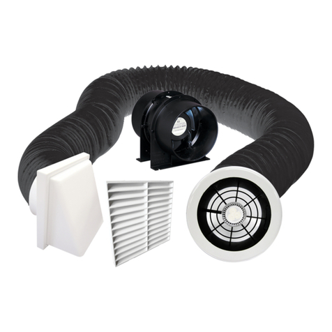
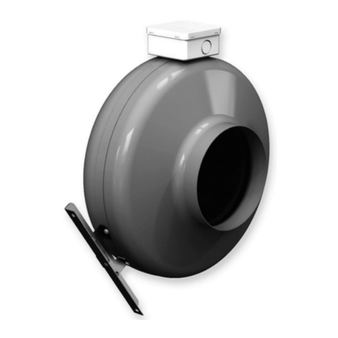
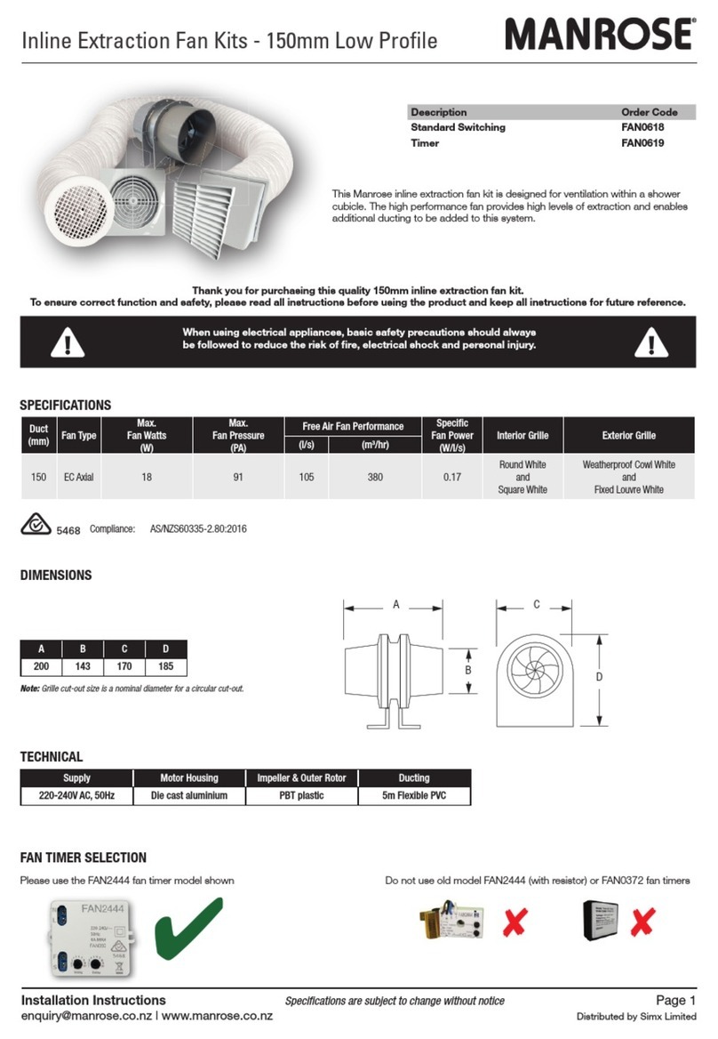
1. Select a suitable place for the axial fan to be screwed to a joist and secure using two screws through
the fixing bracket.
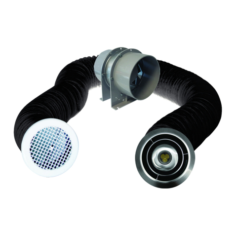
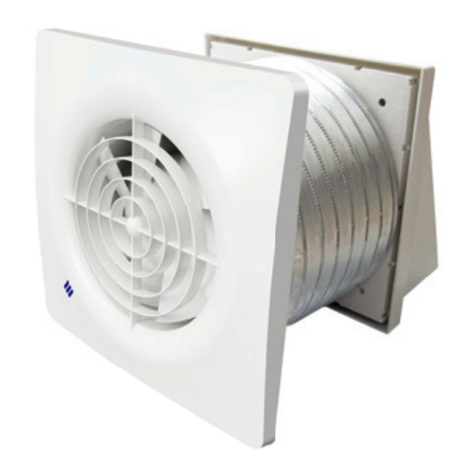
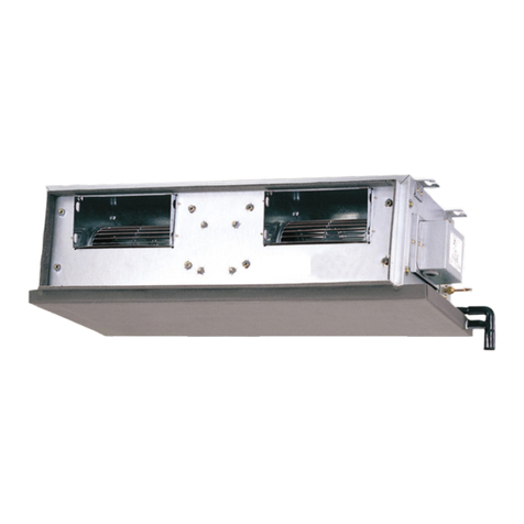
2. Select a suitable position either in the soffit or on an outside wall for the other grille, and cut a 130mm
hole. Attach one end of the flexible duct to the grille with the duct provided and from the outside feed
the ducting through the hole until the grille is flush with the soffit/wall. Secure the grille to the wall as
before. NB: It is best not to cut the flexible ducting until the grille has been screwed to the outside
surface to avoid the possibility of cutting the duct too short.
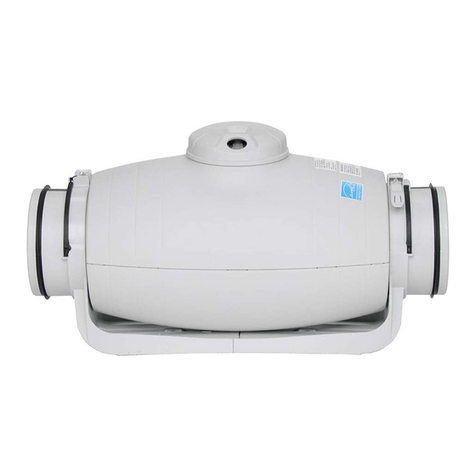
3. Pull the flexible ducting gently to the discharge spigot of the fan and cut it to length and connect to the
fan. NB: The discharge end of the fan unit is the end where you can see the fan blade clearly.
There is also an arrow on the unit showing the airflow direction.
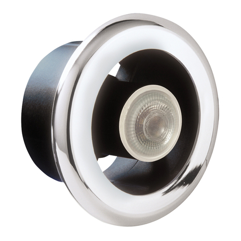
4. Connect the other piece of duct to the Extract-a-lite and onto the fan. Cut off and discard any excess
ducting. NB: Make sure wherever possible to keep the ducting running in a straight line as this will
improve the performance of the fan.
5. Remove the cover on the Fan Bracket and make the electrical connection as follows:
6. Wiring of Standard Model EL125S. Diagram 1 & 3
The fan can be connected to the light switch so that the fan will start when the light is switched on. The
fan should not be accessible to a person using either the shower or the bath.
NB: All wiring must be fixed securely and the cable to the fan should be a minimum of 1mm² in
section. All wiring must comply with current Regulations. This system should be installed by a qualified
electrician.
7. Wiring of Timer Model EL125T Diagram 2 & 4.
The fan can be connected to the light switch so that the fan will start when the light is switched on.
When switched off the fan and Extraxt-a-Lite will continue to run on for between 20 seconds
& 20 minutes (pre-set to 1 minute). The fan should not be accessible to a person using either the shower
or the bath.
NB: All wiring must be fixed securely and the cable to the fan should be a minimum of 1mm²in section.
All wiring must comply with current Regulations.
This system must be installed by a qualified electrician.
8. Timer Adjustment EL125T
This time delay can be adjusted by firstly switching off the power to the fan and removing the fascia.
Locate the rotary adjuster as shown in Diagram 4.
The serrated adjuster wheel can be rotated using a thumbnail to adjust the timer setting.
+ = Rotate to the left to increase the time (indicated by + on the diagram)
- = Rotate to the right to decrease the time (indicated by - on the diagram)
Only adjust with power switched off.
1 LIVE
2 NEUTRAL
Standard Model
Live
Neutral
230VAC
Switch Switched Live 12VAC
Extract-a-Lite
12VAC light
FAN
Existing
Light
230VAC
Existing Switch
12VAC
Permanent Live
DETAILED VIEW
Timer Model
3 PERMANENT LIVE
2 SWITCHED LIVE
1 NEUTRAL
3
2
1Neutral
Live
Recommended mounting
position for the timer model
Diagram 1 (EL125S) Standard Model This diagram is for a lighting circuit only
Diagram 2 (EL125T) Timer Model. This diagram is for a lighting circuit only
230/12V AC
SELV transformer
OR LED Driver
Extract-a-Lite
12VAC light
230/12V AC
SELV transformer
OR LED Driver
Diagram 3
Diagram 4
PLEASE NOTE:
These fans are double insulated
and therefore do not require an
earth. The time delay is preset for
approximately one minute and
can be adjusted as described.
