manuals.online logo
Brands
  1. Home
  2. •
  3. Brands
  4. •
  5. Manrose
  6. •
  7. Fan
  8. •
  9. Manrose CRA100HT&T User manual

Manrose CRA100HT&T User manual

INSTALLATION
INSTRUCTIONS
Switch off mains supply before making any electrical connections.
Installation must be supervised by a qualified electrician.
This appliance can be used by children aged from 8 years and above
and persons with reduced physical, sensory and mental capabilities
or lack of experience and knowledge if they have been given
supervision or instruction concerning the use of the appliance in a
safe way and understand the hazards involved.
Children shall not play with the appliance.
Cleaning and user maintenance shall not be made by children
without supervision.
Precautions must be taken to avoid the back-flow of gases into the
room from the open flue of gas or other open-fire appliances when
mounted in outside windows or walls.
Fan must be disconnected from electrical power before any
maintenance is carried out.
CRA100HT &T
Continuous Running Axial Fans
Wiring
1. Switch off mains supply before making electrical
connections. If in any doubt contact a qualified
electrician.
2. These units are for fixed wiring only. A flexible cord
must not be used. All wiring must be fixed securely
and the cable to the fan should be a minimum of
1mm2in section. All wiring must comply with current
I.E.E. Regulations or local regulations if outside the
UK.
3. A double pole fused spur having contact separation
of at least 3mm in all pole must be used and fitted
with a 3A fuse.
4. This fan is double insulated and does not require an
earth connection.
5. The fan should not be accessible to a person using
either the shower or the bath.
Location
1. When installing fan through an external wall, an
external wall grille must be fitted at all times.
2. For best results this Extractor Fan should be fitted
as high on the wall as possible, or if preferred, on
the ceiling. Note: Pullcord models should not be
installed in a ceiling.
3. Where ducted fans are used to handle moisture-
laden air, such as a bathroom, a condensation
trap should be fitted in any vertical exhaust ducts.
Horizontal ducts should be arranged to slope
slightly away from the fan. Ducts passing through
cold voids must be suitably insulated.
4. Do not install the unit within a shower cubicle
or anywhere else where there is a risk of being
sprayed with water (Please see our range of
showerfans for these installations.).
5. If the fan is installed in a room containing a fuel
burning appliance, the installer must ensure that
the air replacement is adequate for both the fan
and the fuel burning appliance.
IMPORTANT: READ THESE INSTRUCTIONS BEFORE COMMENCING THE INSTALLATION
DO NOT - install this product in areas where the following may be present or occur:
• Excessive oil or a grease laden atmosphere.
• Corrosive or flammable gases, liquids or vapours.
• Ambient temperatures higher than 40°C or less than –5°C.
• Possible obstructions which would hinder the access or removal of the Fan.
SAFETY AND GUIDANCE NOTES
1. When the Fan is used to remove air from a room containing a fuel-burning appliance, ensure that the air
replacement is adequate for both the fan and the fuel-burning appliance.
2. The Fan should not be used where it is liable to be subject to direct water spray for prolonged periods of time.
3. Where ducted Fans are used to handle moisture-laden air, such as a bathroom, a condensation trap should
be fitted in any vertical exhaust ducts. Horizontal ducts should be arranged to slope slightly downwards away
from the Fan. Ducts passing through cold voids must be suitably insulated.
4. This product should not be disposed of with household waste. Please recycle where facilities exist. Check
with your local authority for recycling advice.
A. INSTALLATION
PANEL/CEILING MOUNTING
1. For panel/ceiling mounting the fan should be installed into a closed duct system of at least 1.2m long or
protected by an exterior air grille that must comply with the standard requirements of your country to prevent
access to the fans impeller.
2. Cut a 105mm diameter hole.
3. Loosen the screw at the bottom of the grille and remove the front grille. Mark the screw centres through the
holes in the fan back plate. Drill, plug and screw into position.
4. Attach ducting as required for the installation.
5. Wire the fan as described in the Wiring section.
6. After installation, ensure impeller rotates freely.
7. Replace the grille and tighten the retaining screw.
WALL MOUNTING
1. For wall mounting cut a 115mm diameter hole through the wall and insert the wall sleeve. Slope the sleeve
slightly downwards away from the fan. Cut to length and cement both ends into position flush with the wall
faces.
2. Loosen the screw in the bottom of the grille and remove the front grille. Mark the screw centres through the
holes in the fan back plate. Drill, plug and screw into position.
3. Fix exterior grille into position with the louvres positioned downwards. (Note:- The grille must comply with the
standard requirements of your country to prevent access to the fans impeller).
4. Wire the fan as described in Section B-Wiring. Adjust any settings as required (see Section C-Setup).
5. After installation, ensure impeller rotates freely.
6. Replace the grille and tighten the retaining screw.
B. WIRING.
WARNING: THE FAN AND ANCILLARY CONTROL EQUIPMENT MUST BE ISOLATED FROM THE
POWER SUPPLY DURING THE INSTALLATION / OR MAINTENANCE.
• The cross - sectional area of supply cord used should be ranged from 1 - 1.5mm2.
• Cable entry can only be made from the rear of the fan.
• The extraction fan is suitable for connection to 220-240V 50Hz supply.
• The fan is a class II double insulated product and MUST NOT be earthed.
1. Select and follow the appropriate wiring diagram. (Fig. 1 or 2)
2. Check all connections have been made correctly and ensure all terminal connections and cable clamps are
securely fastened.
Fig.1 Continuous trickle (6 or 9L/s) with no remote boost facility or Continuous Boost (15 L/s) with no trickle
facility.
Fig.2 Continuous trickle (6 or 9 L/s) with boost facility (15L/s) via remote switch.
SL
N
L
SL
N
L
SWITCHED SPUR
FAN
MAINS
220-240VAC
Two Wire systems
Three Wire Systems
SL
N
L
N
~
L
SWITCHED SPURFAN
MAINS
220-240VAC
1. Loosen screw.
2. Pull grille
slightly away
from bottom
edge.
3. Push grille upwards until
clear from the fan chassis.
C. SETUP
WARNING: THE FAN AND ANCILLARY CONTROL EQUIPMENT MUST BE ISOLATED FROM THE
POWER SUPPLY DURING THE INSTALLATION / OR MAINTENANCE
Accessing the wiring and control settings – (Fig. 3)
Trickle speed selection (6l/s or 9l/s) – Fig. 4
The fan can extract at 6l/s (22m3/h) or 9l/s (32m3/h) flow
rate.
The fan will boost to 15l/s (54m3/h) when the LS
connection is switched.
• Factory set at 6l/s (22m3/h).
• Remove jumper connector (JP1) if 9l/s (32m3/h)
extract flow rate is required.
Fig 4
DIP SWITCH
Timer adjustment
T models
OR
Humidity adjustment
HT models
JP1
JP2
PLEASE DISPOSE OF
USED FAN AT YOUR
LOCAL CIVIC AMENITY
SITE. DO NOT DISPOSE
IN DOMESTIC WASTE
077632 07/18
SERVICING AND MAINTENANCE.
WARNING: THE FAN AND ANCILLARY CONTROL EQUIPMENT MUST BE ISOLATED
FROM THE POWER SUPPLY DURING MAINTENANCE.
1. At intervals appropriate to the installation, the fan should be inspected and cleaned to ensure there is no build
up of dirt or other deposits.
2. Carefully push the front panel of the grille upwards away from the base part of the grille (Fig. 5).
Wipe the inlets and front face with a damp cloth until clean.
The fan has sealed for life bearings, which do not require lubrication.
Dip switch 1 should be in the ‘ON’ position for constant trickle mode or ‘OFF’ for use as an intermittent fan. In
this mode the fan will only run when the pullcord or LS is activated.
Boost Timer Setting
With jumper JP2 removed the fan will enter boost when the LS connection is switched. The fan can continue to
boost for 15 minutes after the LS connection is switched off. With jumper JP2 in place there will be no overrun
timer, when the LS connection is switched off the fan will leave boost.
1. Max speed: Dip switch 2 in the ‘OFF’ position.
2. 15 l/s speed: Dip switch 2 should be in the ‘ON’ position. (Factory set)
Boost Speed Selection (Fig. 5):
The fan has two boost speed settings for different installation requirements:

Other Manrose Fan manuals

Manrose PRO Series User manual

Manrose

Manrose PRO Series User manual

Manrose LED Series User manual

Manrose

Manrose LED Series User manual

Manrose PRO Series User manual

Manrose

Manrose PRO Series User manual

Manrose HYPER150 EC User manual

Manrose

Manrose HYPER150 EC User manual

Manrose FAN0618 User manual

Manrose

Manrose FAN0618 User manual

Manrose VIVO FAN7291 User manual

Manrose

Manrose VIVO FAN7291 User manual

Manrose LED Series User manual

Manrose

Manrose LED Series User manual

Manrose FAN0531 User manual

Manrose

Manrose FAN0531 User manual

Manrose FAN5371 User manual

Manrose

Manrose FAN5371 User manual

Manrose 100T Assembly instructions

Manrose

Manrose 100T Assembly instructions

Manrose Aria 250 Motor User manual

Manrose

Manrose Aria 250 Motor User manual

Manrose CQF100 User manual

Manrose

Manrose CQF100 User manual

Manrose FAN7191 User manual

Manrose

Manrose FAN7191 User manual

Manrose Classic Series User manual

Manrose

Manrose Classic Series User manual

Manrose EXTRACT-A-LITE Service manual

Manrose

Manrose EXTRACT-A-LITE Service manual

Manrose Quiet Fan Conceal X5 S Assembly instructions

Manrose

Manrose Quiet Fan Conceal X5 S Assembly instructions

Manrose MET Series Assembly instructions

Manrose

Manrose MET Series Assembly instructions

Manrose FAN2303 User manual

Manrose

Manrose FAN2303 User manual

Manrose LED Series Installation guide

Manrose

Manrose LED Series Installation guide

Manrose FAN7189 User manual

Manrose

Manrose FAN7189 User manual

Manrose LEDSLKTC Assembly instructions

Manrose

Manrose LEDSLKTC Assembly instructions

Manrose CRA100T User manual

Manrose

Manrose CRA100T User manual

Manrose CLASSIC XF150 User manual

Manrose

Manrose CLASSIC XF150 User manual

Manrose FAN0046 User manual

Manrose

Manrose FAN0046 User manual

Popular Fan manuals by other brands

Faro ALO installation guide

Faro

Faro ALO installation guide

Lasko 3130 instructions

Lasko

Lasko 3130 instructions

Ventair Brook 4 Important Installation Instruction and Warranty Instructions

Ventair

Ventair Brook 4 Important Installation Instruction and Warranty Instructions

Qilive Q.6872 user manual

Qilive

Qilive Q.6872 user manual

Vent-Axia T Series Installation & user's instructions

Vent-Axia

Vent-Axia T Series Installation & user's instructions

GE 20390 user manual

GE

GE 20390 user manual

Regency Cayman owner's manual

Regency

Regency Cayman owner's manual

Be Cool BC40SNST2202F manual

Be Cool

Be Cool BC40SNST2202F manual

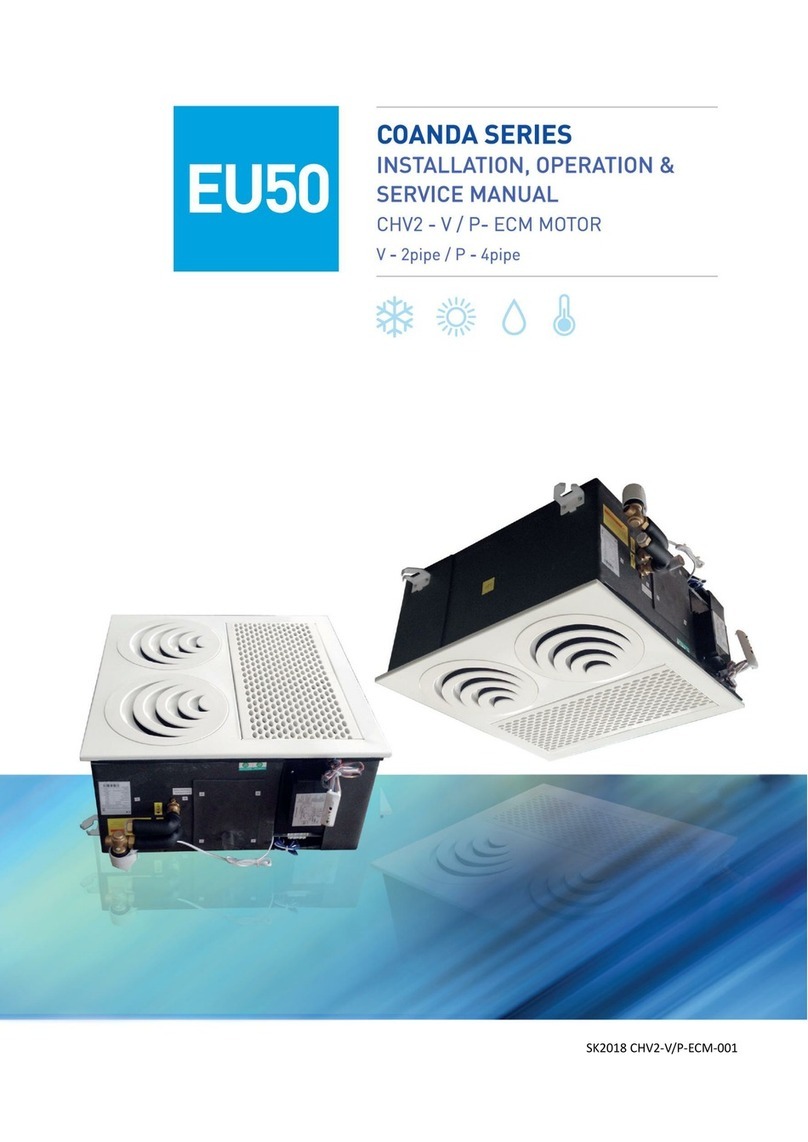
Polar Air Coanda Series Installation, operation and service manual

Polar Air

Polar Air Coanda Series Installation, operation and service manual

Orbegozo SF 3345 instruction manual

Orbegozo

Orbegozo SF 3345 instruction manual

Princess SMART 01.358450.02.001 instruction manual

Princess

Princess SMART 01.358450.02.001 instruction manual

Vortice A-E Instruction booklet

Vortice

Vortice A-E Instruction booklet

Exido 271-105 Specifications

Exido

Exido 271-105 Specifications

Hunter Sontera Owner's guide and installation manual

Hunter

Hunter Sontera Owner's guide and installation manual

aerauliqa AIRQURE-P1 Installation, use & maintenance manual

aerauliqa

aerauliqa AIRQURE-P1 Installation, use & maintenance manual

Savoy House Nomad 52-EOF-5W-WH owner's manual

Savoy House

Savoy House Nomad 52-EOF-5W-WH owner's manual

Salda AMBERAIR Assembly manual

Salda

Salda AMBERAIR Assembly manual

Vents VENTS TT Series user manual

Vents

Vents VENTS TT Series user manual

manuals.online logo
manuals.online logoBrands
  • About & Mission
  • Contact us
  • Privacy Policy
  • Terms and Conditions

Copyright 2025 Manuals.Online. All Rights Reserved.