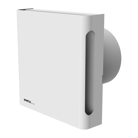
Manrose FAN2303 User manual


This manual suits for next models
4
Table of contents
Other Manrose Fan manuals
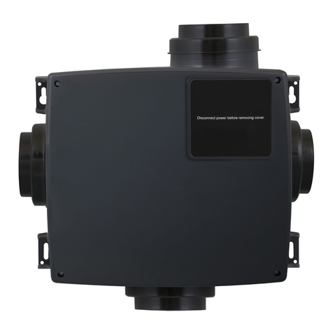
Manrose
Manrose MANI3000N Assembly instructions

Manrose
Manrose CQF100 User manual
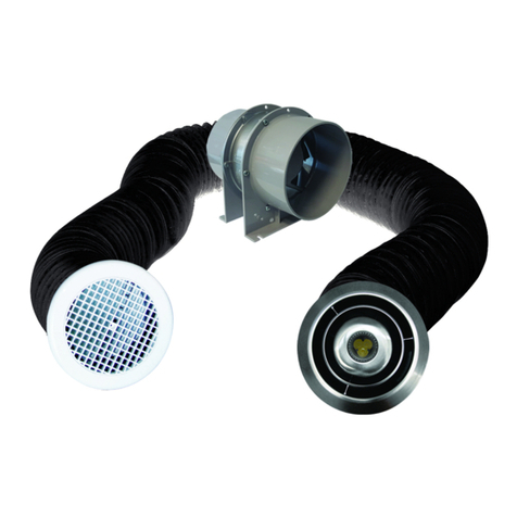
Manrose
Manrose LED Series User manual
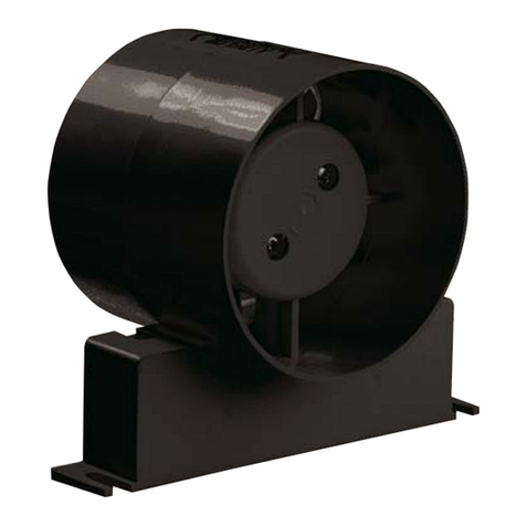
Manrose
Manrose FAN0090 User manual
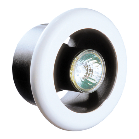
Manrose
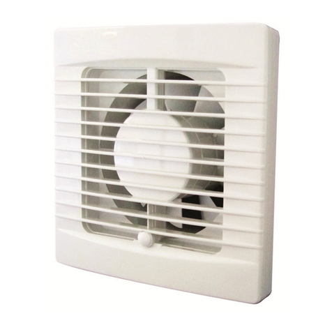
Manrose EXTRACT-A-LITE Service manual
Manrose
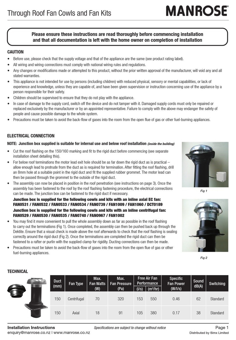
Manrose FAN0046 User manual
Manrose
Manrose FAN0531 User manual

Manrose
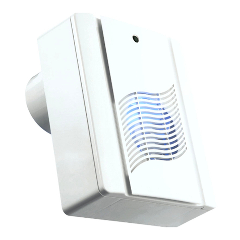
Manrose CLASSIC XF150 User manual
Manrose
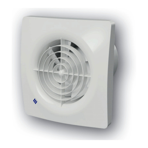
Manrose M200P User manual
Manrose
Manrose FAN7180 User manual

Manrose
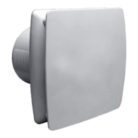
Manrose CRA100T User manual
Manrose
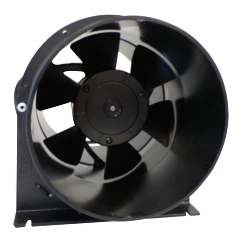
Manrose MRUF150WH Assembly instructions
Manrose
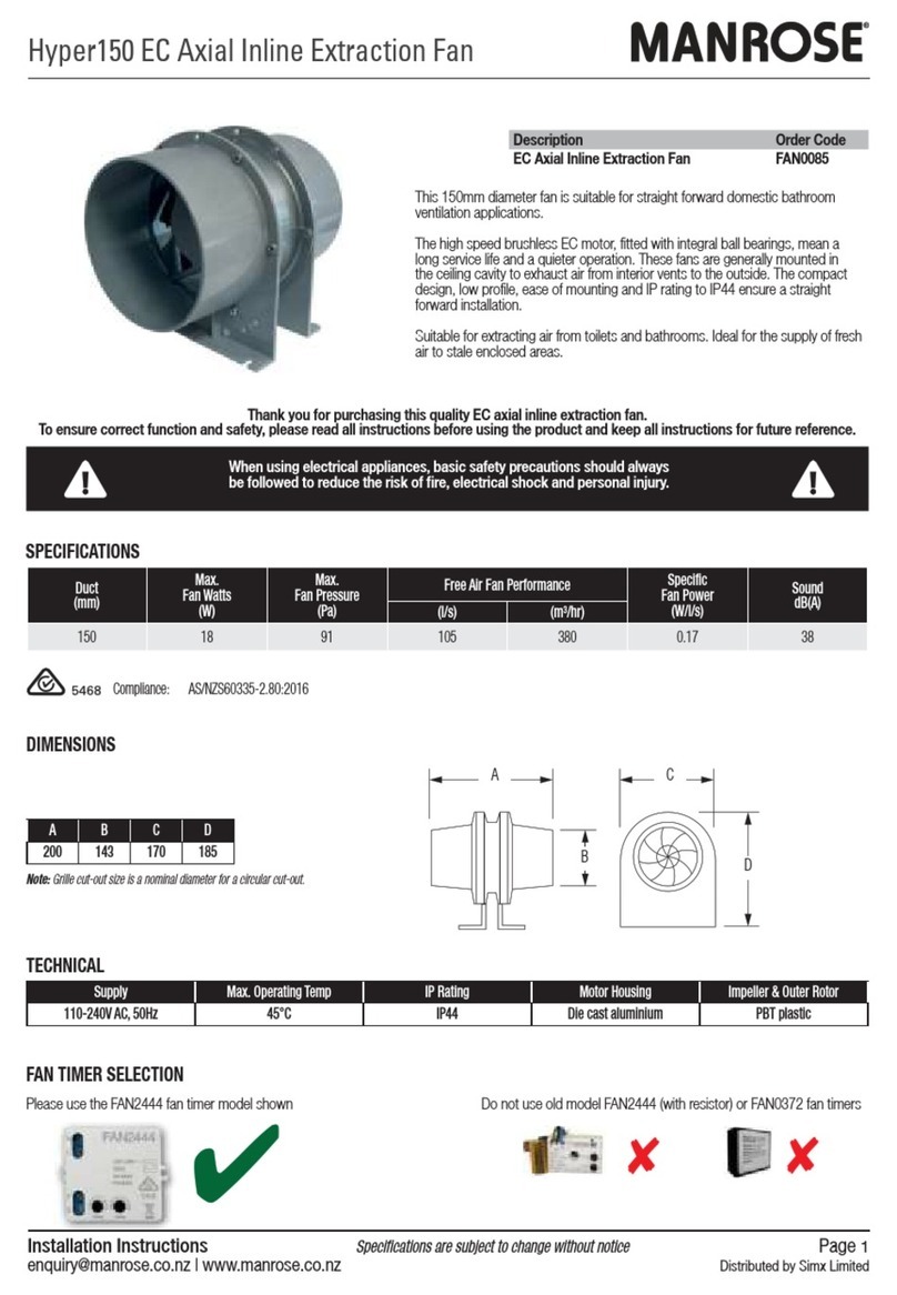
Manrose HYPER150 User manual
Manrose
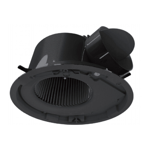
Manrose FAN0085 User manual
Manrose
Manrose LED Series User manual
Manrose
Manrose LED Series Installation guide
Manrose
Manrose FAN7189 User manual

Manrose
Manrose FAN5375 User manual
Manrose
Manrose MET Series Assembly instructions
Manrose
Manrose COMT Series User manual
Popular Fan manuals by other brands
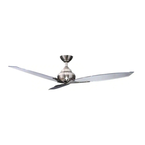
HAMPTON BAY
HAMPTON BAY Florentine manual
System air
System air KFB Operating and maintenance instructions
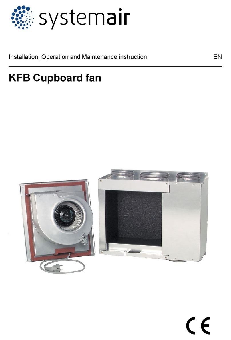
System air
System air KFB Installation,operation and maintenance instruction
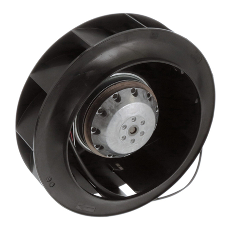
Ebmpapst
Ebmpapst R2E220-AA40-71 operating instructions
Ebmpapst
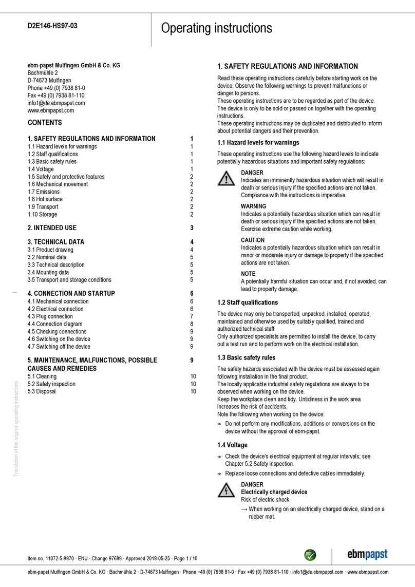
Ebmpapst D2E146-HS97-03 operating instructions
Ebmpapst
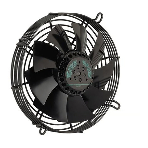
Ebmpapst S2D200-AH18-01 operating instructions

Air King
Air King 9102 Operating instructions and parts manual

HAMPTON BAY
HAMPTON BAY TY-50-L (HD) Use and care guide

M Confort
M Confort MF60 user manual
Ebmpapst
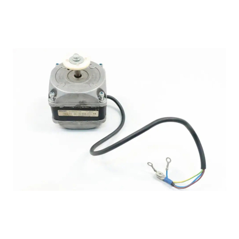
Ebmpapst M4Q045-BD03-04 operating instructions
Air King
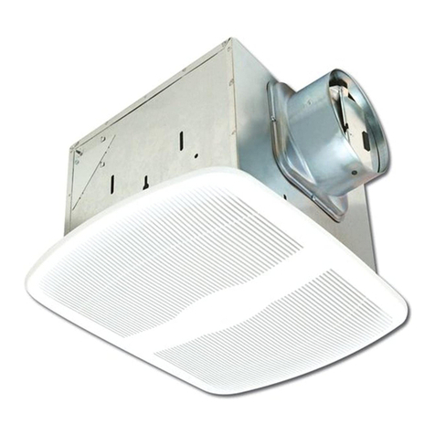
Air King AK150LS Series operating manual

Ebmpapst
Ebmpapst R3G310-AO52-01 operating instructions

Ebmpapst
Ebmpapst A3G710-AU21-01 operating instructions
CO/Tech
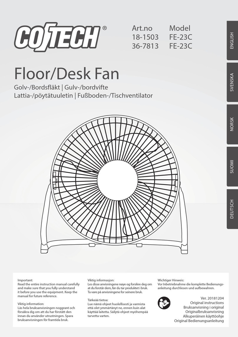
CO/Tech FE-23C Original instructions

Oriental motor
Oriental motor MU Series operating manual
Ebmpapst
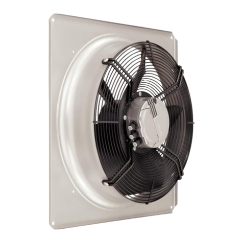
Ebmpapst W3G400-CC22-51 operating instructions

HAMPTON BAY
HAMPTON BAY VERANDA 499-493 owner's manual
Silvercrest
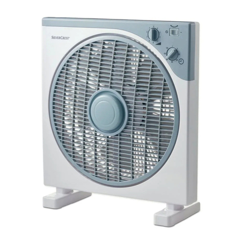
Silvercrest SBV 50 B1 Operation and safety notes
