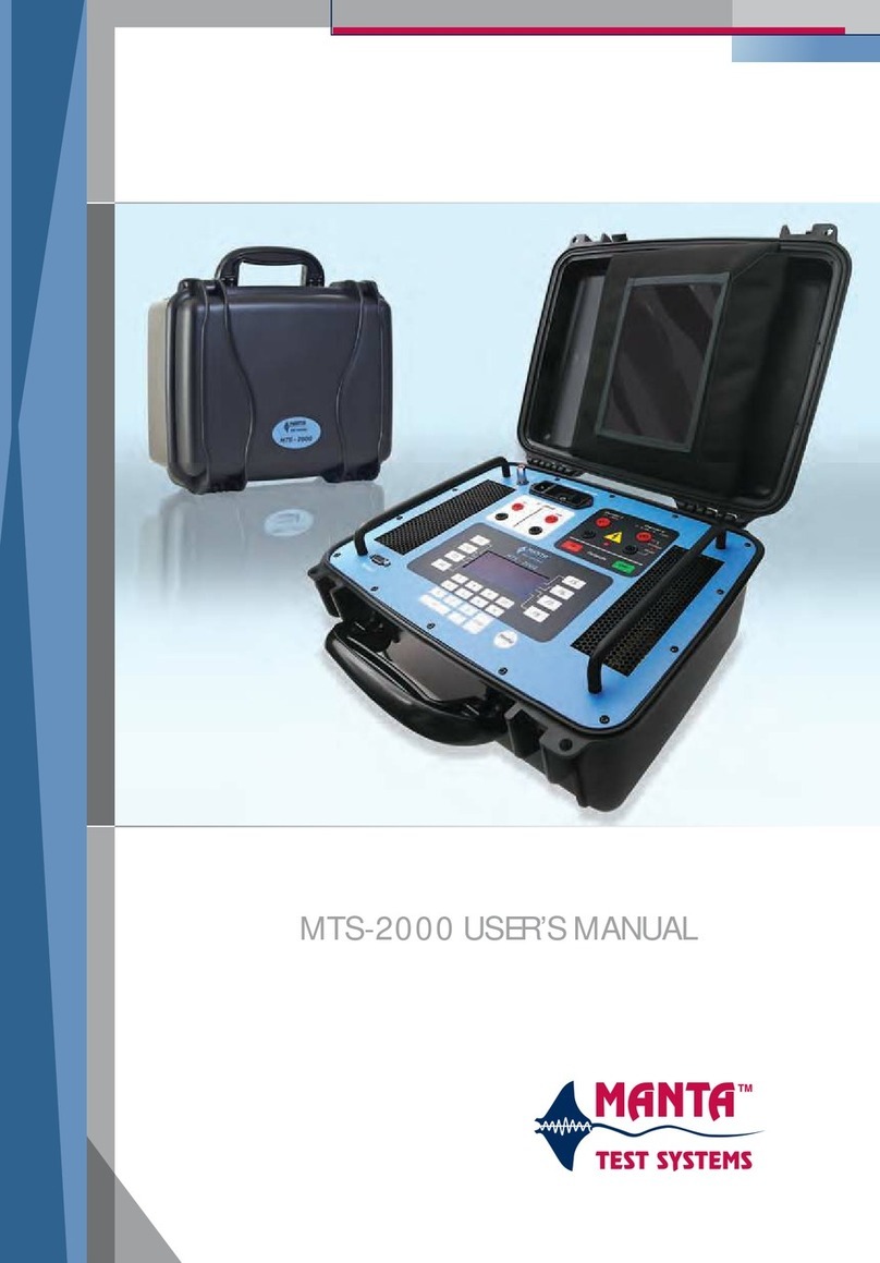
Manta MTS-3000 Series User manual

Manta Test Systems Incorporated
4060B Sladeview Crescent, Unit #1
Mississauga, Ontario, L5L 5Y5, Canada
Tel: +1(905) 828-6469 Fax: +1(905) 828-6850
e-mail: support@mantatest.com Internet: http://www.mantatest.com
MTS-3000 SERIES
MODULAR TEST SYSTEM
OPERATION AND REFERENCE MANUAL
First Edition
March 2001

MTS-3000 Modular Test System
Operation and Reference Manual
All rights reserved by Manta Test Systems Incorporated. No part of this publication may be reproduced or
distributed in any form or by any means without the permission of Manta Test Systems Incorporated.
The information and specifications contained within from Manta Test Systems are believed to be accurate
and reliable at the time of printing. However, because of the nature of this product, specifications shown in
this manual are subject to change without notice.
The features and capabilities described herein reflect those available in the following firmware versions:
• MTS-3000: 2.0
• MTS-3010: 1.1
• MTS-3020: 1.1
• MTS-3030: 2.0
• MTS-3040: 2.0
• MTS-3060: 2.0
March 2001.
Document ID#: CU M004 01A
Powertest™ is a trademark of Manta Test Systems Inc.
Manta Test Systems Incorporated
4060B Sladeview Crescent, Unit #1
Mississauga, Ontario, L5L 5Y5, Canada
Tel: +1(905) 828-6469 Fax: +1(905) 828-6850
Toll-free technical support (U.S.A & Canada): 1-800-233-8031

TABLE OF CONTENTS
MTS-3000 SERIES OPERATION ANDREFERENCE MANUAL iii
CU M004 01A 0$17$#7(67#6<67(06
TABLE OF CONTENTS
Section 1
Introduction
1.1 DISTINCTIVE CHARACTERISTICS.........................................................1-1
1.2 GENERAL DESCRIPTION..........................................................................1-1
1.3 APPLICATIONS...........................................................................................1-2
1.3.1 Standard Applications..............................................................................1-2
1.4 TERMINOLOGY .........................................................................................1-2
1.4.1 AC Current Module (ACI).......................................................................1-2
1.4.2 AC Voltage Module (ACV).....................................................................1-2
1.4.3 Control Module (CM)..............................................................................1-2
1.4.4 Device Under Test (DUT) .......................................................................1-2
1.4.5 Dynamic Fault Mode ...............................................................................1-2
1.4.6 Dynamic Relay Testing ...........................................................................1-3
1.4.7 MTS.........................................................................................................1-3
1.4.8 On Panel Testing......................................................................................1-3
1.4.9 Programming Mode.................................................................................1-3
1.4.10 Static Relay Testing.................................................................................1-3
1.4.11 Test Mode ................................................................................................1-3
1.4.12 V/I Module (VI).......................................................................................1-3
1.4.13 WFG Module...........................................................................................1-3
1.5 SAFETY CONSIDERATIONS.....................................................................1-3
1.6 TECHNICAL CONSIDERATIONS.............................................................1-4
1.7 TECHNICAL SUPPORT ..............................................................................1-4
Section 2
Specifications
2.1 INPUTS .........................................................................................................2-1
2.2 OUTPUTS .....................................................................................................2-1
2.2.1 MTS-3010 Digital I/O Module (Optional) ..............................................2-1
2.2.2 AC Currents: MTS-3060 AC Current Module ........................................2-1
2.2.3 AC Voltage and Current: MTS-3030 AC Voltage/Current Module........2-2
2.2.4 Output frequency .....................................................................................2-2
2.2.5 Harmonics................................................................................................2-1
2.2.6 Phase control............................................................................................2-2
2.2.7 DC Voltage: MTS-3020 DC Voltage Module.........................................2-2
2.2.8 DC Current: Current Source option.........................................................2-2
2.2.9 MTS-3010 Digital I/O Module (Optional) ..............................................2-2
2.3 METERING...................................................................................................2-3
2.3.1 Time measurement...................................................................................2-3
2.3.2 Frequency measurement ..........................................................................2-3
2.4 STATIC/DYNAMIC TESTING CAPABILITIES........................................2-3
2.5 OPTIONS.......................................................................................................2-3
2.5.1 System Options........................................................................................2-3
2.5.2 AC Voltage Module Options...................................................................2-3

TABLE OF CONTENTS
iv MTS-3000 SERIES OPERATION AND REFERENCE MANUAL
0$17$#7(67#6<67(06 CU M004 01A
2.5.3 AC Current Module Options....................................................................2-4
2.5.4 AC Voltage/Current Module Options......................................................2-4
2.6 PHYSICAL CHARACTERISTICS ..............................................................2-4
2.6.1 Minimum Configuration..........................................................................2-4
2.6.2 Control Module........................................................................................2-4
2.6.3 AC Voltage Module.................................................................................2-4
2.6.4 AC Current Module .................................................................................2-4
2.6.5 AC Voltage/Current Module ...................................................................2-4
2.6.6 Three Phase System: Control Module, AC Voltage and AC Current
Modules ...................................................................................................2-4
Section 3
Operation Summary
3.1 FRONT PANEL LAYOUT...........................................................................3-1
3.1.1 MTS-3000 Control Module, CM.............................................................3-1
3.1.2 MTS-3010 Digital I/O Module................................................................3-4
3.1.3 MTS-3010 DC Voltage Source................................................................3-5
3.1.4 MTS-3040 AC Voltage Module..............................................................3-5
3.2 REAR PANEL LAYOUT .............................................................................3-7
3.2.1 MTS-3000 Control Module Rear Panel...................................................3-7
3.3 BASIC APPLICATIONS ..............................................................................3-9
3.3.1 Getting Started.........................................................................................3-9
3.3.2 Basic AC Voltage, Current and Phase Angle Output ..............................3-12
3.3.3 Frequency Output ....................................................................................3-14
3.3.3.1 BASIC FREQUENCY OUTPUT. ...................................................3-14
3.3.3.2 ADVANCED FREQUENCY OUTPUT. .........................................3-15
3.3.4 DC Voltage ..............................................................................................3-15
3.3.4.1 BASIC DC VOLTAGE OUTPUT. .................................................3-15
3.3.4.2 ADVANCED DC VOLTAGE OUTPUT. .......................................3-16
3.3.5 DC Current Output...................................................................................3-16
3.3.6 High AC Voltage Output.........................................................................3-17
3.3.7 High AC Current Output..........................................................................3-18
3.3.8 Overcurrent Relay Test............................................................................3-18
3.3.8.1 SETUP. ............................................................................................3-19
3.3.8.2 MINIMUM PICKUP TEST. ............................................................3-19
3.3.8.3 INVERSE-TIME CHARACTERISTIC TEST. ...............................3-19
3.3.8.4 INSTANTANEOUS ELEMENT TEST. .........................................3-20
3.3.8.5 TARGET/SEAL-IN TEST. .............................................................3-21
3.3.9 Differential Relay - Three Terminal Type ..............................................3-22
3.3.9.1 PICKUP TEST. ................................................................................3-22
3.3.9.2 OPERATE TIME TEST. .................................................................3-23
3.3.9.3 HARMONIC RESTRAINT TEST. ................................................3-23
3.3.9.4 INSTANTANEOUS TEST. ............................................................3-24
3.3.9.5 TARGET TEST. .............................................................................3-24
3.3.10 Differential Relay - Independent Coil Type ............................................3-25
3.3.10.1 SLOPE TEST. ..................................................................................3-25

TABLE OF CONTENTS
MTS-3000 SERIES OPERATION AND REFERENCE MANUAL v
CU M004 01A 0$17$#7(67#6<67(06
3.3.10.2 OPERATE TIME TEST. .................................................................3-26
3.3.10.3 HARMONIC RESTRAINT TEST. .................................................3-27
3.3.10.4 INSTANTANEOUS TEST. .............................................................3-27
3.3.10.5 TARGET TEST. ..............................................................................3-28
3.3.11 Voltage Relay Test...................................................................................3-28
3.3.11.1 SETUP. ...........................................................................................3-28
3.3.11.2 MINIMUM PICKUP TEST. ...........................................................3-29
3.3.11.3 TIMING TEST. ..............................................................................3-29
3.3.11.4 TARGET/SEAL-IN TEST. .............................................................3-30
3.3.12 Frequency Relay Test ..............................................................................3-30
3.3.12.1 SETUP. ............................................................................................3-30
3.3.12.2 PICKUP TEST. ................................................................................3-30
3.3.12.3 TIMING TEST. ...............................................................................3-31
3.3.12.4 TARGET/SEAL-IN TEST. .............................................................3-31
3.3.12.5 UNDERVOLTAGE INHIBIT TEST. .............................................3-32
3.3.13 Synchronizing/Reclosing or Synchrocheck Relay...................................3-33
3.3.13.1 PHASE ANGLE LIMIT TEST. .......................................................3-33
3.3.13.2 VOLTAGE LIMIT TEST. ...............................................................3-33
3.3.13.3 SLIP FREQUENCY LIMIT TEST. .................................................3-34
3.3.14 Single Phase Impedance Relay or Directional Overcurrent Relay Test..3-35
3.3.14.1 SETUP. ............................................................................................3-35
3.3.14.2 REACH/MINIMUM PICKUP TEST. ..............................................3-35
3.3.14.3 MTA TEST. .....................................................................................3-36
3.3.14.4 OPERATE TIME TEST. .................................................................3-36
3.3.15 Three Phase Impedance Relay Test.........................................................3-37
3.3.15.1 PREPARATION. ............................................................................3-38
3.3.15.2 REACH TEST. ...............................................................................3-39
3.3.15.3 MTA TEST. .....................................................................................3-40
3.3.15.4 OPERATE TIME TEST. .................................................................3-40
3.3.16 Ground Fault Overvoltage Relay.............................................................3-41
3.3.16.1 SETUP. ...........................................................................................3-41
3.3.16.2 OVERVOLTAGE PICKUP TEST. ................................................3-42
3.3.16.3 OVERVOLTAGE TIMING TEST. ................................................3-42
3.3.16.4 UNDERVOLTAGE INHIBIT TEST. ............................................3-42
3.3.17 DC Auxilliary/Time-Delay Relay Test....................................................3-42
3.3.17.1 PICKUP TEST. ...............................................................................3-42
3.3.17.2 TIMING TEST. ..............................................................................3-43
Section 4
Detailed Operation
4.1 FAULT STATES...........................................................................................4-1
4.1.1 Prefault State............................................................................................4-1
4.1.2 Fault State ................................................................................................4-1
4.1.3 Postfault State ..........................................................................................4-1
4.2 CHARACTERISTICS OF FAULT STATES ...............................................4-1
4.3 OPERATION MODE - STATIC VS. DYNAMIC .......................................4-2

TABLE OF CONTENTS
vi MTS-3000 SERIES OPERATION AND REFERENCE MANUAL
0$17$#7(67#6<67(06 CU M004 01A
4.3.1 Static Fault Mode.....................................................................................4-2
4.3.2 Dynamic Fault Mode ...............................................................................4-3
4.4 TRIGGER/TIMER OPERATION.................................................................4-4
4.4.1 External Trigger Inputs............................................................................4-4
4.4.2 Trigger Threshold Levels.........................................................................4-4
4.4.3 Start Trigger (FLT)..................................................................................4-4
4.4.4 Stop Trigger (TRIP).................................................................................4-5
4.4.5 Reset.........................................................................................................4-5
4.4.6 Timer Start ...............................................................................................4-5
4.4.7 Two-Wire Pulse Timing ..........................................................................4-5
4.4.8 Timing in Cycles......................................................................................4-5
4.4.9 Testing SCR Output Type Relays............................................................4-5
4.5 CURRENT MODES......................................................................................4-6
4.5.1 Current Range..........................................................................................4-6
4.5.2 HARMONIC Current Mode ....................................................................4-7
4.5.2.1 DEFINITION OF PERCENTAGE HARMONIC. ..........................4-8
4.5.2.2 SPECIAL NOTES. ..........................................................................4-8
Section 5
Advanced Operation
5.1 MENU OPERATION....................................................................................5-1
5.1.1 Basic Usage..............................................................................................5-1
5.1.1.1 ACTIVATING THE MAIN MENU. ..............................................5-1
5.1.1.2 SELECTING MENU ITEMS. ........................................................5-1
5.1.1.3 MENU NAVIGATION. .................................................................5-1
5.2 SETTINGS.....................................................................................................5-5
5.2.1 Reset to Defaults......................................................................................5-5
5.2.2 Fault Type................................................................................................5-5
5.2.2.1 VECTOR MODE. ...........................................................................5-5
5.2.2.2 Φ−N,Φ−Φ, 3Φ MODE. ............................................................................5-5
5.2.3 Harmonics................................................................................................5-6
5.2.3.1 HARMONICS OPTIONS. ..............................................................5-6
5.2.4 Parallel Current........................................................................................5-6
5.2.5 Ramps ......................................................................................................5-7
5.2.5.1 FREQUENCY RAMPING. ............................................................5-8
5.2.5.2 PHASE RAMPING. .......................................................................5-8
5.2.5.3 VOLTAGE RAMPING. .................................................................5-8
5.2.5.4 CURRENT RAMPING. .................................................................5-8
5.2.6 Frequency 2..............................................................................................5-8
5.2.7 Breaker Times (Bkr Times)......................................................................5-9
5.2.8 AC Current Range (ACI Range)..............................................................5-9
5.2.9 Reclose.....................................................................................................5-9
5.2.10 Fault Incidence Angle (FIA)....................................................................5-10
5.2.11 Maximum Fault Duration (Max Flt Dur) ................................................5-10
5.2.12 Display Options .......................................................................................5-10
5.2.12.1 DEFAULT DISPLAY (Hz & Φ). ..................................................5-10

TABLE OF CONTENTS
MTS-3000 SERIES OPERATION AND REFERENCE MANUAL vii
CU M004 01A 0$17$#7(67#6<67(06
5.2.12.2 SLOPE. ...........................................................................................5-11
5.2.12.3 IMPEDANCE. ................................................................................5-11
5.2.12.4 FREQUENCY & V/Hz. ..................................................................5-13
5.2.12.5 FREQUENCY & SLIP. ..................................................................5-13
5.3 QUICK TEST ................................................................................................5-13
5.4 PREFERENCES............................................................................................5-15
5.4.1 Button Tone .............................................................................................5-15
5.4.2 VI Module #1...........................................................................................5-15
5.4.3 VI Module #2...........................................................................................5-15
5.4.4 COM 1 RS-232........................................................................................5-15
5.4.5 COM 2 RS-232........................................................................................5-15
5.4.6 Assign Ports.............................................................................................5-15
5.4.7 LCD Contrast...........................................................................................5-16
5.5 INDEX...........................................................................................................5-18
5.6 OTHER ..........................................................................................................5-18
5.6.1 Version.....................................................................................................5-18
5.6.2 Calibration ...............................................................................................5-18
5.6.3 Printer Test...............................................................................................5-18
5.6.4 Diagnostics...............................................................................................5-18
5.7 DIGITAL I/O.................................................................................................5-20
5.7.1 Input Channel 1 (I/P Chan 1) ..................................................................5-20
5.7.1.1 TRIP (ie STOP). ..............................................................................5-20
5.7.1.2 EXTERNAL START (FLT (ie STOP)). .........................................5-20
5.7.1.3 Pulse Timing. ..................................................................................5-20
5.7.1.4 Reset. ...............................................................................................5-20
5.7.1.5 Reclose. ...........................................................................................5-20
5.7.1.6 Foot Switch. ....................................................................................5-20
5.7.1.7 Off. ..................................................................................................5-21
5.7.2 Input Channel 2 (I/P Chan 2) ................................................................5-21
5.7.3 Input Debounce (I/P Debounce) .............................................................5-21
5.7.4 DC Current (IDC) ...................................................................................5-21
5.7.5 Output Channel 1 (O/P Chan 1) .............................................................5-21
5.7.5.1 FAULT (NO). ..................................................................................5-21
5.7.5.2 /FAULT (NC). .................................................................................5-21
5.7.5.3 Breaker Open (BKR OPEN: 52B). ..................................................5-21
5.7.5.4 PERMISSIVE. .................................................................................5-22
5.7.5.5 UNBLOCK. .....................................................................................5-22
5.7.5.6 Off. ..................................................................................................5-22
5.7.6 Output Delay (O/P Delay) ......................................................................5-22
5.7.7 Version.....................................................................................................5-22
Section 6
QuickTest
6.1 ADVANTAGES OF QUICKTEST...............................................................6-1
6.2 QUICKTEST ALGORITHMS......................................................................6-1

TABLE OF CONTENTS
viii MTS-3000 SERIES OPERATION AND REFERENCE MANUAL
0$17$#7(67#6<67(06 CU M004 01A
6.3 QUICKTEST TERMINOLOGY AND ABBREVIATIONS........................6-2
6.4 SUMMARY OF OPERATION.....................................................................6-2
6.5 TIMED 1Φ OVERCURRENT TEST ..............................................................6-4
6.5.1 Test Description.......................................................................................6-4
6.5.2 Example 1ΦTest Descriptions ................................................................6-4
6.6 INSTANTANEOUS 1Φ OVERCURRENT TEST ......................................6-6
6.6.1 Test Description.......................................................................................6-6
6.6.2 Example 1ΦInstantaneous Over Current (50).........................................6-6
6.7 TIMED 1ΦUNDER VOLTAGE TEST........................................................6-8
6.7.1 Test Description.......................................................................................6-8
6.7.2 Example 1ΦTimed Under Voltage (27)..................................................6-8
6.8 INSTANTANEOUS 1ΦUNDER VOLTAGE .............................................6-10
6.8.1 Test Description.......................................................................................6-10
6.8.2 Example 1ΦInstantaneous Under Voltage (27)......................................6-10
6.9 TIMED 1ΦOVER VOLTAGE TEST ..........................................................6-12
6.9.1 Test Description.......................................................................................6-12
6.9.2 Example 1ΦTimed Over Voltage (59)....................................................6-12
6.10 INSTANTANEOUS 1ΦOVER VOLTAGE TEST .....................................6-14
6.10.1 Test Description.......................................................................................6-14
6.10.2 Example 1ΦInstantaneous Over Voltage (59) ........................................6-14
6.11 TRANSFORMER DIFFERENTIAL TEST. ................................................6-16
6.11.1 Test Description.......................................................................................6-16
6.11.2 Example Transformer Differential...........................................................6-17
Section 7
RS-232C Interface
7.1 RS-232C CONNECTION..............................................................................7-1
7.1.1 Interface Specifications............................................................................7-1
7.1.2 COM 1 RS232C Port...............................................................................7-1
7.1.2.1 COM 1 RS-232C CONNECTOR PIN ASSIGNMENTS. ..............7-1
7.1.3 COM 2 RS232C Port...............................................................................7-2
7.1.3.1 COM 1 RS-232C CONNECTOR PIN ASSIGNMENTS. ..............7-2
7.1.4 Baud Rate Selection.................................................................................7-2
7.1.4.1 COM 1 BAUD RATE. ....................................................................7-2
7.1.4.2 COM 2 BAUD RATE. ....................................................................7-2
7.1.5 XON/XOFF Handshaking .......................................................................7-3
7.2 COMMAND DESCRIPTIONS.....................................................................7-3
7.2.1 Control Mode Programming....................................................................7-3
7.2.2 Fault State Control...................................................................................7-3
7.2.3 External Data Mode.................................................................................7-5
7.2.4 Voltage Programming..............................................................................7-5
7.2.4.1 COMMANDS. ................................................................................7-5
7.2.4.2 EXAMPLES. ..................................................................................7-6
7.2.5 Current Control........................................................................................7-6
7.2.6 Phase Control...........................................................................................7-7
7.2.6.1 COMMANDS. ................................................................................7-7

TABLE OF CONTENTS
MTS-3000 SERIES OPERATION AND REFERENCE MANUAL ix
CU M004 01A 0$17$#7(67#6<67(06
7.2.6.2 EXAMPLES. ..................................................................................7-8
7.2.7 Frequency Control/Programming............................................................7-8
7.2.7.1 COMMANDS. ................................................................................7-8
7.2.7.2 EXAMPLES. ..................................................................................7-9
7.2.8 RS-232 Control........................................................................................7-10
7.2.9 Print Commands ......................................................................................7-12
7.2.10 Other Commands .....................................................................................7-14
7.2.11 DC Voltage Control.................................................................................7-15
7.2.12 Digital Input/Output and DC Current Control.........................................7-16
7.3 PROGRAMMING HINTS ............................................................................7-17
APPENDIX A
ALPHABETICAL RS-232 COMMAND SET
.......................................................................................................................A-1
APPENDIX B
POWERSCOPE PROGRAM
B.1 INTRODUCTION .........................................................................................B-1
B.1.1 Features....................................................................................................B-1
B.1.2 Operation Instructions..............................................................................B-2
B.1.3 Button Bar ...............................................................................................B-2
B.1.4 Configuring the Comm Port ....................................................................B-2
B.1.5 System Configuration ..............................................................................B-3
B.1.6 Operating Modes......................................................................................B-3
B.1.6.1 REAL TIME MODE. .....................................................................B-3
D.1.6.2 DEMO MODE. ...............................................................................B-3
B.1.7 Displaying Phasor & Impedance Diagrams.............................................B-4
B.2 PHASORS WINDOW...................................................................................B-5
B.3 SYMMETRICAL COMPONENTS ..............................................................B-5
B.3.1 Current Components Window .................................................................B-5
B.3.2 Voltage Components Window.................................................................B-6
B.3.3 Interpretation of Symmetrical Components Displays..............................B-7
B.4 IMPEDANCE WINDOW..............................................................................B-8
B.4.1 Using the Impedance Window.................................................................B-8
B.4.2 Defining & Displaying Theoretical Relay Characteristics......................B-9
B.5 POWER WINDOW.......................................................................................B-10
B.6 SPECIAL NOTES .........................................................................................B-10
APPENDIX C
ALPHABETICAL RS-232 COMMAND SUMMARY
C.1 USER ERRORS - INAPPROPRIATE BUTTON PRESSING.....................C-1
C.2 HARDWARE ALARMS...............................................................................C-2
C.3 SOFTWARE ALARMS ................................................................................C-4

TABLE OF CONTENTS
x MTS-3000 SERIES OPERATION AND REFERENCE MANUAL
0$17$#7(67#6<67(06 CU M004 01A
GLOSSARY
............................................................................................................... D-1
INDEX
.................................................................................................................E-1

TABLE OF CONTENTS
MTS-3000 SERIES OPERATION AND REFERENCE MANUAL xi
CU M004 01A 0$17$#7(67#6<67(06
LIST OF ILLUSTRATIONS
Figure Title Page
Number Number
3.1 CONTROL MODULE PANEL.....................................................................3-1
3.2 DIGITAL I/O PANEL...................................................................................3-4
3.3 DC VOLTAGE PANEL................................................................................3-5
3.4 AC VOLTAGE PANEL................................................................................3-6
3.5 CONTROL MODULE REAR PANEL.........................................................3-7
3.6 TYPICAL THREE PHASE SYSTEM ..........................................................3-9
3.7 DISPLAY MESSAGES.................................................................................3-10
3.8 TEST CONNECTIONS.................................................................................3-10
3.9 BASIC AC ADJUSTMENTS........................................................................3-12
3.10 FREQUENCY ADJUST................................................................................3-14
3.11 DC VOLTAGE ADJUST..............................................................................3-15
3.12 DC CURRENT ADJUST ..............................................................................3-16
3.13 AC VOLTAGE VECTOR.............................................................................3-17
3.14 AC CURRENT VECTORS...........................................................................3-18
3.15 OVERCURRENT RELAY TEST.................................................................3-18
3.16 THREE TERMINAL DIFFERENTIAL RELAY TEST...............................3-22
3.17 INDEPENDENT COIL DIFFERENTIAL RELAY TEST ...........................3-25
3.18 VOLTAGE RELAY TEST............................................................................3-28
3.19 SYNCHRONIZING RELAY TEST..............................................................3-33
3.20 IMPEDANCE RELAY TEST .......................................................................3-35
3.21 THREE PHASE IMPEDANCE RELAY TEST............................................3-37
3.22 IMPEDANCE RELAY TEST DISPLAY .....................................................3-38
3.23 GROUND OVERVOLTAGE RELAY TEST...............................................3-41
3.24 DC RELAY PICKUP TEST..........................................................................3-42
3.25 DC RELAY TIMING TEST..........................................................................3-43
4.1 EXAMPLE OUTPUT SEQUENCE (PREFAULT OFF)..............................4-2
4.2 EXAMPLE OUTPUT SEQUENCE (PREFAULT ON) ...............................4-2
4.3 FAULT STATE DIAGRAM FOR STATIC MODE ....................................4-3
4.4 FAULT STATE DIAGRAM FOR DYNAMIC MODE ...............................4-3
4.5 TEST CONNECTIONS FOR SCR OUTPUT TYPE RELAY .....................4-6
4.6 DIFFERENTIAL RELAY HARMONIC RESTRAINT TESTING .............4-7
5.1 ROOT MENU................................................................................................5-1
5.2 MENU TREE SETTINGS.............................................................................5-4
5.3 PARALLEL MENU ......................................................................................5-7
5.4 PARALLEL CONNECTION........................................................................5-7
5.5 MENU TREE: PREFERENCES ...................................................................5-14
5.6 MENU TREE: INDEX/OTHER....................................................................5-17
5.7 MENU TREE: DIGITAL I/O........................................................................5-19

TABLE OF CONTENTS
xii MTS-3000 SERIES OPERATION AND REFERENCE MANUAL
0$17$#7(67#6<67(06 CU M004 01A

INTRODUCTION -Section 1
MTS-3000OPERATION AND REFERENCE MANUAL1-1
CU M00401A0$17$#7(67#6<67(06
INTRODUCTION
1.1 DISTINCTIVE CHARACTERISTICS
1.2 GENERAL DESCRIPTION
TheMantaMTS-3000 is a flexible modular testsystem,geared particularly towards protectiverelay
testing,but configurablefornumerous otherapplicationsrequiring ACand/orDC voltageand/orcurrent
sources.
Systemscan beas simpleas a single phaseAC current source,oras complex as afull threephaseAC
voltage and current source with DCvoltageand current, multi-channel digitalinput operation sensingand
digital output control,and accuratetiming measurement capability.Multi-systemcontrol,with onesystem
functioning as themaster to oneormore slave units,is also possible.Aneconomically priced system may
beconfigured withonly theminimumnumber offeatures required for today’s applications, with the
flexibility toexpand astomorrow’s requirements and budgets dictate.
TheMTS-3000 is specifically engineered forashortlearning curve.A ‘VectorControl’modeprovides
forindividual amplitudeand phaseadjustmentof allACvoltageand current outputs,withtheadded
convenience ofnumerickeypad input for quick absolutecontrolsettings, orrotary knob controlof
incremental changes to settings. Additional ‘intelligent control’modes automate much ofthesetup
required for three phase testapplications, and providesingle-inputcontrol ofmultiple parametersas
found,forexample, during phase-to-phase orthree phasefaultsimulations.
A unique featureoftheequipment isits ability to automatically test many protectiverelaysusing built-in
automatedtest routines.This permits fast,consistent testing forroutinework that may not justify the
expenseandlearning curve necessary forfull computerbasedtesting.Fieldreports canbe generated on
the spotusing aportableprinter.
• Uniqueexpandablemodular design.
• Economical.
• Individualdisplay and control ofallvoltages,
currents and phaseangles.
• Built in “Quick-Test” functionsformost
common relayelements.
• Outputtestreports directly to aprinter.
• On-orOff-line programming via keypad and/or
rotary knob.
• Many productivity enhancing features.
• Static and dynamic testing.
•Compactand rugged.

INTRODUCTION - Section 1
1-2 MTS-3000 OPERATION AND REFERENCE MANUAL
0$17$#7(67#6<67(06 CU M004 01A
An MTS-3000 System consists of a Control Module (CM), and one or more AC output modules. These
modules connect together to form a stack, with the control module at the top.
An AC Current Module (ACI), an AC Voltage Module (ACV), or an AC Voltage/Current Module (ACV/
I) may be easily added or removed from a stack to configure the system to your needs. All the required
electrical connections are made when a module is added to the stack. The CM recognizes and configures
the system for all the modules in a stack on power up. This "plug and play" capability allows modules to
be added or removed at any time.
1.3 APPLICATIONS
1.3.1 Standard Applications
• Static and dynamic testing of virtually all protective relays.
• Calibration and verification of V, I, W, Z, and Frequency transducers.
• Testing of fault recorders, fault locators, and automatic voltage regulators.
• Testing and calibration of metering systems.
1.4 TERMINOLOGY
The following terminology is used throughout this user’s guide:
1.4.1 AC Current Module (ACI)
The AC current module or ACI refers to the MTS-3060 module. This module can have from one to three
AC current channels.
1.4.2 AC Voltage Module (ACV)
The AC voltage module or ACV refers to the MTS-3040 module. This module can have from one to three
AC voltage channels.
1.4.3 Control Module (CM)
Control module or CM refers to the upper most module that makes up the MTS stack.
1.4.4 Device Under Test (DUT)
DUT refers to the protective relay or similar device being tested.
1.4.5 Dynamic Fault Mode
This mode refers to the fault mode that’s used when performing operate time tests. See Section 4.3.2 for a
detailed explanation.

INTRODUCTION -Section 1
MTS-3000OPERATION AND REFERENCE MANUAL1-3
CU M00401A0$17$#7(67#6<67(06
1.4.6DynamicRelayTesting
Dynamic relay testing refers to testing of relays using instantaneoussteps and/orramping ofvoltage and
currentinputs. To closely simulate the conditions thedevice sees in service, the voltagesandcurrents are
typically stepped from anominal,prefaultlevel,to apredetermined fault level.
1.4.7MTS
The"modular test system" MTS-3000 and its various optionalmodules.
1.4.8OnPanel Testing
This refers totesting ofrelays and relaysystems whilethey’reinstalled onpanels orequipment racks.
This involvesinjecting voltages orcurrentsdirectlyinto thepanel to test the complete system response,
and to verify thecorrect input/output wiring andphasing ofthepanel.
1.4.9Programming Mode
Programming modeis used to presetACoutput parameters foreither prefault orfault state.TheAC
outputs aredisabled whilethesystem is in programming mode.
1.4.10 StaticRelay Testing
This refers to relaytesting by slowly varyinginputs to accurately locate pickup points and to perform
repeatablemeasurements.
1.4.11 Test Mode
TheAC outputs are enabledwhile in test mode.
1.4.12 V/I Module(VI)
TheV/ImoduleorVIrefers to theMTS-3030 module. This modulecanbeordered with either oneortwo
convertableAC output channels. Each channel canoperatein either voltagemode(0-150 V), orcurrent
mode(0-25 A).
1.4.13 WFGModule
WFG refers to waveformgeneration modulessuch astheMTS-3030, MTS-3040,and MTS-3060.
1.5 SAFETY CONSIDERATIONS
TheMTS-3000 can generate high levels ofcurrent and voltage. Incorrect usage may cause personal injury
and/or damageto theinstrument.The usermust be qualifiedto work safely inthe intended application
environment ofthisinstrument.Non-adherence tothefollowingminimum requirements constitutes
misuseoftheModular TestSystem, MTS, and themanufacturer acceptsno liability for damages arising
from such misuse.

INTRODUCTION - Section 1
1-4 MTS-3000 OPERATION AND REFERENCE MANUAL
0$17$#7(67#6<67(06 CU M004 01A
The instrument case must always be effectively grounded. The rear panel grounding stud of the Control
Module, CM, must be connected by a minimum 12-gauge wire to a known secure ground. This ground is
in addition to the power cord ground.
All leads and connectors must be in good condition and rated for the voltage and current carrying
requirements. Current outputs must be securely connected with a minimum 12 gauge leads with C-hook
terminals.
MTS outputs must not be connected to live outputs or to live equipment. All outputs must be turned off
before making any changes to the connections. Never exceed the following maximum ratings:
(a) 300V rms to ground on any input, power or control.
(b) 300VDC differential to the contact (external trigger) inputs.
(c) 5Arms or 5A DC through any contact output.
All rear panel fuses must contain properly rated fuses.
1.6 TECHNICAL CONSIDERATIONS
The optional DC current source, when enabled, will source up to 2.5A of DC current out of the two left
terminals of Input 1 of the DIGITAL I/O module. The low impedance nature of this source could provide
the necessary trip path to inadvertently trip an auxillary relay or circuit breaker. The DC current output
only should be used when the protective relays trip output circuit is properly isolated.
1.7 TECHNICAL SUPPORT
The design of the MTS reflects decades of experience in the electric power industry. However, we
recognize that situations may be encountered that were not considered during its design. We encourage
you to forward any questions, problems or suggestions to us either through the representative from whom
you purchased your system, or directly to us via the phone, fax or e-mail numbers found on the front
cover.

SPECIFICATIONS -Section 2
MTS-3000OPERATION AND REFERENCEMANUAL2-1
CU M00401A0$17$#7(67#6<67(06
SPECIFICATIONS
NOTE: All specifications are subjectto change.All ACquantities are RMSvalues,except as
otherwisenoted.
Power outputs arespecified fornominal120VAC/60Hzor240VAC/50Hz power input,
and 25°C ambientoperating temperature.
Forsome configurations, the 15A / 7.5A rating may beexceeded ifall outputs are at
full power.Derating applies forlower input power voltages and higherambient
temperatures.Forall current outputs, maximum obtainable current will vary inversely
with load impedance.Forextended operation athigh poweroutputlevels,ensure
adequatecooling (i.e.don’tobstructcooling intakesorexhaust outlets).
2.1 INPUTS
110-130 VAC@ 15A, Singlephase,47-63 Hz,or
210-250VAC@ 7.5A,Single phase, 47-63 Hz(Future)
2.1.1 MTS-3010 Digital I/O Module(Optional)
NCorNO wet/dry contactinputs,Start/Stop trigger inputs for fault initiation/termination
Programmablecontact de-bouncedelay,0.1 -999.9 msec, 0.1 msecresolution
300VDC/ACmaximum,fully isolated (12V threshold level,52K ohms impedance minimum)
2.2 OUTPUTS
2.2.1 AC Voltages: MTS-3040 AC VoltageModule
Oneto threedirect coupled outputsdepending on configuration,connectedwye(common neutral)
0-150V rms phasetoneutral,direct coupled
100VA perphase maximum @ 70V Φ-N output,P.F.=1.0
125VA perphase maximum @ 150V Φ-N output,P.F.=1.0
Settingresolution 0.01V:Accuracy greater of0.25% ofsetting or0.1% of full scale
Fullyshortcircuit proofand thermaloverload protected
2.2.2 AC Currents:MTS-3060 AC Current Module
0-25A rms,250VA maximum perchannel,directcoupled
12A rms continuous
Three-phasewye current: 12A rms continuous per channel
25A rms per channelinto 0.25 ohmload
Single phasecurrent,threechannels in parallel, high current range: 0-75A rms, 300 VA, 30% duty cycle
Single phasecurrent,threechannels in parallel, high voltagerange: 0-35A rms, 600 VA, 30% duty cycle
Fullyopen andshortcircuit proofand thermaloverload-protected
Settingresolution 0.001 Amps: Accuracy greater of0.25% ofsetting,or0.1% offullscale

SPECIFICATIONS - Section 2
2-2 MTS-3000 OPERATION AND REFERENCEMANUAL
0$17$#7(67#6<67(06########################################################CU M004 01A
2.2.3 ACVoltage and Current: MTS-3030AC Voltage/Current Module
Oneor two outputs,depending on configuration,connectedcommon neutral
0-150V rms phasetoneutral,direct coupled,specifications as for MTS-3040 module above
0-25A rms,120VA maximum perchannel,specificationsasforMTS-3060 moduleabove
Can beconfigured forany voltage and/orcurrent combination oftwo outputchannels
Fullyopen andshortcircuit proofand thermaloverload-protected
2.2.4 Output frequency
Power Line, frequency and phaselocked
Variable:8.000 -99.999 Hz (0.001 Hzresolution,0.01% accuracy)
100-499.99Hz(0.01 Hzresolution,0.02%accuracy)
500-1000 Hz(0.1 Hz resolution, 0.02% accuracy)
Two independently variablefrequencies are available.
2.2.5 Harmonics
Harmonicmodeforharmonicrestraint testing
Single harmonic, 2nd through 10th, maximum harmonicfrequency = 1000 Hz
Harmonicamplitude0 -50% offundamental
2.2.6Phase control
Phase angleof all AC outputs adjustablefrom 0 to360°
Settingresolution: 0.1° (Accuracy: 0.5°)
2.2.7 DC Voltage:MTS-3020 DC VoltageModule
This optional moduleinstalls in theControlModulecase.
DCvoltage output 0-300 VDC@ 100W maximum
Settingresolution 0.1V: Accuracy greater of 1%of setting or 0.75V
Current Limit: 2A,fully shortcircuit proof
2.2.8 DC Current: Current Source option
0-2.5A DC@ 20VA maximum
Maximum compliancevoltage: 12V
Settingresolution: 0.001 AmpsAccuracy: greaterof1% ofsetting,or10mA
Current Limit 2.5A,fully open and short circuitproof
2.2.9 MTS-3010 Digital I/O Module(Optional)
Programmableauxiliarycontact output,fully isolated
5A @ 300VAC,1A @ 125VDC,0.5A @ 250VDC,0.35A @ 300VDCresistiveload
Breakersignal(52A/52B)simulation
Permissive/unblock signal simulationwith programmable delay, 0 -9999.0 msec,0.1 msec resolution.

SPECIFICATIONS - Section 2
MTS-3000 OPERATION AND REFERENCE MANUAL 2-3
CU M004 01A 0$17$#7(67#6<67(06
2.3 METERING
2.3.1 Time measurement
Measures interval from either fault initiation or an external start trigger signal
0 - 99999 sec, auto-ranging scale
0 - 99999 cycles, auto-ranging scale
Resolution: 0.1 ms/ 0.1 cyclesAccuracy: ± 0.5ms, ± 1 digit
Two wire pulse timing mode
2.3.2 Frequency measurement
Resolution, 8Hz - 99.999Hz: ± 0.001 HzAccuracy: ± 0.01 Hz
Resolution, 100Hz - 499.99Hz: ± 0.01 Hz Accuracy: ± 0.05 Hz
Resolution, 500Hz - 1000.0Hz: ± 0.1 Hz Accuracy: ± 0.1 Hz
2.4 STATIC/DYNAMIC TESTING CAPABILITIES
Phase to ground, phase to phase and three phase faults (when equipped with sufficient modules)
Phase, frequency, voltage and current ramping with adjustable ramp rates
Programmable auto-reclose time delay and reclose-into-fault events
Programmable breaker opening and closing times
Fault incidence angle control (point-on-wave)
2.5 OPTIONS
Control Module Options:
Option 01 MTS-3010 Programmable Digital I/O Module with trigger channels.
Option 02 DC Current Source. Option 01 must be present.
Maximum configuration: one per Control Module, two if there’s no DC Voltage Module.
Option 03 Digital I/O Expansion. Option 01 must be present (Future).
Option 04 MTS-3020 DC Voltage Module.
Maximum configuration: one per Control Module.
Option 05 240V, 50/60 Hz line input Control Module.
2.5.1 System Options
Option 18 Digital I/O and DC Voltage Test Lead Kit
Option 19 Additional Operation and Reference Manual
Option 20 Additional One Year extended warranty
2.5.2 AC Voltage Module Options
Option 41 240V, 50/60 Hz line input
Option 42 2nd AC Voltage Channel
Option 43 3rd AC Voltage Channel
Option 44 AC Voltage Test Lead Kit
Maximum configuration: three Channels per ACV Module, two Modules per stack

SPECIFICATIONS - Section 2
2-4 MTS-3000 OPERATION AND REFERENCEMANUAL
0$17$#7(67#6<67(06########################################################CU M004 01A
2.5.3 AC CurrentModule Options
Option 61 240V, 50/60 Hzline input
Option 62 2ndACCurrent Channel
Option 63 3rd AC CurrentChannel
Option 64 ACCurrent Test Lead Kit
Maximum configuration:three Channels perACI Module,two Modulesper stack.
2.5.4AC Voltage/CurrentModuleOptions
Option 31 240V, 50/60 Hzline input
Option 32 2ndACCurrent Channel
Option 33 3rd AC CurrentChannel
Option 34 ACCurrent Test Lead Kit
Maximum configuration:twoChannels per ACV/IModule,two Modulesper stack.
2.6 PHYSICAL CHARACTERISTICS
2.6.1Minimum Configuration
Control Moduleand oneACVoltagemodule, oneAC Current module,or one ACVoltage/Current
module.Modulesconnect together in astack,with theControl Moduleonthetop, shipped inahardshell
shippingcase with aremovableprotectivefront cover.
2.6.2 Control Module
14 3/4" W x 63/4" H x 11 3/8" D (37.5cm W x 17.2cm H x 29.0cm D)
Weight:17.8 lbs.(8.1kg).IncludesMTS-3010,MTS-3020,top and bottom covers.
Built-in sidecarryhandles.
2.6.3AC Voltage Module
14 3/4" W x 63/4" H x 11 3/8" D (37.5cm W x 17.2cm H x 29.0cm D)
Weight with three Channels: 23.2lbs(10.5 kg)
2.6.4 AC CurrentModule
14 3/4" W x 63/4" H x 11 3/8" D (37.5cm W x 17.2cm H x 29.0cm D)
Weight with three Channels: 28.8lbs(13.1 kg)
2.6.5AC Voltage/Current Module
14 3/4" W x 63/4" H x 11 3/8" D (37.5cm W x 17.2cm H x 29.0cm D)
Weight with twoChannels: 27 lbs (12.2 kg)
2.6.6 Three PhaseSystem: Control Module, ACVoltage and AC Current Modules
Weight with threevoltageand three current channels, top and bottomcovers andthe protectivefront
cover 69.8 lbs (31.7 kg)
This manual suits for next models
5
Table of contents
Other Manta Test Equipment manuals