MANAGEMENT
SYSTEMS
Assessed to ISO9001:2015
Cert/LPCBref.010
Assessed to ISO 14001:2015
Cert/LPCBref.010 EMS
MANAGEMENT
SYSTEMS
Cert/LPCBref.010
PRODUCT
CERTIFICATION
© Apollo Fire Detectors Ltd 2020
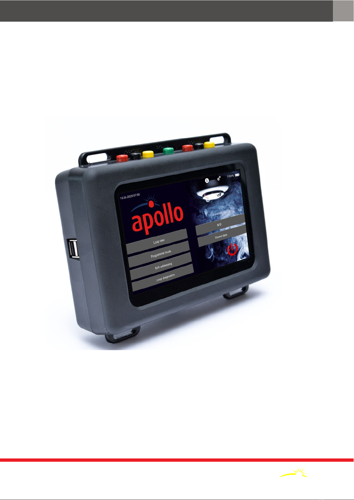
Apollo Test Set - User Manual
6PP2625 / 2020 / Issue 3
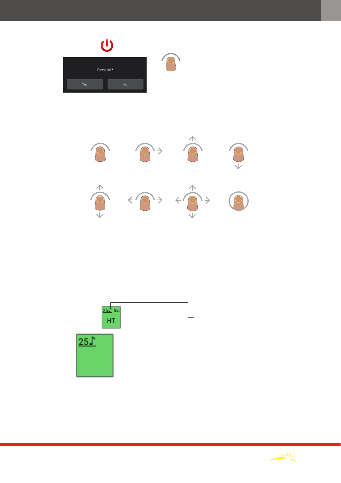
Device range ID Range Description
Dis Discovery covers all Discovery devices including Discovery UL
Sot Soteria all Soteria devices
XP XP95 covers XP95, XPlorer, XP95 I.S. and XPander devices
XPa XP95A used for XP95A devices with unique type codes
S90 Series 90 covers all Series 90 devices
U User covers all User type codes
Device type test set ID Description
SUM Shop Unit Monitor/User Defined
UD1 User Defined
UD2 User Defined
UD3 User Defined
SND
Sounder Controller, Sounders, Visual Indicators, VADs (Base and Open Area), Sounder Control Module
Sounders, Visual Indicators and VADs (Base and Open Area)
Sounder Control Module
Sounder Beacon Base and Open Area
Sounder Base
Voice Sounder Beacon
Voice Sounder
Open-Area Sounder
Reserved
VAD
Sounder Visual Alarm Device
Open-Area Sounder Visual Alarm Device
Visual Alarm Device Base
Open-area Visual Alarm Base
VID
Sounder Visual Indicating Device
Open-Area Sounder Visual Indicating Base
Visual Indicating Device Base
Open-Area Visual Indicating Device
I/O
Single Channel I/O Unit, Switch Monitor Unit, Three Channel I/O Unit and Three Channel I/O Unit (Analogue)
I/O Output Units and XP95A Relay Output Module
Input Unit (1 I/P, Faceplate and DIN-rail)
Output Unit (1 O/P, Faceplate and DIN-rail)
I/O Unit (1 I/P, 1 O/P, Faceplate and DIN-rail)
Mains I/O Unit (2 I/P, 1 O/P, Faceplate and DIN-rail)
I/O Unit (2 I/P, 2 O/P, Faceplate and DIN-rail)
Input Unit (4 I/P, Faceplate and DIN-rail)
I/O Unit (4 I/P, 4 O/P, Faceplate and DIN-rail)
MMM Mini Switch Monitor Module and Mini Monitor Module
SMM Switch Monitor Module
Switch Monitor I/O Module and 120 V I/O Module
ION Ionisation detector
CO CO Gaseous Fire Detector
COH
CO/Heat Multisensor (without isolator)
CO/Heat Multisensor (with isolator)
UL CO Base (Apollo USA)
ZMU Control Unit Monitor and Zone Monitor Unit
Zone Monitor Unit and XPander Interface