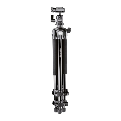
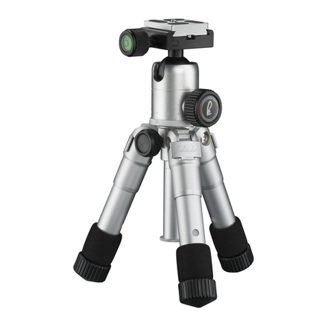
mantona Laurum 501 User manual

5
in
1
Laurum 501
19733man.indd 3 14.10.2013 15:21:37

2
1
2
3
6
7
9
11
12
13
8
4
5
10
19733man.indd 2 14.10.2013 15:21:37

3
1Schnellwechselplatte
mit 1/4 Zoll Gewinde 8Mittelsäule
2Sicherungsstift Stativplatte 9Kälteschutzgriff
3Feststellschraube
Panoramaeinstellung 10 Stativbein
4Festellhebel Kugelkopf 11 Gewinde zur Arretierung
der Stativbeine
5Arretierung Mittelsäule 12 Gewichthaken
6Hebel zur Beinwinkelverstellung 13 Gummifüße / Spikes
7Gewinde zur De-/Montage
der Stativbeine
1. Allgemeine Hinweise
• Achten Sie darauf, dass alle Schrauben fest angezogen sind
• Vorsicht bei der Beinwinkelverstellung - Quetschgefahr
• Die Schraubgewinde der Stativbeine sowie die Mittelsäule können mit
max. 3 Umdrehungen gelöst oder befestigt werden
• Gefahr von Beschädigungen durch Herunterfallen der Kamera bei nicht sachgerechter
Befestigung der Einzelteile
• Vergewissern Sie sich, dass vor jeder Benutzung Ihr Equipment sicher und fest sitzt
• Die Schnellwechselplatte ist kompatibel mit anderen Arca Swiss Schnellwechselplatten
2. Stativ-Variationen
1. Kamerastativ:
• Drehen Sie die Stativbeine um 180 Grad
• Stellen Sie sicher, dass die Stativbeine in ge-
wünschtem Winkel einrasten
• Drehen Sie die Arretierung an den Stativbeinen
um eine geeignete Höhe zu erreichen. Achten Sie
darauf, dass die Schraubgewinde nicht überdreht
werden
Bedienungsanleitung
19733man.indd 3 14.10.2013 15:21:37

4
2. Stativ mit gedrehter Mittelsäule
Möglichkeit 1:
Drehen Sie die Stativbeine um 180 Grad –
die Demontage einzelner Teile wird nicht benötigt
Möglichkeit 2:
Entfernen Sie den Stativhaken und drehen
Sie die Mittelsäule um 180 Grad
3. Einbeinstativ
Jedes Stativbein kann als Einbeinstativ verwendet werden
• Öffnen Sie durch Drehen das Gewinde an einem der Stativbeine
• Drehen Sie das Einbein heraus
• Montieren Sie die kurze Mittelsäule über das Gewinde am Einbeinstativ
• Montieren Sie die Stativplatte zur Montage für den Kugelkopf auf dem Einbein
• Befestigen Sie den Kugelkopf über das 3/8 Zoll Gewinde am Einbeinstativ
4. Lampenstativ
• Montieren Sie die Stativbeine des
Tischstativs
• Demontieren Sie die Mittelsäule durch
Entfernen des Stativhakens
• Ersetzen Sie die Mittelsäule durch
eines der Stativbeine
• Entfernen Sie den Gummiaufsatz am
Stativbein und montieren Sie das
Adapterstück sowie den Blitzschuh
19733man.indd 4 14.10.2013 15:21:38

5
5. Tischstativ
• Öffnen Sie die Arretierung an
den Stativbeinen
• Demontieren Sie die langen Stativbeine
• Montieren Sie die kurzen Stativbeine,
welche im Seitenfach der Tasche
enthalten sind
• Je nach Bedarf kann durch Entfernen
des Stativhakens die kurze Mittelsäule
eingeschoben und befestigt werden
Beinwinkelverstellung:
• Ziehen Sie an den Clips und achten Sie darauf, dass diese vollständig gelöst sind
• Arretieren Sie die Stativbeine in einem beliebigen vorgerasterten Winkel
• Wenn nötig, die Schrauben mit Hilfe des mitgelieferten Inbusschlüssels nachziehen
Spikes / Gummifüße
• Durch Drehen können Sie die Gummifüße entfernen
• Darunter benden sich die Spikes, welche besonders für
Outdoor-Einsätze geeignet sind
19733man.indd 5 14.10.2013 15:21:38

6
3. Kugelkopf
1gummierte Schnellwechselplatte
mit 1/4 Zoll Gewinde
2Kamera Bumper
3Sicherung Schnellwechselplatte
4Feststellschraube
Schnellwechselplatte
5Feststellung Stativkopf
6Feststellschraube für
horizontale Ebene
7Friktionsschraube
12
4
5
7
3
6
Allgemeine Hinweise
• Der Sicherungsstift verhindert ein ungewolltes Lösen der
Schnellwechselplatte bei geöffneter Feststellschraube
• Zum korrekten Befestigen der Platte muss der Stift
gedrückt werden und einrasten
• Der Kamera-Bumper verhindert das Verrutschen der
Platte bei montierter Kamera
• Durch Lockern der Feststellschraube kann der Stativ-
kopf bewegt werden. Die Friktionsschraube dient der
Einstellung des Kugelwiderstandes.
Demontieren der Stativplatte
• Öffnen Sie die Feststellschraube und lockern
Sie die Stativplatte
• Drücken Sie den Sicherungsstift
• Schieben Sie die Platte heraus
19733man.indd 6 14.10.2013 15:21:39

7
4. Technische Daten
Dreibeinstativ
Max. Höhe ca. 167 cm
Min. Höhe ca. 24 cm
Anschluss Stativ 3/8 Zoll
Länge Mittelsäule ca. 35 cm
Packmaß ca. 47 x 9 cm
Gewicht ohne Kugelkopf
Gewicht mit Kugelkopf
ca. 1,9 kg
ca. 2,25 kg
Max. Belastbarkeit ca. 12 kg
Material Aluminium
Einbeinstativ (mit Kopf)
Max. Höhe ca. 152 cm
Min. Höhe ca. 64 cm
Gewicht ca. 0,86 kg
Tischstativ (mit Kopf)
Max. Höhe ca. 60 cm
Min. Höhe ca. 32 cm
Gewicht ca. 1 kg
Lampen-/Blitzstativ (mit Kopf)
Max. Höhe ca. 145 cm
Min. Höhe ca. 58 cm
Gewicht ca. 0,8 kg
Lieferumfang:
Kamerastativ Laurum 501 mit Kugelkopf, inkl. 2 Mittelsäulen,
3 Tischstativbeinen, Stativtasche, Blitzadapter und 3 Inbusschlüssel
19733man.indd 7 14.10.2013 15:21:39

8
1
2
3
6
7
9
11
12
13
8
4
5
10
19733man.indd 8 14.10.2013 15:21:39

9
1Quick-release plate with 1/4 inch
thread 8Centre column
2Tripod plate locking pin 9Cold protection grip
3Locking screw for panorama setting 10 Tripod leg
4 Ball head xing knob 11 Thread for locking the tripod legs
5Centre column lock 12 Ballast hook
6Lever for leg angle adjustment 13 Rubber feet / spikes
7Thread for disassembling/
assembling the tripod legs
1. General notes
• Make sure that all screws have been tightened
• Be cautious with the leg angle adjustment - danger of pinching
• The screw threads of the tripod legs as well as the centre column can be loosened or
tightened by max. 3 turns.
• Danger of damage caused by the camera falling down, if the individual parts have not
been properly fastened
• Before each use make sure that your equipment has been properly installed and ts tightly.
• The quick-release plate is compatible with other Arca Swiss quick release plates.
2. Tripod variants
1. Camera tripod:
• Turn the tripod legs by 180 degree
• Make sure that the tripod legs click into place
under the desired angle
• Turn the lock on the tripod legs to adjust to a
suitable height. Take care not to overtighten the
screw threads.
Instruction Manual
19733man.indd 9 14.10.2013 15:21:39

10
2. Tripod with reversed centre column
Possibility 1:
Turn the tripod legs by 180 degree –
no parts need to be dismantled
Possibility 2:
Remove the tripod hook and turn the
centre column by 180 degree.
3. Monopod
Any tripod leg can be used as a monopod
• Turn the thread on one of the tripod legs to open
• Turn out the single leg
• Mount the short centre column via the thread on the monopod
• Mount the tripod plate for ball head installation on the monopod
• Fasten the ball head by using the 3/8 inch thread on the monopod
4. Lamp tripod
• Assemble the tripod legs of the table
tripod
• Disassemble the centre column by
removing the tripod hook
• Replace the centre column with one
the tripod legs
• Remove the rubber attachment on the
tripod leg ad mount the adapter and
the ash shoe mount
19733man.indd 10 14.10.2013 15:21:40

11
5. Table tripod
• Open the lock on the tripod legs
• Disassemble the long tripod legs
• Assemble the short tripod legs, which
are stored in the side compartment of
the bag
• By removing the tripod hook, the short
centre column can be retracted and
fastened, if required
Leg angle adjustment:
• Pull the clips and make sure that these have been loosened completely
• Lock the tripod legs at any pre-locked angle
• If necessary, tighten the screws with the supplied Allen key
Spikes / rubber feet
• The rubber feet can be removed by twisting
• The spikes, which are particularly suitable for outdoor use,
are then uncovered
19733man.indd 11 14.10.2013 15:21:40

12
3. Ball head
1Rubber coated quick-release
plate with 1/4 inch thread
2Camera bumper
3Lock for quick-release plate
4Locking screw for quick-release
plate
5Tripod head lock
6Locking screw for horizontal plane
7Friction screw
12
4
5
7
3
6
General notes
• The locking pin prevents accidental loosening of the
quick-release plate when the locking screw has been
loosened
• For correct fastening of the plate the pin must be
pressed and click into place
• The camera bumper prevents slipping of the plate with
camera mounted
• The tripod head can be moved after loosening the
locking screw. The friction screw serves the purpose of
adjusting the resistance of the ball.
Disassembling the tripod plate
• Loosen the locking screw and also the tripod plate
• Press in the locking pin
• Push the plate out
19733man.indd 12 14.10.2013 15:21:40

13
4. Technicalspecications
Tripod
Max. height ca. 167 cm
Min. height ca. 24 cm
Tripod connection 3/8 Zoll
Length of centre column ca. 35 cm
Transport size ca. 47 x 9 cm
Weight without ball head
Weight with ball head
ca. 1,9 kg
ca. 2,25 kg
Max. load bearing
capacity ca. 12 kg
Material Aluminium
Monopod (incl. head)
Max. height ca. 152 cm
Min. height ca. 64 cm
Weight ca. 0,86 kg
Table tripod (incl. head)
Max. height ca. 60 cm
Min. height ca. 32 cm
Weight ca. 1 kg
Lamp/ashtripod(withhead)
Max. height ca. 145 cm
Min. height ca. 58 cm
Weight ca. 0,8 kg
Scope of delivery:
Camera tripod Laurum 501 with ball head, incl. 2 centre columns,
3 table tripod legs, tripod bag, ash adapter and 3 Allen keys
19733man.indd 13 14.10.2013 15:21:40

14
1
2
3
6
7
9
11
12
13
8
4
5
10
19733man.indd 14 14.10.2013 15:21:41

15
1 Plateau de xation rapide avec
letage 1/4 pouce 8Colonne centrale
2Plateau du trépied avec goupille de
sécurité 9
Poignée de protection contre le froid
3Molette de réglage panoramique 10 Pied
4Levier de réglage rotule 11 Filetage pour blocage des pieds
5
Dispositif de blocage colonne centrale
12 Crochet de lestage
6Levier de réglage de l‘écartement
des pieds 13 Pieds en caoutchouc / pointes
7Filetage pour montage/démontage
des pieds
1. Remarques générales
• Vériez que les vis sont bien serrées.
• Prudence lors du réglage de l‘écartement des pieds : risque d‘écrasement
• Les fermetures vissées des pieds et la colonne centrale peuvent être serrées ou
desserrées en trois tours maximum.
• Risque de dommages suite à la chute de l‘appareil photo en cas de mauvaise
xation des composants.
• Assurez-vous avant chaque utilisation que votre équipement est sécurisé et
correctement xé.
• Le plateau de xation rapide est compatible avec d‘autres plateaux de xation
rapide Arca Swiss.
2. Déclinaisons du trépied
1. Trépied pour appareil photo:
• Faites pivoter les pieds à 180°.
• Assurez-vous que les pieds s‘enclenchent
correctement à l‘angle souhaité.
• Tournez le dispositif de blocage des pieds an
d‘obtenir la hauteur souhaitée. Veillez à ce que
les vis ne soient pas trop serrées.
Mode d‘emploi
19733man.indd 15 14.10.2013 15:21:41

16
2. Trépied avec colonne centrale tournée
Possibilité 1 :
Faites pivoter les pieds à 180°.
Le démontage des pièces n‘est pas nécessaire.
Possibilité 2 :
Retirez le crochet du trépied et faites pivoter
la colonne centrale à 180°.
3. Monopied
Chaque pied du trépied peut être utilisé comme monopied.
• Ouvrez le letage d‘un pied en le tournant.
• Retirez le pied en le faisant tourner.
• Montez la colonne centrale courte sur le letage du monopied.
• Montez le plateau du trépied pour installer la rotule sur le monopied.
• Fixez la rotule sur le monopied à l‘aide du letage 3/8 pouce.
4. Trépied pour lampe
• Montez les pieds du trépied de table.
• Démontez la colonne centrale en
retirant le crochet du trépied.
• Remplacez la colonne centrale par un
des pieds.
• Retirez l‘embout en caoutchouc du
pied et montez l‘adaptateur et le sabot
pour ash.
19733man.indd 16 14.10.2013 15:21:41

17
5. Trépied de table
• Ouvrez le dispositif de blocage des
pieds.
• Démontez les longs pieds.
• Montez les pieds courts situés dans le
compartiment latéral du sac.
• Si besoin, vous pouvez insérer et xer
la colonne centrale courte en retirant le
crochet du trépied.
Réglage de l‘écartement des pieds :
• Tirez sur les clips et assurez-vous qu‘ils soient bien complètement détachés.
• Bloquez les pieds dans un angle non gênant.
• Si nécessaire, resserrez les vis à l‘aide de la clé six pans fournie.
Pointes / pieds en caoutchouc
• Vous pouvez retirer les pieds en caoutchouc en les faisant
tourner.
• Les pointes se trouvent en dessous et sont particulièrement
adaptées à une utilisation en extérieur.
19733man.indd 17 14.10.2013 15:21:41

18
3. Rotule
1 Plateau de xation rapide en ca-
outchouc avec letage 1/4 pouce
2Butoir appareil photo
3 Protection plateau de xation
rapide
4Molette de réglage plateau de
xation rapide
5Serrage rotule
6Molette de réglage pour niveau
horizontal
7Vis de friction
12
4
5
7
3
6
Remarques générales
• La goupille de sécurité empêche le desserrage involon-
taire du plateau de xation rapide lorsque la molette de
réglage est ouverte.
• Pour xer correctement le plateau, la goupille doit être
enfoncée et insérée.
• Le butoir de l‘appareil photo empêche le plateau de
glisser lorsque l‘appareil est monté dessus.
• La rotule peut être bougée en desserrant la molette de
réglage. La vis de friction permet de régler la résistance
de la rotule.
Démontage du plateau du trépied
• Ouvrez la molette de réglage et desserrez le
plateau du trépied.
• Appuyez sur la goupille de sécurité.
• Retirez le plateau.
19733man.indd 18 14.10.2013 15:21:42

19
4. Caractéristiques techniques
Trépied à trois pieds
Hauteur max. ca. 167 cm
Hauteur min. ca. 24 cm
Raccord du trépied 3/8 Zoll
Longueur colonne
centrale ca. 35 cm
Dimensions ca. 47 x 9 cm
Poids sans rotule
Poids avec rotule
ca. 1,9 kg
ca. 2,25 kg
Capacité de charge max.
ca. 12 kg
Matériau Aluminium
Monopied (avec rotule)
Hauteur max. ca. 152 cm
Hauteur min. ca. 64 cm
Poids ca. 0,86 kg
Trépied de table (avec rotule)
Hauteur max. ca. 60 cm
Hauteur min. ca. 32 cm
Poids ca. 1 kg
Trépiedpourlampe/ash(avecrotule)
Hauteur max. ca. 145 cm
Hauteur min. ca. 58 cm
Poids ca. 0,8 kg
Éléments fournis :
Trépied pour appareil photo Laurum 501 avec rotule, deux colonnes centrales, trois pieds
pour trépied de table, un sac pour trépied, un adaptateur de ash et trois clés six pans
19733man.indd 19 14.10.2013 15:21:42

20
1
2
3
6
7
9
11
12
13
8
4
5
10
19733man.indd 20 14.10.2013 15:21:42
Table of contents
Languages:
Other mantona Camera Accessories manuals