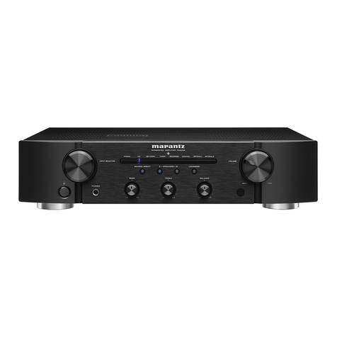
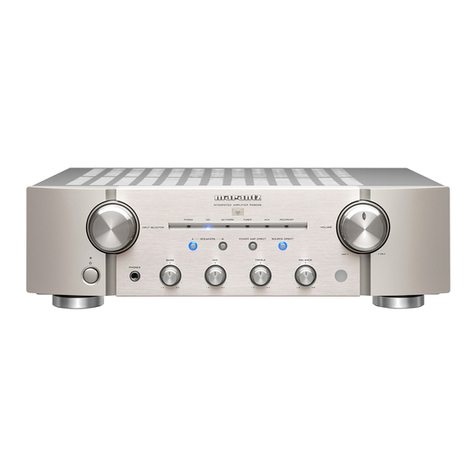
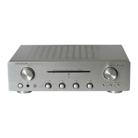
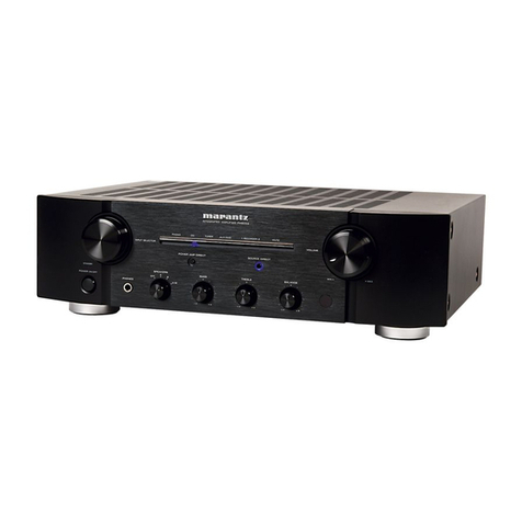
Marantz Pm-6a User manual


MARANTZ
DESIGN
AND
SERVICE
Using
superior
design
and
selected
high
grade
components,
MARANTZ
company
has
created
the
ultimate
in
stereo
sound.
Only
original
MARANTZ
parts
can
insure
that
your
MARANTZ
product
will
continue
to
perform
to
the
specifications
for
which
it
is
famous.
Parts
for
your
MARANTZ
equipment
are
generally
available
to
our
National
Marantz
Subsidiary
or
Agent.
ORDERING
PARTS:
Parts
can
be
ordered
either
by
mail
or
by
telex.
in
both
cases,
MARANTZ
part
number
has
to
be
specified.
!f
you
order
by
_
mail,
fulfil
MARANTZ
order
forms.
MARANTZ
S.A.
EUROPEAN
PARTS
DEPARTMENT
.
2,
Avenue
Léopold
III
B-7120
PERONNES-lez-BINCHE
BELGIUM
5
TWX:
57589
SEPLT
B
The
following
information
must
be
supplied
to
eliminate
delays
in
processing
your
order:
Complete
address
Complete
part
numbers
and
quantities
required
Description
of
parts
Model
number
for
which
part
is
required
Way
of
shipment
Signature:
any
order
form
or
telex
must
be
signed
otherwise
such
part
order
will
be
considered
as
null
and
void,
An
PWN
=
PARTS
ORDERING:
Parts
may
be
ordered
from
the
following
addresses:
EUROPE
MARANTZ
S.A.
MARANTZ
NORSKE
A.S.
MARANTZ
DENMARK
MARANTZ
GMBH
AUSTRIA
European
Parts
Department
Refstadalleen
13
Bregnergdvej
132b
Wiedner
Hauptstrasse
98
2,
Avenue
Léopold
III
Oslo
5
3460
Birkergd
1050
Wien
B-7120
Péronnes-lez-Binche
Norway
Denmark
Austria
Belgium
Telex:
19659
Telex:
39137
Telex:
113583
Telex:
57589
MARANTZ
S.A.
MARANTZ
FRANCE
MARANTZ
BELGIUM
MARANTZ
SVENSKA
A.B.
326
Avenue
Louise
Bte
32
4
Rue
Bernard
Palissy
45
Rue
Auguste
Van
Zande
Svartviksvangen
56
1050
Brussels
92600
Asniéres
1080
Brussels
Traneberg
-
Box
12016
Belgium
France
Belgium
16112
Bromma
Telex:
26602
Telex:
611651
Sweden
Telex:
13449
MARANTZ
GERMANY
GMBH
MARANTZ
AUDIO
U.K.
LTD.
Max
Planckstrasse,
22
Unit
15/16
6072
DREIEICH
1
Saxon
Way
Industrial
Estate
West
Germany
Moor
Lane
Telex:
4185316
Harmondsworth
UB7
OLW
Great
Britain
Telex:
935196
AUSTRALIA
MARANTZ
AUSTRALIA
PTY.,
LTD.
32
Cross
Street
Brookvale,
N.S.W.
2100
Australia
Telex:
24121
All
of
the
above
locations
are
fully
equipped
to
take
care
of
your
total
service
needs.
Because
various
countries
have
differing
configuration
requirements,
it is
necessary
that
you
contact
the
service
facility
in
your
particular
country.
in
the
event
that
there
is
no
service
location
listed
for
your
country,
please,
contact
the
nearest
facility
for
the
necessary
assistance.
In
case
of
difficulties,
do
not
hesitate
to
contact
the
Technical
Department
at
abovementioned
address.
ERR
em
Been
BRE
Z*

TABLE
OF
CONTENTS
INTRODUCTION:
i
sceces
ccccetn
Se
lore
hh
ee
Sree
ee
heat
aes
a
BMA
SR
a
Gs
WB
ake
aa
are
amc
as
1
1:
HRBEATURES
woireue
at
oo
pce
este
ode
en
acl
eeties
Rapti
Aale
Wien
aA
Bee
GDR
ele
rbot
hk
Ste
Baan
1
2.
PAW
BOARDS
yiceadlsc
ieee
cee
aoa
aed
soceret
ganesh
al
anata
Ga
eee
ORE
RE
RA
a
We
a
pa
See
Pe
2
3.
TEST
EQUIPMENT
REQUIRED
FOR
SERVICING
............
0.0002
cece
ee
eee
eens
3
4.
ADJUSTMENT
PROCEDURES
............
0.0.0
ccc
ce
ee
eee
eee
e
ete
enn
eeaes
3
5.
VOLTAGE
CONVERSION
..
10...
0...
ccc
cc
ee
ete
ee
ete
eee
eee
eens
4
6...
BROCK
DIAGRAM
asi
ce
ociod
ech
eek
kel
oe
Bee
Seared
edb
8
Was
EO
Sie
ew
SE
eae
and
ee
Se
es
5
7.
DIAGRAM
AND
COMPONENT
LOCATIONS
.............0
cc
cece
eee
ere
eee
teens
6
7.1.
Filter
Assembly
(PHOO)
Schematic
Diagram
and
Component
Locations............000
ee
eee
eteees
6
7.2
Speaker
Switch
Assembly
(PW00)
Schematic
Diagram
and
Component
Locations
............202e0005
6
7.3.
Voltage
Amp.
Assembly
(P700)
Schematic
Diagram
and
Component
Locations
.............00200205
6
7.4
Ripple
Filter
Assembly
(PCOO)
Schematic
Diagram
and
Component
Locations
......:......0+020208%
6
75
Loudness
Assembly
(PFO0)
Schematic
Diagram
and
Component
Locations
............000
000s
e
eee
6
76
ASO
Protector
Assembly
(PNOO)
Schematic
Diagram
and
Component
Locations
.........
gang
a
ar
tede
an
Soat
7
7.7
Test
Point
Assembly
(PJOO)
Schematic
Diagram
and
Component
Locations
.............00
000
eters
7
78
Tone
Amp.
Assembly
(PEO1)
Schematic
Diagram
and
Component
Locations...............00
000802
8
79
Tone
On-Off
Assembly
(PS00)
Schematic
Diagram
and
Component
Locations
............00002+
000%
8
7.10
Pre-Amp.
Assembly
(P400)
Schematic
Diagram
and
Component
Locations
..............0200e00888
9
7.11
Transistor
Block
Assembly
(P401)
Schematic
Diagram
and
Component
Locations
............0000005
9
7.12
MC
Transistor
Block
Assembly
(PM01)
Schematic
Diagram
and
Component
Locations
..........-+++-.
9
7.13
Head
Phone
Assembly
(PX00)
Schematic
Diagram
and
Component
Locations
............-.2008880
8%
10
7.14
A-B
Detector
Assembly
(PLOO)
Schematic
Diagram
and
Component
Locations
.............22+2205
11
7.15
A-B
Power
Switch
Assembly
(PKO0)
Schematic
Diagram
and
Component
Locations
...........---++5
11
7.16
Power
Amp.
Assembly
(P600)
Schematic
Diagram
and
Component
Locations
.............
00200228
12
7.17
Mode/Balance/Vol.
Assembly
(PGOO)
Schematic
Diagram
and
Component
Locations
.........-+-.+-+-
12
7.18
L.E.D.
Power
Ind.
Assembly
(PY00)
Schematic
Diagram
and
Component
Locations
............08065%
13
7.19
Phone
Input
Assembly
(PV00)
Schematic
Diagram
and
Component
Locations
............0.-2+¢e55
13
8.
EXPLODED
VIEW
AND
PARTS
LIST
.........
0.0.0...
cece
ee
eee
14
9;
PLEGTRICAL,
PARIS
LIST
4c4ca
vias
ier
Pa
inanel
et
nenetamarne
toa
haee
USE
coelate
21
10.
TECHNICAL
SPECIFICATIONS
.........
0.0.00.
cece
ec
eee
ee
ete
nee
eee
ene
30
11.
SCHEMATIC
DIAGRAM
.......
cc
cc
ccc
ccc
ce
te
ce
te
cet
eee
erence
een
etenee
32

MARANTZ
MODEL
Pm-6A
STEREO
PRE
MAIN
AMPLIFIER
INTRODUCTION
This
service
manual
was
prepared
for
use
by
Authorized
Warranty
Staions
and
contains
service
information
for
the
Marantz
Model
Pm-6a
Stereo
Pre
Main
Amplifier.
Servicing
information
and
voltage
data
included
in
this
manual
are
intended
for
use
by
knowledgeable
and
ex-
perienced
personnel
only.
All
instructions
should
be
read
carefully.
No
attempt
should
be
made
to
proceed
without
a
good
understanding
of
circuitry
operation.
The
parts
list
furnishes
complete
ordering
information.
Most
replacement
parts
should:
be
ordered
from
the
Marantz
Company.
However,
a
simple
description
is
included
for
parts
which
can
be
obtained
locally.
coveiiie
wees
nectean
TREY
See
1.
FEATURES
@
MC
Head
Amplifier
(13
transistors
for
each
channel)
The
first
stage
of
the
MC
head
amplifier
is
a
push-pull
amplifier
consisting
of
4
very
low
noise
NPN
transistors
and
4
very
low
noise
PNP
transistors.
The
second
stage
is
also
a
push
pull
amplifier,
and
the
output
stage
is
a
SEPP
amplifier.
The
feedback
circuit
impedance
is
reduced
as
much
as
possible
to
improve
the
S/N
ratio,
and
a
voltage
gain
of
20
dB
(10
times)
is
obtained
at
a
rated
input
level
of
125
uV.
@
PHONO
Amplifier
(11
transistors
for
each
channel)
The
PHONO
amplifier
uses
a
full
push-pull
circuit
con-
sisting
of
11
transistors
for
each
channel
so
that
low
TIM
distortion
and
a
high
S/N
ratio
are
obtained.
The
first
stage
is
a
push-pull
circuit
consisting
of
very
low
noise,
high
Gm
N
and
P
channel
FETs
combined
with
a
cascode
current
Miller
circuit
so
that
degradation
of
following
stage
characteristics
due
to
input
stage
im-
pedance
fluctuation
is
prevented.
The
second
stage
consists
of
an
emitter
follower
buffer
amplifier
and
a
push-pull
voltage
amplifier.
The
output
stage
uses
a
SEPP
circuit
which
is
adequate
to
drive
any
type
of
load.
The
equalizer
elements
have
very
low
impedances
compared
with
conventional
circuits
so
a
S/N
ratio
of
90
dB
is
obtained
at
the
rated
input
level.
The
equalizer
elements
are
metal
film
resistors
with
tolerances
of
1%
and
polypropylene
capacitors
with
tolerances
of
2%;
this
makes
it
possible
to
obtaine
an
RIAA
phono
equalization
of
+0.2
dB
over
the
audio
range
from
20
Hz
—
20
kHz.

Input
impedances
27
kQ,
47
kQ
and
100
kQ
are
provided
for
different
types
of cartridges
when
the
PHONO
1
input
is
selected.
The
PHONO
amplifier
output
circuit
is
provided
with
a
relay
to
mute
undesirable
noise
when
the
power
is
switched
ON
and
OFF,
and
with
a
EQ
subsonic
filter
to
reduce
turntable
rumble
and
flutter.
Quarter
A
System
The
quarter
A
system
automatically
switches
the
bias
current
and
supply
voltage
to
the
main
amplifier
by
de-
tecting
the
main
amplifier
input
voltage
and
speaker
current;
thus,
the
main
amplifier
operates
in
class
A
when
the
power
output
is
up
to
30W/8Q,
and
in
class
AB
when
the
power
output
exceeds
that
level.
The
phase
correction
circuit
in
the
detection
circuit
prevents
distortion
from
being
generated
even
if
a
wave-
form
with
a
sharp
rising
edge
is
applied.
Marantz’s
usual
superb
amplifier
circuit
has
not
been
altered
in
this
system,
except
that
the
detection
circuit
is
connected
to
the
signal
system.
Voltage
amplifier
The
input
circuit
of
the
voltage
amplifier
is
a
source
follower
using
a
pair
of
FETs,
so
variation
in
the
im-
pedance
of
this
stage
does
not
influence
following
stage
characteristics.
The
next
circuit
is
a
differential
amplifier
using
a
dual
transistor,
followed
by
an
active
balance
loading
circuit
using
a
dual
transistor.
One
of
the
differential
amplifier
output
signals
is
phase-
inverted,
then
both
signals
are
applied
to
the
push-pull
amplifier
through
the
emitter
follower
buffer.
Power
amplifier
The
power
amplifier
employs
triple
Darlington
connection
and
supper
high
f—
power
transistors
connected
in
paral-
lel.
The
power
amplifier
uses
unique
push-pull
circuit
with
ex-
cellent
open
loop
characteristics
and
a
2-pole
phase
com-
pensation
circuit,
so
the
frequency
response
is
flat
even
at
high
frequencies
and
TIM
distortion
is
reduced
remark-
ably,
Other
features
The
speaker
protection
circuit
uses
a
high
performance
IC
and
relay.
The
power
supply
circuit
uses
a
large
trans-
former
with
high
regulation
and
newly
developed,
large
capacity
custom
electrolytic
capacitors.
To
obtain
continuous
high
power
output,
high
efficiency
heat
pipes
are
used
to
radiate
the
heat
produced
by
the
power
transistors.
2.
P.W.
BOARDS
As
can
be
seen
from
the
circuit
diagram
the
chassis
of
Model
Pm-6a
consists
of
the
following
units.
Each
unit
mounted
on
a
printed
circuit
board
is
descrided
within
the
square
enclosed
by
a
bold
dotted
line
on
the
circuit
diagram.
wie
etd
a
i
etd
td
OWONAMAWN=|
—_
SOMNOTARWN
A
.
Pre-Amp.
........--
mounted
on
.
Transistor
Block
.....
mounted
on
.
Power
Amp.
.......
mounted
on
.
Voltage
Amp.
......
mounted
on
Ripple
Filter
.......
mounted
on
.
Tone
Amp.
........
mounted
on
.
Loudness
.........
mounted
on
.
Mode/Balance/Vol.
...
mounted
on
SF
HteR
ss.
eet
ees
mounted
on
.
TestPoint.........
mounted
on
.
A-B
Power
Switch.
...
mounted
on
.
A-B
Detector
.......
mounted
on
.
MC
Transistor
Block
..
mounted
on
.
ASO
Protector
......
mounted
on
Tone
On-Off
.......
mounted
on
.
Phone
Input
.......
mounted
on
.
Speaker
Switch
.....
mounted
on
.
Head
Phone...
.....
mounted
on
L.E.D.
Power
Ind..
...
mounted
on
P.W.
P.W.
P.W.
P.W.
P.W.
P.W.
P.W.
P.W.
P.W.
P.W.
P.W.
P.W.
P.W.
P.W.
P.W.
P.W.
P.W.
P.W.
P.W.
Board
P400
Board
P401
Board
P600
Board
P700
Board
PCO0O
Board
PEO1
Board
PFOO
Board
PGOO
Board
PHOO
Board
PJOO
Board
PKOO
Board
PLOO
Board
PM01
Board
PNOO
Board
PSOO
Board
PV00
Board
PW00
Board
PX00
Board
PYO0

3.
TEST
EQUIPMENT
REQUIRED
FOR
SERVICING
This
table
lists
the
test
equipment
required
for
servicing
the
Model
Pm-6a
Stereo
Pre
Main
Amplifier.
Distortion
Analyzer
Audio
Oscillator
AC
VTVM
Oscilloscope
Circuit
Tester
DC
VTVM
aa
|
Use
Distortion
measurements
Sinewave
and
squarewave
signal
source
LLL
Voltage
measurements
(AC)
Waveform
analysis
and
trouble
shooting
and
ASO
alignment
Trouble
shooting
—
AC
Wattmeter
Line
Voltmeter
Variable
Autotransformer
(0
~
140V
AC,
10A)
Shorting
Plug
Voltage
measurements
(DC)
Monitors
primary
power
to
amplifier
Monitors
potential
of
primary
power
to
amplifier
Adjust
level
of
primery
power
to
amplifier
lezen
4.
ADJUSTMENT
PROCEDURES
@
Bias
Current
Adjustment
(1)
(2)
Class
B
Connect
JL15
and
JL12
with
a
jumper.
Parts
adjusted:
RL43
and
RL44
Input:
~
Output:
8Q
load
Adjustment:
Connect
a
digital
voltmeter
between
JJO1
and
JJO2
(for
the
L
channel)
or
between
JJO3
and
JJ04
(for
the
R
channel).
Wait
until
the
voltage
stabilizes
(30-60
seconds),
then
adjust
RL43
or
RL44
so
that
the
voitmeter
reads
14
mV.
Class
A
Parts
adjusted:
RL39
and
RL40
Input:
-
Output:
8Q
load
Adjustment:
|
Connect
a
digital
voltmeter
between
JJO1
and
JJO2
(for
the
L
channel)
or
between
JJO3
and
JJO4
(for
the
R
channel).
Wait
until
the
voltage
stabilizes
(30—60
seconds),
then
adjust
RL43
or
RL44
so
that
the
voltmeter
reads
370
mV.
Shorts
amplifier
input
to
eliminate
noise
pickup

5.
VOLTAGE
CONVERSION
6.
BLOCK
DIAGRAM
@
EUROPEAN
MODEL
ONLY
TAGE
POWER
SUPPLY
To
convert
the
unit
to
a
different
power
source
voltage,
change
the
position
as
illustrated
in
the
drawing
below.
CAUTION
DISCONNECT
POWER
SUPPLY
CORD
FROM
AC
OUTLET
BEFORE
CONVERTING
VOLTAGE.
LOW
VOL
CIRCUIT
SWITCHING
O—“
|]
HEAD
PHONES
SPEAKER
PROTECTION
OuTPUT
HIGH
VOLTAGE
OWER
SUPPLY
E
SPK
SYSTEM
Voltage
Conversion
Chart
&
w
el
=o
a
=
°
I<
Es
>
oO
q a
x
=o
5
oz
a
53
°
aE
3
3
a
aa
c
s
fo}
aq
>
FLAT
AMP
TONE
AMP
_
N
= =
Ww
WwW
8
o
¢&
&
Ww
>
WwW
~
‘
Z
e
2
=
=)
LU
gy
3
g
a
o
[om
s
>
B
S
@
cS)
2a
2
ot
a
@
VOLTAGE
SELECTOR
x
=|
a
qt
7
N
ph
Ee
nat.
28
[fb
s
a
fo}
oO
Nn
w
We
a
g
2
48
|
Note
on
safety:
Symbol
A\
Fire
or
electrical
shock
hazard.
Only
orignal
parts
z
-
&«
should
be
used
to
replace
any
part
marked
with
symbol
A
.
3
Any
other
component
substitution
(other
than
original
Py
type),
may
increase
risk
of
fire
or
electrical
shock
hazard.
-§
©
©)
o
x
=
*
s
N
}
o
Ess
re)
am
a
re)
s
a
ae
2 2
re
<
zoe
a
ge
of
@
aed
a
a
ie
2
Pas
5
5

7.
DIAGRAM
AND
COMPONENT
LOCATIONS
7.1
Filter
Assembly
(PHOO)
Schematic
Diagram
and
Component
Locations
7.3
Voltage
Amp.
Assembly
(P700)
Schematic
Diagram
and
Component
Locations
|
PHOO
|
P700
;
R751
2.76(2W)
er
|
QHO!
~
1/2
cHOS
4.7/25V
R755
2.2
R74
2k
CT
0.47
Pare
on
Ce
O
ov
BK
OL
bo
@_®
721
Law
gh
9
Sea
eees
7.6
ASO
Protector
Assembly
(PNOO)
7.2
Speaker
Switch
Assembly
(PW00)
~
Schematic
Diagram
and
Component
Locations
Schematic
Diagram
and
Component
Locations
5
P¥aQGi-w?
GISOHISSHY
7.5
Loudness
Assembly
(PF00)
Schematic
Diagram
and
Component
Locations
[PFOO
_
couoness
7.7
Test
Point
Assembly
(PJ00)
Td
Schematic
Diagram
and
Component
Locations
ee
ee
O
JJO1
JJOZ
CERTHSSS
HNIO3
xe
WLHAD

P400
ms
ane
sue
.
7.8
Tone
Amp.
Assembly
(PE01)
Schematic
Diagram
and
Component
Locations
me
tae
F
Ectoe,
ae
|
7.10
Pre-Amp.
Assembly
(P400)
Schematic
Diagram
and
Component
Location
>
RS
=
*
.
oer
Saou,
TES
nm
QMOl
~
QM04
|e
+
‘i
=
-—to
|
i
PY
—QMo9
~
OMI2
ov
fey
|
|
j
404
oe
Hf
8
F.—Ff
toil
,
onl
1
o
fg
1°
Fee
nt
\
ak
33"
a1
i
|ele
ee
2
me
HB
3
i
Ts
es
er
|
a
5
—=C5
3
&
—
——
I
|
I
2
wh
|
:
pS)
|
TUNER
8
sav
|
t
EHR
ae
|
eee
|
pes,
($402)
RES!
RE!
QE52
be
is
270/2WIS
270
(I/2W)
eS!
JESS
:
|
©
©
°
a
e
Hey
|
|e
|
O+©
|
;
ine
}
7.11
Transistor
Block
Assembly
(P401)
a
°
Schematic
Diagram
and
Component
Locations
O+F+©
7.9
Tone
On-Off
Assembly
(PS00)
Schematic
Diagram
and
Component
Locations
|
_
O+F©
AKSSJHI250_
bik
)
@)
j
O+4F-©
Ra65
220
|
eas,
an
Rags
220!
0
1
©
Oo
L4or
Base
220
|
,
—
;
%
R464
560
7.12
MC
Transistor
Block
Assembly
(PM01)
Schematic
Diagram
and
Component
Locations
12
1
i
SOURCE
t
SOURCE
2-1
2
TAPE
COPY
TAPE
MONITOR
(s403)
(s401)

mM
!
|!
oa
I
8
;
2
9
LJ
'saor
|8
\saoz
|2
1
ae
'
oO
Leo}
©
©
©)
Us
Us
Us
ed
Big
pe)
QMO!l
~
QM04
QMO9
~
QMI2
QMI3
~
QMI6
QMO05
~
OMO8
[J],
-260
©
HO)
©
733V
MOB
RM
470(6)
5.6K
TUNER
-
1
PHONO
iv,
inane
TVs
AUX
OP
°
°
—-
Re04
-1.4V
oe
INPUT
SELECTOR
WOOK)
3
CH
12.0
($402)
Race.
hae
0407
$
Rg
—
oO
4
re
O-
_
1
°
|
©
©)
‘
a
a
4401
oot
tty
|
8
0
i
oot
Pod
|
|
Fe
4
|
©
(0)
owed
|
:
o
i
Oo
H
aa
|
2
i
©
©)
1402
©
©)
oO
©
©)
|
4403
©
©)
r
9
1
i
0
b-eo
1
oO
1
Rass
220)
©
LL.
bo
i
9
R464
560
o-
S4zi
S422
12
SOURCE
2-1
TAPE
COPY
TAPE
MONITOR
($403)
€
©
Rao!
39K(6)
Rao
[
Cty
o
o
R40;
©
ports)
&
oz
R.
1OOKIG)
z8
Q403
M24
8.0015,
'CM23
0.0015
Rail
tk
(6)
25.0V
0405
ed
401
Ye
ov
r)
—Wwy——
R408
100K
C423
0.0015
1}-————
R459
220K
1
t
SOURCE
2
$401)
Cell
220/35V
R80D
_Ce0R
/50V
n+
5.k
>
He
C82
220/35V
415
7.10
Pre-Amp.
Assembly
(P400)
Schematic
Diagram
and
Component
Locations
7.11
Transistor
Block
Assembly
(P401)
Schematic
Diagram
and
Component
Locations
7.12,
MC
Transistor
Block
Assembly
(PM01)
Schematic
Diagram
and
Component
Locations
7.13
Head
Phone
Assembly
(PX00)
Schematic
Diagram
and
Component
Locations
EF

7.14
A-B
Detector
Assembly
(PLOO)
Schematic
Diagram
and
Component
Locations
7.16
Power
Amp.
Assembly
(P600)
Schematic
Diagram
and
Component
Locations
[coo
AKSS
\
PLOO
=
wal
tered
dee
oo
kes
ae
5
a
“
Oy”
OF.
at
|
aa2
betes
“jL09
Sah
OS
i
nas
|
CWK-33x0
ible
o2
Oo
poe
2
RL3S
1
4
]
RL32
10K
Q606
619
630
6
|0.6v
=RESO
)
6!
|\roav,
22,
1A
1?
TE
rT)
a
RL33
2.2
=
CLI3
20p
i
eR
Bg
ca
ded
:
QLi2
uw
8
fas
|
i
RLIG
Wk
Quis
aos
7
6
RL24
2.2k
a
a
$
QLo2
2/2
QLO3
4/4
|
|
5
J
pee
8
i
he
s
$
C635
Rest
ney:
aa
aT!
5]
|e
22
2i
fi23
Loh,
few)
26
fo
B
Comme}
Oa
Soma)
Home
amas
jes
()
mee
<n
we
FOS
&
7.15
A-B
Power
Switch
Assembly
(PKO0)
Schematic
Diagram
and
Component
Locations
Lat
KOS
1
2
ol
.
j
3
Sue
aee
=
RKOL
2.2%
11
12

7.16
Power
Amp.
Assembly
(P600)
Schematic
Diagram
and
Component
Locations
|
P600
63V
(26.5V)
1
2
3
4
a
7.18
L.E.D.
Power
Ind.
Assembly
(PY00)
*g*
iy
"See
Schematic
Diagram
and
Component
Locations
a
rs
Lee
7.19
Phone
Input
Assembly
(PV00)
Schematic
Diagram
and
Component
Locations
1
2
5.
cvol

8.
EXPLODED
VIEW
AND
PARTS
LIST
e@
[C01-99]
Front
Panel
PART
NO.
DESCRIPTION
221H063400
221H063010
2461063030
2144160020
221H063020
51060305A9
2461271010
51042610A0
53112603A0
51100204E0
1143259010
2978259110
2978259010
2462259010
BA
AONNNAN
HABA
a=
Front
Panel
Assembly
Escutcheon,
Front
Panel
Escutcheon,
Pocket
Frame
Bracket
Escutcheon,
Pocket
Panel
P.H.M.
Screw
P3x5
Holder
F.H.M.
Screw
Hexagon
Nut
B.H.M.
Screw
B2x4
Bushing,
Pin
Holder
Bushing,
Push
Switch
Bushing,
Power
Switch
Bushing,
LED
F2.6
x
10
14
PART
NO.
e(E):
for
Europe
e
(F):
for
Japan
DESCRIPTION
2461063440
2461063050
2461253210
2461254010
2461254020
53110303E9
2461107020
2112053030
227H154010
2144154010
51500306B0
51280308U0
Pocket
Cover
Assembly
Escutcheon,
Pocket
Cover
Handle
Pin
Pin
Hexagon
Nut
Sheet
Cover
Knob
Knob,
Lever
Switch
F.H.
Tapped
Screw
B.H.
Tapped
Screw

e@
[C02-99]
Top
Cover
2461257010
2965118010
2991259110
5126030820
222H861020
222H861010
5148040629
59030805S0
‘TY
PART
NO.
DESCRIPTION
Lid,
Top
Cover
Spacer
Bushing
Tapped
Screw
3x8
Label
Label
F.
Washer
Screw
4x6
Washer
PART
NO.
2144257010
51280410U0
51280406U0
2759057010
51570410U0
51570410S0
2911861140
2911861110
e(€):
for
Europe
e@(F):
for
Japan
DESCRIPTION
Lid,
Bottom
Cover
B.H.
Tapped
Screw
B.H.
Tapped
Screw
Leg
P.
Taptite
Screw
P.Taptite
Screw
Label
Label

e@
[C03-99]
Rear
Panel
t
PKOO
Pvoo
COI7
OIGE(F
)
cole
&—
OISE(N)
e(&):
for
Europe
e
(F):
for
Japan
(F)
DESCRIPTION
=
221H160220
|
Bracket,
Rear
Panel
-221H160210
Bracket,
Rear
Panel
5110030889
B.H.M.
Screw
B3
x
8
51280308U0
|
B.H.
Tapped
Screw
B3x8
51280308U0
B.H.
Tapped
Screw
B3x8
1455259040
Bushing
1455259090
Bushing
51280308U0
|
B.H.
Tapped
Screw
83x
8
51260308Z0
|
B.T.
Screw
B3x8
62040029W0
|
Lug
DF17474510
|
Film
Cap.
0.47uF
+20%
DF17474510
|
Film
Cap.
0.474F
+20%
FS10400600
Fuse,
4A
FS10800600
Fuse,
8A
YJ08000290
Jack,
Fuse
Holder
YJO8000300
|
Jack,
Fuse
Holder
YT01080030
|
Terminal,
Speaker
System
YJO04000950
;
Jack,
AC
Outlet
YJ04000950
|
Jack,
AC
Outlet
YJ04000950
Jack,
AC
Outlet
YT01010050
|
Terminal,
GND
BYO5080010
|
Voltage
Selector
=—=NN
NNA=—
~"~NN
jRaEnn—
51280308U0
B.H.
Tapped
Screw
B3x8
51260308Z0
B.T.
Screw
B3
x8
221H267010
|
Heatsink
201H053030
Cover,
Voltage
Selector
51780312Z0
Fin
Neck
B.T.
Screw
B3
x
8
51280308U0
B.H.
Tapped
Screw
B3x8
51280310U0
|
B.T.
Screw
B3
x
10
51780312Z0
Fin
Neck
8.T.
Screw
B3
x8
4581861010
Label
404H160030
|
Bracket
51280308U0
|
B.H.
Tapped
Screw
.B3x8
51280308B0
|
B.H.
Tapped
Screw
B3x8
51280308B0
B.H.
Tapped
Screw
B3x8
-NO
YCO01800220
|
A.C.
Power
Cord
YC02400180
|
A.C.
Power
Cord
2147863010
Hang
Tag
YQ01000020
|
Shote
Plug
22
ew
oe
PAYA
=
2112265010
Indicator

@
[P01-99]
Front
Chassis
and
General
Parts
e@(E):
for
Europe
e(F):
for
Japan
PART
NO.
DESCRIPTION
PART
NO.
DESCRIPTION
2970154630
Knob,
Push
Switch
2144259110
Bushing,
Lever
Switch
$R00050110
Rotary
Switch,
Phone
Selector
$C00030010
Switch,
Input
Selector
$C00030010
Switch,
Tape
Copy
5126030820
|
B.T.
Screw
B3
x
8
$C00030010
|
Switch,
Tape
Monitor
51280308B0
B.H.
Tapped
Screw
B3x8
“5
SP01010410
Push
Switch
Power
2144160010
Bracket,
Front
Chassis
SP01010540
Push
Switch
Power
51100306A9
|
B.H.M.
Screw
B3
x6
51100306A9
|
B.H.M.
Screw
B3
x6
51100306A9
|
B.H.M.
Screw
B3
x6
51100306A9
|
8.H.M.
Screw
B3x6
51280308B0
B.H.
Tapped
Screw
8B3x8
2129005010
Clamper
2144109020
Shield
DK18103840
|
Ceramic
0.01uF
BF10400030
|
Cap.
Comp.0.1uF
+1202
51100306A9
|
B.H.M.
Screw
B3
x6
223H303010
|
Mask
7
NNSSNNNNGA
NN=--NNNNG—>
403H160040
|
Bracket
51280308B0
B.H.
Tapped
Screw
5128030880
B.H.
Tapped
Screw’
NN

e
(E):
for
Europe
@
[P02-99]
Main
Amp.
P.W.
Board
and
Heatsink
e(F):
for
Japan
coos~col2
co005~C008
PART
NO.
DESCRIPTION
PART
NO.
DESCRIPTION
042L—_#
OBIL
2144123050
Contactor
2144123060
Contactor
222H267030
|
Heatsink
5110030829
B.H.
Tapped
Screw
222H267040
|
Heatsink
51280312Z0
B.H.
Tapped
Screw
5128031220
B.H.
Tapped
Screw
2144105010
Chassis,
Center
2979105020
Chassis,
Side
(R)
2979105030
Chassis,
Side
(L)
5126040820
B.T.
Screw
5148040629
F,
Washer
Screw
2144109030
Shield
51280308U0
B.H.
Tapped
Screw
221H123010
Contactor
221H160010
|
Bracket
221H067010
Cap.
2144109010
Shield
51280308U0
|
B.H.
Tapped
Screw
2144267030
Heatsink
51280308B0
B.H.
Tapped
Screw
51300308B0
P.H.
Tapped
Screw
2144160080
Bracket
51280308B0
B.H.
Tapped
Screw
59030805S0
Washer
5126030820
B.T.
Screw
51260308Z0
B.T.
Screw
62030039W0
|
Lug
223H120010
|
Insulator
2882861020
Label
=
£C22907520
|
Elect
Cap.
22000HF
EC22907520
|
Elect
Cap.
22000uF
£C20903510
|
Elect
Cap.
20000uF
£C20903510
|
Elect
Cap.
20000HF
DF17104520
|
Film
Cap.
0.14F
+20%
DF17104520
|
Film
Cap.
0.1uF
+20%
DF17104520
|
Film
Cap.
0.1uF
420%
DF17104520
|
Film
Cap.
O.1uF
420%
DF17223540
|
FilmCap.
0,022uF
+20%
DF17223540
|
FilmCap.
0
022"F
+20%
eee
ee
ee
ee
ed
PNA
BNP
ANNNA
HSB
HB
hAAD
HH
a
Paw
w
wor
snano
BPN
ABN
BNNNA
SB
aH
ho
AD
oH
DF17223540
|
FilmCap.
0,022uF
+20%
DE17223540
|
Film
Cap.
0022uF
+20%
DK18473320
|
Ceramic
Cap.
0.047uF
DK18473320
|
Ceramic
Cap.
0.0474F
DK18473320
|
Ceramic
Cap,
0.047uF
DF16103350
|
Film
0.014F
+10%
51280308B0
B.H.
Tapped
Screw
2129005010
Clamper
2144160090
Bracket
5150030880
F.H,
Taptite
Screw
51280306B0
B.H.
Tapped
Screw
62030039W0
|
Lug
62030049W0
|
Lug
PB
APFNN-WN
-
2
NN-WN
ee
ee
re
ce
ee
eee
ee
YJ06002200
Jack,
(3P)
YJ06002210
Jack,
(3P)
YJ06002220
Jack,
(3P)
YJ06002240
Jack,
(2P)
YU08200260
|
Jumper
Lead,
(8P)
YU06200260
|
Jumper
Lead,
(6P)
YJ06002300
Jack,
(3P)
YJ06002310
Jack,
(3P)
YJ06001
240
Jack,
(3P)
222H267020
|
Heatsink
2144160040
Bracket
2144160050
Bracket
5126030620
B.T.
Screw
201H120010
Insulator
5273031029
H.S.
Head
Bolt
54020301
EO
Flat
Washer,
P.
54040302NO
|
Spring
Washer
222H160030
Bracket
5128030820
B.H.
Tapped
Screw
ee
eee
eee
ee
ee
ee
TS60508100
Power
Transformer
TS60508090
Power
Transformer
WO-=
WOWNANAS
1
1
1
4
2
8
8
8
1
2
HD20004290
|
Diode
S5VB-20
HD20022290
|
Diode
S4VB-20
5128030820
B.H.
Tapped
Screw
2886005020
Clamper
2990267080
Heatsink
2990115010
Spring
2212267020
Heatsink
51280308B0
B.H.
Tapped
Screw
5128030880
B.H.
Tapped
Screw
2144267020
Heatsink
51280315B0
B.H.
Tapped
Screw
5126030820
B.T.
Screw
GS10222030
|
Resistor
2.2K2
+10%
GS10222030
|
Resistor
2.2K
+10%
GS10222030
|
Resistor
2.2K
+10%
GS10222030
|
Resistor
2.2K
+10%
NN
ARANN
HN
NNAARANNAN
2144267040
Heatsink
2144160060
Bracket
51280308Z0
B.H.
Tapped
Screw
51280308B0
B.H.
Tapped
Screw
51260308B0
B.T.
Screw
51280308U0
B.H.
Tapped
Screw
PNNW
PNNW
=
2144118010
Spacer
2144123040
Contactor
-N
“nN

9.
ELECTRICAL
PARTS
LIST
e(&):
for
Europe
e(F):
for
Japan
PART
NO.
DESCRIPTION
ETF
e@
[HO1-99]
Packing
Materials
P400-PRE-AMP.
csos
|1/1/|£A10701030
|
Etect
100
F
10V
009S
CIRCUIT
BOARD
cso9
|1/1
|
EE10505010
|
Elect
uF
50V
YK21441510
|
P.W.
Board,
Pre-Amp.
C810
|1/|
1]
EE10505010
|
Elect
uF
50V
(Phono
MM.
MC
AMP.)
AC811_
|141|EA22703590
|
Elect
220uF
35V
ZZ21448510
|
P.W.
Board
Assembly
AC812
|
1141]
£A22703590
|
Elect
220uF
35V
C815
|1/1/DK18103510|
Ceramic
0.01pF
P400-CAPACITORS
cs8i6
|1/1/|DK18103510}
Ceramic
0.01uF
£Q22700610
|
Elect
220uF
C817.
|1/1)DK18103510
|
Ceramic
0.01uF
we
(~
OOIT
EQ22700610
|
Elect
220uF
c8is
|1/1]DK18103510
|
Ceramic
0.01nF
1/1
1/1
1111
DF16152510
|
Film
0.0015uF
+10%
1/1]
DF16152510
|
Film
0.0015uF
+10%
P400-RESISTORS
s
1111
€A10800690
|
Elect
1000uF
(All
Resistors
are
+5%
and
%W)
1]
1]
EA10800690
|
Elect
1000uF
RMo1
|1
|
1}
GM21415000
1502
+2%
OO02T(N)
1]
1]
EA10800690
|
Elect
1000uF
RMo2
|1!
1}
GM21415000
1502
+2%
1} 1]
EA10800690
|
Elect
1000uF
RMO3
{1
|
1|
GM21415000
1502
+2%
111]
DF16222510
|
Film
0.0022uF
RMo4
|
1
|
1|
GM21415000
1502
+2%
OO3T(N)
111]
DF16222510
|
Film
0.0022uF
RMO5
|
1
|
1}
GDO5010140
12
RMO6
|
1
|
1
|
GD05010140
12
111
|
DF16222510
|
Film
0.0022uF
RMO7
|
11
1}
GM21447000
4702
+2%
&
00O7T
111]
DF16222510
|
Film
0.0022uF
RMos
|1
|
1
|
GM21447000
4702
+2%
1]1]|
DF16222510
|
Film
0.0022uF
RMog
|1
|
1
|
GM21447000
4702
+2%
es
111]
DF16222510
|
Film
0.0022uF
RM10
|1
|
1
|
GM21447000
4702
+2%
1/1]
EA10602530
|
Elect
10uF
OO5T(F
)
1|1|
EA10602530
|
Elect
10uF
RM11
|1]|
1]
GM21456010
56KQ2
+2%
WA
034S
1
|
1
|
DF35470520
|
Mica.
47pF
RM12
|1|
1
|
GM21456010
56KQ
+2%
Fa
1|1|
DF35470520
|
Mica.
47pF
RM13
|
1
|
1
|
GM21456010
5.6K2
+2%
A128
1|1
|
EQ22602520
|
Elect
22uF
RM14
|1/
1]
GM21456010
5.6KQ
+2%
oF
OO3T(F
)
1|1
|
€Q22602520
|
Elect
22uF
RM15
|1
|
1)
GDO5150140
15a
a
RM16
|1
|
1}
GDO5150140
152,
(
ooerir
)
111]
EA47701690
|
Elect
470uF
RM17
|1/
1}
GDO5150140
152
|
111]
EA47701690
|
Elect
470uF
RM18
|1
|
1
|
GD05150140
152
111]
DF16152510
|
Film
0.0015uF
RM19
|1/|
1}
GM21447000
4702
+2%
Cine
1|
4]
DF16152510
|
Film
0.0015uF
RM20
|1|1|
GM21447000
4702
42%
e
(E):
for
Europe
1]
1]
DF35101520
|
Film
100pF
RM21
|1
|
1}
GM21447000
4702
+2%
e
(F):
for
Japan
1]
1]
DF35101520
|
Film
100pF
RM22
|
1/1]
GM21447000
4702
=+2%
1]
1]
£A10800690
|
Elect
1000uF
RM23
|
1
|
1|
GM214270GO
272
+2%
1]
1]
EA10800690
|
Elect
1000zF
RM24
|
1
|
1|
GM214270GO
272
=
2%
1| 1]
EA10800690
|
Elect
1000uF
RM25
|1|
1|
GDO5680140
6802.
111]
EA10800690
|
Elect
1000uF
RM26
|
1
|
1}
GDO5680140
6802
111]
DF16222510
|
Film
0.0022uF
RM27
|
1
|
1]
GD05680140
6802
1
221H801010
|
Packing
Case
221H851310
|
Instructions
1]
1]
DF16222510
|
Film
0.0022uF
RM28
|
1
|
1
|
GDO5680140
6802
003S
{111
9090909030
Polyethylene
Sheet
221H851110
|
Instructions
1/1)
DF16222510
|
Film
0.0022uF
RM29
|1
|
7]
GD05562140
5.6KQ
;
0045S
/|1
11}
2144809020
Cushion
221H851320
|
Instructions,
Spec
411]
DF16222510
|
Film
0.0022uF
RM30
|
1
|
1
|
GDO5562140
5.6KQ
|
0O5S
{1
2864804010
|
Sleeve
9631000130
|
Guarantee
Card
|
006S
1
|
2864804010
|
Sleeve
221H856010
|
Circuit
Diagram
111)
DF16152300
|
Film
1500pF
RM31
|
1
|
1
|
GD05272140
2.7KQ
'
0908S
|1|1
|
2139809010
|
Cushion,
(R)
1|1
|
DF16152300
|
Film
1500pF
RM32
|1|
1|
GD05272140
2.7KQ
0098S
|
1/1
|
2139809020
|
Cushion,
(L)
128T854010
|
Guarantee
Card
1/1]
DF55681090
|
Film
680pF
RM33
|
1/1]
GD05332140
3.3KQ
012S
|2
9526019060
|
Serial
No,
Card
1|1
|
DF55681090
|
Film
680pF
RM34
|
1]
1
|
GD05332140
3,3K2,
0128S
2
|
9526019040
|
Serial
No.
Card
9611000030
User’s
Card
1111
DF74333010
|
Film
0.033nF
RM39
|1/
1]
GD05101140
1002
020S
{11
1]
2144807010
|
Reinforcing
111]
DF74333010
|
Film
0.033nF
RM40
|
1
|
1}
GD05101140
1002
1|1
|
DF74104010
|
Film
0.1pF
RM41
|
1]
1]
GD05273140
27KQ
1]
1
|
DF74104010
|
Film
0.1uF
RM42
|1|
1]
GD05273140
27KQ
-
1|1
|
DF74362510
|
Film
3600pF
030S
|1
2731821010
|
Silicagel
1|11|DF74362510
|
Film
3600pF
1]
1|
GM21439020
39KQ
+2%
034S
1
2275851370
Instructions,
Flysheet
1/1]
GM21439020
39KQ
42%
1|1
|
DF64272010
|
Film
2700pF
1| 1]
GM21410030
100KQ2
=
$2%
1|1
|
DF64272010
|
Film
2700pF
1|
1
|
GM21410030
100KQ2
+2%
1|1
|
DF16152510
|
Film
1500pF
111]
GM21410030
100K2
=
42%
1|
1]
DF16152510
|
Film
1500pF
1| 1]
GM21410030
100K2
=+2%
1]
1]
&A22703590
|
Elect
220uF
1|
1
|
GM21410030
100K2
+2%
1|1
|
EA22703590
|
Elect
220uF
1| 1)
GM21410030
100K2
=
42%
1|1
|
DF55681090
|
Film
680pF
1] 1|
GM21410010
1KQ
42%
1|1]|
DF55681090
|
Film
680pF
1]
1|
GM21410010
1KQ2
+2%
EB10805070
|
Elect
1000uF
20
a
ey
a
od
ot
ot
ot
EB10805070
DF55391090
DF55391090
EA10701030
Elect
Film
Film
Elect
1000uF
390pF
390pF
100nF

=o
eo
eo
oe
ee
aoe
oe
os
os
ee
ae
oo
os
or
or os
ee
re
ee
eee
ees
—
ee
ee
2a
os
os
oe
ee
ae
ee
ee
ee
ee
ee
ee
Sate
oo
wr
wm
ao
a
ee
ee
ee
ee
ee
o_o
oe
et
eo
oe
ee
ee
ee
ee
ey
GM21410010
GM21410010
GM21410010
GM21410010
GD05822140
GD05822140
GD05682140
GD05682140
GD05822140
GD05822140
GD05682140
GD05682140
GD05151140
GD05151140
GD05151140
GD05151140
GM21456020
GM21456020
GM21456020
GM21456020
GM214390GO
GM214390G0
GD05272140
GD05272140
GD05272140
GD05272140
GD05151140
GD05151140
GD05151140
GD05151140
GD05182140
GD05182140
GD05272140
GD05272140
GD05100140
GD05100140
GD05100140
GD05100140
GF05100140
GF05100140
GF05100140
GF05100140
GM21422010
GM21422010
GM214680G0
GM214680GO0
GD05391140
GD05391140
GD05224140
GD05224140
GG05820120
GG05820120-
GD05561140
GD05561140
GD05221140
GD05221140
GD05221140
GD05221140
GD05222140
GD05222140
eek
ee
eh
ek
ed
et
ak
ek
wd
a
ee
ee
ee
ee
ee
ee
ee ee ee
ee
2
ot
oe
ae
eee
ee
ee
ee
ee
ey
=
at
tO
Oot
oe
ee
ee ee
eS
at
et
ot
ee
od
ee
ee
ee
ee
“we
oe
ee
ee
ee ee
ee
—
pe
ee
ee
ee
ee
GD05151140
GD05151140
GD05102140
GD05102140
GG05272120
GG05272120
GD05183140
GD05183140
GM21448710
GM21448710
HT323201FO
HT323201FO
HT325912B0
HT325912B0
HT111112B0
HT111112B0
HD20014010
HD20014010
HD20014010
HD20014010
HD20014010
HT325912B0
HT111112B0
HT322402A0
HT109702A0
HF200301CO
HF200301CO
HT317752D0
HT108722D0
HD30008010
HD30008010
HD20022030
HD20022030
HD20022030
HD20022030
YT02040330
YT02040330
YT02040330
YP01001030
YP01001030
YP01001030
YP10001980
YP10001980
YP06001040
YP01001030
YP01001030
YJ06001240
LY20240160
SRO00050110
SS06060030
$C00030010
$B13070020
$$08040020
$C00030010
$B13970010
$S04040040
$C00030010
$B13670010
$S04040040
DESCRIPTION
Jack
(3P)
e@(E):
for
Europe
e
(F):
for
Japan
1502
1502
1KQ
1K.
2.7K
*W
2.7KQ
*~W
18KQ
18KQ
4.87KQ
+2%
4.87K2
+2%
P400-SEMICONDUCTORS
Transistor
2SC2320(F)
Transistor
2SC2320(F)
Transistor
2SC2591(Q
or
R)
Transistor
2SC2591(Q
or
R)
Transistor
2SA1111(Q
or
R)
Transistor
25A1111(Q
or
R)
Diode
1SS81
Diode
1SS81
Diode
18881
Diode
1SS81
Diode
1SS81
Transistor
2SC2591(Q
or
R)
Transistor
2SA1111(Q
or
R)
Transistor
2SC2240(GR
or
BL)
Transistor
2SA970(GR
or
BL)
F.E.T.
2SK30A(Y)
F.E.T.
2SK30A(Y)
Transistor
2SC1775A(D
or
E)
Transistor
2SA872A(D
or
E)
Zener
HZ6B1L
Zener
HZ6B1L
Diode
DSF-10C-BT
Diode
DSF-10C-BT
Diode
DSF-10C-BT
Diode
DSF-10C-BT
P400-MISCELLANEOUS
Terminal
(4P)
RCA
Terminal
(4P)
RCA
Terminal
(4P)
RCA
Plug
(3P)
Plug
(3P)
Plug
(3P)
Plug
(2P)
Piug
(2P)
Piug
(3P)
Plug
(3P)
Plug
(3P)
Relay
FRL-644D24/2BS
Rotary
Switch,
Phono
Selector
Slide
Switch
Phono
Selector
Switch,
Input
Selector
Switch
Band,
FLX
Slide
Switch
8-4
S
Main
Switch,
Tape
Copy
Switch
Band,
FLX,
Tape
Copy
Slide
Switch
4-4
NS
Main
Switch,
Tape
Monitor
Switch
Band,
FLX,
Tape
Monitor
Stide
Switch
4-4
NS
Main

So
mo
ee
oo
om
oe
or
2a
oe
or
os
oe
oe
oar
ee
ee
a
ee
ee
re
ee
ee
ee
ee
ee
ee
eo
PART
NO.
DESCRIPTION
YH21441330
2221448330
HF201472B0
HF201472B0
HF100722BO0
HF100722B0
HT322401B0
HT322401B0
HT10970180
HT109701
BO
HT109701
AO
HT109701A0
HT322401
AO
HT322401
AO
HT108722D0
HT108722D0
HT317752D0
HT317752D0
YP06000750
YP06000750
YP06000750
YP06000750
YK222H1310
ZZ221H8310
DF55271510
DF55271510
EA10602530
EA10602530
DF
16104350
DF16104350
DF16104510
DF16104510
£A10505030
EA47602530
EA22601630
EA22710030
EA22710030
DK18103510
DK18103510
DF
16473350
DF16473350
EA10602530
DF16473350
DF16473350
OF
16473300
DF
16222350
DF16474520
DF16474520
EA47601630
P401-MM
TRANSISTOR
BLOCK
CIRCUIT
BOARD
P.W.
Board,
MM
Transistor
Block
P.W.
Board
Assembly
P401-SEMICONDUCTORS
F.E.T.
2SK147
F.E.T.
2SK147
F.E.T.
28572
F.E.T.
2SJ72
Transistor
2SC2240(BL)
Transistor
2SC2240(BL)
Transistor
2SA970(BL)
Transistor
2SA970(BL)
Transistor
2SA970(GR)
Transistor
2SA970(GR)
Transistor
2SC2240(GR)
Transistor
2SC2240(GR)
Transistor
2SA872A(D
or
E)
Transistor
2SA872A(D
or
E)
Transistor
2SC1775A(D
or
E)
Transistor
2SC1775A(D
or
E)
P401-PLUGS
Plug,
(14P)
Ptug,
(14P)
Plug,
(14P)
Ptug,
(14P)
P600-POWER
AMP.
CIRCUIT
BOARD
P.W.
Board,
Power
Amp.
P.W.
Board
Assembly
P600-CAPACITORS
Film
270pF
+5%
Film
270pF
+5%
Elect
10uF
Elect
10uF
Film
O.1uF
+10%
Film
0.1nF
+10%
Film
O.1nF
+10%
Film
O.1uF
+10%
Elect
Tur
Elect
47pF
Elect
22uF
Elect
220uF
Elect
220uF
Ceramic
0.01uF
Ceramic
0.01uF
Film
0.047uF
Film
0.047uF
Elect
~
10uF
Film
0.047uF
Film
0.047
uF
Film
0.047
uF
Film
2200pF
Film
0.47
uF
Film
0.47uF
Elect
47uF
ae
emo
ae or or
SY
1
1
1
1
1
1
1
1
1
1
re
ee ee ee
ee
ee
a
ee
ee
ee
ee
ee
Sar
or
mr
or
wr
PART
NO.
GD05472140
GD05472140
GD05153140
GD05153140
GD05103140
GD05103140
GD05273140
GD05273140
GD05273140
GD05273140
GD05821140
GD05821140
GG05470140
GG05470140
GG05470140
GG05470140
GG05471140
GG05471140
GA05562010
GA05562010
GG05330140
GG05330140
GG05330140
GG05330140
GG05470140
GG05470140-
75061001
PO
75061001PO
GG05220140
GG05220140
GG05220140
GG05220140
GG05220140
GG05220140
GG05220140
GG05220140
GO10272050
GO10272050
GO10272050
GO10272050
GO10272050
GO10272050
GO10272050
GO10272050
GD05472140
GD05472140
GD05682140
GD05102140
GD05273140
GD05273140
GA05100030
GA05100030
GD05823140
GD05823140
GD05393140
GD05104140
GD05473140
GD05473140
@(E):
for
Europe
e(F):
for
Japan
DESCRIPTION
P600-RESISTORS
(Alt
Resistors
are
+5%
and
%W)
4.7K
4.7KQ
15K2
15KQ
10KQ
10K2
27KQ
27K2.
27K2.
27K2.
8202
8202.
472
472
472
472.
4702
Table of contents
Other Marantz Amplifier manuals

Marantz
Marantz MM8077 User manual

Marantz
Marantz PM8006 User manual

Marantz
Marantz PM6005 User manual

Marantz
Marantz SM-11S1 User manual

Marantz
Marantz 240 User manual

Marantz
Marantz 1090 User manual

Marantz
Marantz MM7055 User manual
Marantz
Marantz 1060 User manual

Marantz
Marantz PM7200 User manual

Marantz
Marantz PM6004/N1SG User manual

Marantz
Marantz MM8077 User manual

Marantz
Marantz 7C User manual

Marantz
Marantz PM6005 User manual

Marantz
Marantz PM-14S1 User manual

Marantz
Marantz PM4200 User manual

Marantz
Marantz THX Ultra MA-6100 User manual

Marantz
Marantz 40n User manual

Marantz
Marantz 1300DC User manual

Marantz
Marantz 16 Reference manual

Marantz
Marantz SC-7S2 User manual