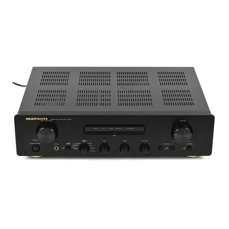
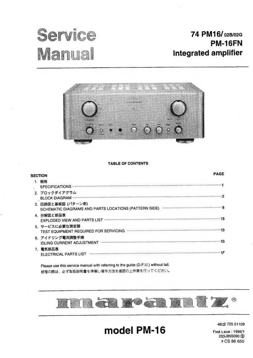
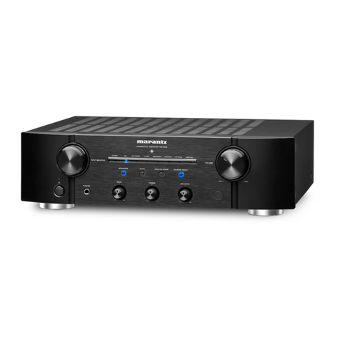
Marantz PM140 User manual

ae.
i
sae
:
ee
S
a
be
coe
ZEN
: ;
Cee
ce
AMIN
PYN
eS
oy,
(ee
2
Wx
SG
whe
Senn.
Cth
Sine
YA
[Shennan
weeren
Dees
:
eo
NAS:
ook
‘
AVN
2

MARANTZ
DESIGN
AND
SERVICE
Using
superior
design
and
selected
high
grade
components,
MARANTZ
company
has
created
the
ultimate
in
stereo
sound.
Only
original
MARANTZ
parts
can
insure
that
your
MARANTZ
product
will
continue
to
perform’‘to
the
specifications
for
which
it
is
famous.
Parts
for
your
MARANTZ
equipment
are
generally
available
to
our
National
Marantz
Subsidiary
or
Agent.
ORDERING
PARTS:
Parts
can
be
ordered
either
by
mail
or
by
telex.
In
both
cases,
MARANTZ
part
number
has
to
be
specified.
If
you
order
by
mail,
fulfil
MARANTZ
order
forms.
MARANTZ
S.A.
EUROPEAN
PARTS
DEPARTMENT
2,
Avenue
Léopold
III!
B-7120
PERONNES-lez-BINCHE
BELGIUM
TWX:
57589
SEPLT
B
The
following
information
must
be
supplied
to
eliminate
delays
in
processing
your
order:
Complete
address
Complete
part
numbers
and
quantities
required
Description
of
parts
Model
number
for
which
part
is
required
Way
of
shipment
Signature:
any
order
form
or
telex
must
be
signed
otherwise
such
part
order
will
be
considered
as
null
and
void.
amhon>
PARTS
ORDERING:
Parts
may
be
ordered
from
the
following
addresses:
EUROPE
MARANTZ
S.A.
MARANTZ
DENMARK
MARANTZ
BELGIUM
MARANTZ
NEDERLAND
B.V.
European
Parts
Department
Bregnergdvej
132b
45
Rue
Auguste
Van
Zande
Wagenmackersweg
3
2,
Avenue
Léopold
Iii
3460
Birkergd
1080
Brussels
3449
H.V.Woerden
B-7120
Péronnes-lez-Binche
Denmark
Belgium
Netherlands
Belgium
Telex:
39137
Telex:
57589
MARANTZ
S.A.
MARANTZ
FRANCE
MARANTZ
SVENSKA
A.B.
MARANTZ
ITALIANA
S.p.A.
326
Avenue
Louise
Bte
32
4
Rue
Bernard
Palissy
Svartviksvagen
56
Via
Monte
Napoleone,
10
1050
Bruxelles
92600
Asniéres
Traneberg
Bromma
20121
Milano
Belgium
France
Sweden
Italia
Telex:
26602
Telex:
611651
Telex:
13449
MARANTZ
GERMANY
G.M.B.H.
MARANTZ
AUDIO
U.K.
LTD.
MARANTZ
AUSTRIA
Ge.M.B.H.
Max-Planckstrasse
22
Unit
15/16
25
Franz
Lisztgasse
6072
Dreieich
1
Saxon
Way
Industrial
Estate
2380
Perchtoldsdorf
Germany
Moor
Lane
Austria
Telex:
4185316
Harmondsworth
UB7
OLW
Telex:
113583
Great
Britain
Telex:
935196
AUSTRALIA
MARANTZ
AUSTRALIA
PTY.,
LTD.
19
Chard
Road
Brookvale,
NSW
2100
Australia
Telex:
24121
All
of
the
above
locations
are
fully
equipped
to
take
care
of
your
total
service
needs.
Because
various
countries
have
differing
configuration
requirements,
it
is
necessary
that
you
contact
the
service
facility
in
your
particular
country.
In
the
event
that
there
is
no
service
location
listed
for
your
country,
please,
contact
the
nearest
facility
for
the
necessary
assistance.
In
case
of
difficulties,
do
not
hesitate
to
contact
the
Technical
Department
at
abovementioned
address.
ER
en
Been
eRe
ZZ’

MODEL
PM140
STEREO
CONSOLE
AMPLIFIER
TABLE
OF
CONTENTS
SECTION
PAGE
INTRODUCTION,
3-24
eis
aed
etinn
PE
Sa
is
SESE
ORO
ee
Rg
Bae
BE
ES
ee
eae
1
A
PAW.
BOARDS®
3.5
soups
c's
tis:
ot
Wie
Wale
Sie
Rk
Soe
Sis
whe
ie
Skene
bead
als
heed
ae
ee
pandas
1
2.
TEST
EQUIPMENT
REQUIRED
FOR
SERVICING
..............
2c
cece
eee
ee
eee
eee
1
3.:
IBEOCK.
DIAGRAM
°
25.22
ea
de
dictne
bh
Sod
ads
ate
Ree
A
DE
eee
a
eae
dais
aes
2
4.
VOLTAGE
CONVERSION
....
cee
eee
eee
eee
2
5.
TECHNICAL
SPECIFICATIONS
............
0.
cece
cee
cece
cece
cee
eee
seen
eeneeuags
3
6.
SCHEMATIC
DIAGRAM
AND
COMPONENT
LOCATIONS
................0-
000 eee
enee
4
6.1
Main
Amp.
Assembly
(P700)
Schematic
Diagram
and
Component
Locations
.............00000000085
4
6.2
Head
Phone
Jack
Assembly
(PWO0)
Schematic
Diagram
and
Component
Locations...
...........00+85
4
6.3.
Volume/Tone/Lamp.
Assembly
(PE00)
Schematic
Diagram
and
Component
Locations
.............005
5
6.4
Power
Switch
Assembly
(PG00)
Schematic
Diagram
and
Component
Locations
.............0..00085
7
7.
EXPLODED
VIEW
AND
PARTS
LIST
.....
ec
ce
en
nen
e
eens
8
S>
ELECTRICAL:
PARTS
(LAIST
sso
tetera
en
ie
aes
Ed
BEES
De
wi
IE
BE
i
10
9.
SCHEMATIC
DIAGRAM
..
6.
ccc
eee
eee
eee
ee
teen
e
eens
12

INTRODUCTION
This
service
manual
was
prepared
for
use
by
Authorized
Warranty
Staions
and
contains
service
information
for
the
Marantz
Model
PM140
Stereo
Console
Amplifier.
Servicing
information
and
voltage
data
included
in
this
manual
are
intended
for
use
by
knowledgeable
and
ex-
perienced
personnel
only.
All
instructions
should
be
read
carefully.
No
attempt
should
be
made
to
proceed
without
a
good
understanding
of
circuitry
operation.
The
parts
fist
furnishes
complete
ordering
information.
Most
replacement
parts
should
be
ordered
from
the
Marantz
Company.
However,
a
simple
description
is
in-
cluded
for
parts
which
can
be
obtained
locally.
1.
P.W.
BOARDS
As
can
be
seen
from
the
circuit
diagram
the
chassis
of
Mode!
PM140
consists
of
the
following
units.
Each
unit
mounted
on
a
printed
circuit
board
is
described
within
the
square
enclosed
by
a
bold
dotted
line
on
the
circuit
diagram.
1.
MainAmp.
........
mounted
on
P.W.
Board
P700
2.
Volume/Tone/Lamp.
..
mounted
on
P.W.
Board
PEOO
3.
Power
switch
.......
mounted
on
P.W.
Board
PGOO
4.
Head
Phone
Jack
....
mounted
on
P.W.
Board
PW00
2.
TEST
EQUIPMENT
REQUIRED
FOR
SERVICING
i
=
Item
Use
Distortion
Analyzer
Audio
Oscillator
ACVTVM
Oscilloscope
Circuit
Tester
Distortion
measurements
Sinewave
and
squarewave
signal
source
Voltage
measurements
(AC)
Waveform
analysis
and
trouble
shooting
and
ASO
alignment
Trouble
shooting
I
DC
VTVM
Voltage
measurements
(DC)
AC
Wattmeter
Monitors
primary
power
to
amplifier
Line
Voltmeter
Variable
Autotransformer
(0
~
140V
AC,
10A)
Adjust
level
of
primery
power
to
amplifier
Shorting
Plug
1.
The
secondary
winding
of
the
power
transformer
has
special
AC
power
outputs
for
the
power
supply
units
of
the
tuner
and
tape
deck.
2.
The
ON/OFF
switching
of
the
speakers
uses
the
head-
phones
jack
rather
than
a
manual
switch.
3.
Since
this
unit
uses
an
idling
non-adjustment
circuit,
when
replacing
the
parts,
be
sure
to
use
the
correct
idling
resistors
and
the
proper
rank
power
transistor
and
variable
resistors.
Monitors
potential
of
primary
power
to
amplifier
Shorts
amplifier
input
to
eliminate
noise
pickup
|

3.
BLOCK
DIAGRAM
PHONO
_AMP
MAIN
BALANCE
PHONO
VOLUME
VOLUME
.
POWER
TUNER
ran
SUPPLY
AUX
©)
TAPE
IN
TAPE
OUT
}
BASS
TREBLE
4.
VOLTAGE
CONVERSION
@
EUROPEAN
MODEL
ONLY
To
convert
the
unit
to
a
different
power
source
voltage,
change
the
position
as
illustrated
in
the
drawing
below.
CAUTION
DISCONNECT
POWER
SUPPLY
CORD FROM
AC
15V
-160mA
To
TUNER
(SV
400mA
To
DECK
SPEAKER
TERMINAL
PHONE
JACK
OUTLET
BEFORE
CONVERTING
VOLTAGE.
Voltage
Conversion
Chart
VOLTAGE
SELECTOR
120V
~
110V
~
Note
on
safety:
Symbol
A\
Fire
or
electrical
shock
hazard.
Only
orignal
parts
should
be
used
to
replace
any
part
marked
with
symbol
A
.
Any
other
component
substitution
(other
than
original
type),
may
increase
risk
of
fire
or
electrical
shock
hazard.
5.
TECHNICAL
SPECIFICATIONS
POWER
OUTPUT
PER
CHANNEL
DIN:8:
OHMS.
Tk
2)
6:3 i.5
sanded
ee
ates
he
dere
ae
Bale
&
eee
Ona
ei
a
ie
ew
6
Soe
alec
33W
RMS'S:
OHMS
VKH
Z:
ei
toe-d
ised
seb
ee
eh
ae
gd
ORGIES
end:
&
88
AR) bel
Sa
be
eS
Soe
eae
ek
30
W
TOTAL
HARMONIC
DISTORTION
AT
RMS
8
OHMS
...........
0.02
eee
ee ee
et
eee
eee
0.05%
Signal-to-Noise
Ratio
(IHF-A
Network)
PRU
sock
og,
Seetide
Base
BN
Gh
she
oat
Sai
eae
ht
ag
pica
are
Mook
tee
ec
ge
a
Me
we
Bae
hee
wees
Bek
Wetec
af
Panes,
he
ha
Sh
ee
aes
90
dB
Dimensions
(Wx
AixiD)
<x.
ok
ein
oS
eR
we
oe
ee
bo
ena
oe
baa
eek
ak
ae
416
x
80
x
200
mm
WIGHT
js
ecncsridtice
Sretatre
tet
Bite
Saha
as
Bat
ol
we
AS
eR
Bh
Ae
A
Oh
aba
ee
ees
4.2
kg

6.
SCHEMATIC
DIAGRAM
AND
COMPONENT
LOCATIONS
6.1
Main
Amp.
Assembly
(P700)
Schematic
Diagram
and
Component
Locations
ern
tees
Schematic
Diagram
and
Component
Locations
|
|
Pwoo
a
P700
es
705
409
3300p
==
Call.
0.012
MAIN
/PHONO/
POWER
SUPPLY
Pot
Ss
at
ce
56.1V
701
593.5
mV,
R7O!
Ik
3.3/50V
194,2mV
10
Ke
J703)
194.2m
f
3
R409.
22k
Rall
270k
[
"
te
=|
~360TV
O
C0540"
rh
5.27
mV
O
le al
Q40l
1/72
ig
|
R725
4.7
(1W)
O
cbc7is
a
I
QNO3
O
c4l3
0.033
Ol
x2!
;
+
+
~—$
3.3/50V
R415.
270
(BW)
|
|
5
+H
-05emvi
|
RNO|
RNOS
L701
1yH
5
a
as:
ais
R727
o72s
R703
ai
599,90
—
S220
oP
osaV:
6
ra
3403
:
680k
AR7o9
22
Cee
SS
&B
aM
O—-O-—
Wr
-
RNO3
25.05V
Me
4i7k
i
ES
c709
weer
R72t
56k
‘
Qnos
SRNO?
0.068"7~
+}47/50V
|477/16V
C7ISME
CTI7e
1$2472
J402
3.3/50V
|
3.3/50V
oO
ae
+
F
QNo6
O
C7TiI¢
Ze
crise
4
po
re
ee
|
chia
rea
av
i6y
R722
56k
3.3/50v[
33
/50v|+
is2a72
nate
gree
3.3/
50V
416
270
=
eer
—O
:
R
bryan
~
36.12V
NOS
25.09)
ts
602.77
=122mv
i)
C402
ics
04
XK)
a
eS
3:3./50V
7
O40!
1/2
C726
RTO4|
o7
~L24mv
(2)
220p
56k
:
RNOG
L702
1pH
R410
22k
R412
270k
150
NO4
4
4}~——
7
R726
|
C410
33000
C42.
0.012
e7eas
i
aoe
eaOl
4.7
Ww)
+
T
i
inh
r
we
a
L
T
2
el
E
ie
bt
"4
L
QNII
QNI5
= ,
aa
ZLARNI2
10
RNID
100
O-
-
36.28V
+4,
6.3
Volume/Tone/Lamp.
Assembly
(PE00)
Bhiode
tenor
Ie
a
pelematic
Diagram
and
Component
Locations
477
50N
36
gay
RNIB.
27k
fo)
oe
r
A
i?
5
:
1
QNIO
ANA
10k
-———
ySoigy
RNIZ
ai
Teves,
|
PEOO
ne
boo
si
a
VOLUME
/
32)
sv
fe
6
|
TONE
/LAMP
es
eer
oa
eee
Balance
aoe
role
seu
=
k
3.3/50V
Icso4
C$03
6
RBO3
Ik
(IW)
cscs
cs03
i
ic
A
bros
AQ80!
ssoi-2
bpd
e
ae
‘i
my
sos
“cao?
805
J+
:
68
C802
0.039
HZ(2-2
7
}OOMIBN
ggoa
45v1
0.01
Bs
A
Cw)
sls
|
i
2
8
a
RS08
=
RSO5
a
cs
RSO7
|
{
150
12k
_
150
Monitor
Loundness
Sa
SSO!
-
|
C804.
¢803
106
/16ve—
2200/
35V
ceolgye
10
/50v
3
ol
oon
oo
6.2
Head
Phone
Jack
Assembly
(PW00)
=
|
Sus
100k
ee
PHONO
JACK
oy
36
Rw5!
gs
f
330
(IW)
®
oo
x
=
CEIO
O1
£
aga
Jw52
xe
5 R
se
eo
eu
Gk
RW52
fu
330
(IW)
ws
oe
Phono
Tuner
Aux
Tape
Loudness
———————
Monitor

SET
CENTER
6.4
Power
Switch
Assembly
(PG00)
Schematic
Diagram
and
Component
Locations
[Ee
YK259H144-0.
R14
Zz
oe
R618
VV
TAPE
MON

7.
EXPLODED
VIEW
AND
PARTS
LIST
|BaBanee2qeacucd+-—
259H248400
259H248010
444H270010
444H115010
444H270010
259H158010
259H158020
259H274010
51280308B0
259H056010
259H154010
259H154020
DESCRIPTION
Front
Panel
Assembly
Front
Panel
Button,
Selector
Spring,
Selector
Button
Button,
Power
Window,
Selector
Window,
Green
Reflector,
Lamp
B.H.
Tapped
Screw
B3x8
Buffer
Button
Knob,
Master
Volume
Knob,
Slide
Volume
NNW
|2NONSB
ANS
1
2
2
2
5
2
=
NNS@
ANN]
Hd
=
NOON
NN
=
~
259H104020
51280308B0
259H104030
135HO005010
51280308B0
5128030880
51280308B0
51280308B0
51280308B0
51280308B0
259H267010
259H104010
51280308B0
51280308B0
51780312B0
51780312B0
Y
J06001050
Retainer,
Headphone
B.H.
Tapped
Screw
Retainer
Clamper,
Earth
.
Tapped
Screw
.
Tapped
Screw
.
Tapped
Screw
.
Tapped
Screw
.
Tapped
Screw
.
Tapped
Screw
Heatsink
Retainer,
Heatsink
B.H.
Tapped
Screw
B.H.
Tapped
Screw
Fin
Neck
B.T.
Screw
Fin
Neck
B.T.
Screw
Jack
(5P)
(N):for
Europe
©(A):for
Australia
DESCRIPTION
SB
eB
ANNNANH
BA
=
Pe
KH
ANNNANH
HA
=
PART
NO.
|
259H257010
51260408U0
259H105010
258H057010
259H121010
51100308A9
52040408A0
51280308B0
51280308B0
51280308B0
51280308B0
2112265110
2911861140
2911861110
FS10080800
YJ08000290
Y¥
103010250
BY05080050
YP04000580
TS16801080
Lid,
Top
Cover
B.T.
Screw
Chassis
Leg
Link,
Power
Switch
B.H.M.
Screw
H.
Head
Bolt,
S.F
B.H.
Tapped
Screw
B.H.
Tapped
Screw
B.H.
Tapped
Screw
B.H.
Tapped
Screw
Indicator,
Serial
No.
Label,
Top
Cover
Label,
Bottom
Cover
Fuse,
800mA
250V
Jack,
Fuse
Holder
Terminal,
GND
Voltage
Selector
Plug,
AC
Inlet
Power
Transformer
259H851310
259H851320
9631000090
259H801010
259809010
9090808030
9526019060
9526019030
ZC01805010
2C02006020
O92F
™~
®@—O3IB
PACKING
@(N):for
Europe
©(A):for
Australia
PACKING
User
Manual
User
Manual,
Spec
Warranty
Card
Packing
Case
Cushion
Polyethylene
Sheet
Serial
No.
Card
Serial
No.
Card
A.C.
Power
Cord
A.C.
Power
Cord

8.
ELECTRICAL
PARTS
LIST
aa
eer
wrorew
e
ewBs
aw
eo
eae
eB
eB
we
ww
OS
eee
ee
ee
aeoam
ae
eee
oem
eae
eee
ee
ee
ee
YK259H1410
22Z259H8410
EA33505030
EA33505030
DF16182310
DF16182310
£A10701030
EA10701030
DF16332310
DF16332310
DF16123310
DF16123310
£A33505030
EA33505030
DK18103310
P700-MAIN
AMP
CIRCUIT
BOARD
P.W.
Board,
Main
Amp
P.W.
Board
Assembly
DESCRIPTION
P700-CAPACITORS
Elect
3.3
uF
Elect
3.3uF
Film
1800pF
Film
1800p
F
Elect
100uF
Etect
100uF
Film
3300pF
Film
3300pF
Film
0.012uF
Film
0.012uF
Elect
3.3
uF
Elect
3.3uF
Ceramic
0.01
uF
EA33505030
EA33505030
EA10505030
EA10505030
DD15150370
0D15150370
DD15101370
DD15101370
EA47605030
EA47605030
Elect
Elect
Elect
Elect
Ceramic
Ceramic
Ceramic
Ceramic
Elect
Elect
3.3uF
3.3uF
Tur
Tur
15pF
15pF
100pF
100pF
47uF
47
uF
EA47601630
EA47601630
DF16333310
DF16333310
EA33505030
EA33505030
EA33505030
EA33505030
DD10020370
DD10020370
~aa
eo
aso
eB
oe
eee
=e
3
ee
ee
ee
DF16683310
DF16683310
DK16221300
DK16221300
DK18103560
DK18103560
EA22803590
EA10701630
EB68804540
EB68804540
EA10701630
EA10701630
“aa
a
EA47603530
EA22701030
EA10605030
£A10605030
22
a
a
wo
oe
ee
oS
EA33505030
EA33505030
0K16331300
DK16331300
DF16393310
DF16393310
Elect
Elect
Film
Film
Elect
Elect
Elect
Elect
Ceramic
Ceramic
Film
Film
Ceramic
Ceramic
47
uF
47
pF
0.033
nF
0.033
uF
3.3uF
3.3uF
3.3uF
3.3uF
2pF
2pF
0.068uF
0.068uF
220pF
220pF
Ceramic
Ceramic
Elect
Elect
Elect
Elect
Elect
Elect
Elect
Elect
Elect
Elect
Elect
Elect
Ceramic
Ceramic
Film
Film
0.01
uF
0.01
uF
2200pnF
100uF
6800puF
6800uF
100uF
100uF
47
uF
220uF
10uF
10uF
3.3uF
3.3uF
330pF
330pF
0.039uF
0.039uF
410%
+10%
410%
+10%
410%
10%
+10%
+5%
+5%
+5%
+5%
+10%
£10%
50V
50V
10V
10V
50V
50V
50V
50V
50V
50V
50V
50V
16V
50V
50V
50V
50V
40.25pF
+0.25pF
£10%
+10%
+10%
+10%
£10%
+10%
£10%
+10%
35V
16V
45V
45V
16V
16V
35V
10V
50V
50V
50V
50V
10
1
1
1
1
1
1
1
1
1
1
1
1
re
ee
ee
ee
ee
=
re
ee ee
ee
_
ee
ee
ee
ee
ee)
2
eo em
woo
=
So
eo
2aeew
eee
eee
ewe
ere
ee
ee
ee
ed
ere
ee
re
ee
oa
ew
oem
wee
oa
a
ee
ee
ee)
oo
ey
GD05473140
GD05473140
GD05222140
GD05222140
GD05561140
GD05561140
GD05223140
GD05223140
GD05274140
GD05274140
GD05271140
GD05271140
GD05102140
GD05102140
GD05563140
GD05563140
GD05102140
GD05102140
GD05684140
GD05684140
RF05220140
RF05220140
GD05123140
GD05123140
GD05390140
GD05390140
GD05563140
GD05563140
BW10000090
BW10000090
GA05047010
GA05047010
GA05180020
GA05180020
GA05102010
GA05102010
GD05151140
GD05151140
GD05472140
GD05472140
GD05151140
GD05151140
GD05153140
GD05153140
GD05123140
GD05222140
RFO5100140
GDO05564140
GD05103140
GD05333140
GD05563140
GD05223140
GD05273140
GD05101140
GD05104140
GD05104140
GD05273140
GD05273140
GD05123140
e(N):for
Europe
@(A):for
Australia
[N
[Al
P700-RESISTORS
(All
Resistors
are
5%
and
“W)
47KQ
47KQ
2.2KQ2
2.2K
5602
5602
22K
22K
270KQ
270KQ2
2702
2702
1KQ
1KQ
56K
56KQ
1KQ
1K
680KQ
680KQ
22a,
Fusible
222,
Fusibie
12KQ
12KQ
392
392
56KQ
56KQ
0.12x2
+5%
3W,Compo.
0.12
x2
+5%
3W,Compo.
4.72
IW
4.72
1W
182
2w
182
2W
1KQ
iw
1KQ
iw
1502
1502
4.7KQ
47KQ
1502
1502
15K
15KQ
12KQ
2.2KQ
102,
Fusible
560KQ
OK
33KQ
56KQ.
22KQ2
27KQ
1002
100K22
100K
27KQ
27KQ
12KQ
@(N):for
Europe
@(A):for
Australia
ION
PART
NO.
DESCRIPTION
Ean
,
np
Rsos
|1|
1}
GD05123140
12K2
PE0O-VOL./TONE/LAMP
Rso7
|1|1/|
GD05151140
1502
CIRCUIT
BOARD
Rsosg
|1]
1
|
GDO5151140
1502
PEOO
|1]11YK259H1420]
P.W.
Board,
Vo!./Tone/Lamp
Rsog
|1{|1|
GD05151140
1502
1
|
1]
2z259H8420
|
P.W.
Board
Assembly
rsio
|1|1|Gp05151140
1502
Rs11
11]
1]
GD05151140
1502.
aces
PEQO-CAPACITORS
6706
SEMICONDUCTORS
2
~|4|4|
EA10605030
|
Elect
10uF
50V
0401
|4
H
0
CE04
Uf
Ge
IROO
BOE?
|
IE
NEMS
DD
ceos
|1|1|
DF16472310
|
Film
4700pF
+10%
ceos
|1|1|
DF16472310
|
Film
4700pF
110%
Aa701
|1|1|
Hc100
1
P
ee
ipapiaite
‘
eeeatat
ceo7
|1|1|
DF16183310
|
Film
0.018uF
+10%
ceos
|1|1|
DF16183310
|
Film
0.018uF
+10%
AQ703
|1)1|HT111352BO
|
Transistor
2SA1135(0O
or
Y)
:
.
ceog
|1|
1]
0F16104310
|
Film
O.1uF
410%
AQ704
|1/1)HT111352B0
|
Transistor
2SA1135(O
or
Y)
K
:
CE10
|1|
1}
DF16104310
|
Film
O.iuF
+10%
aa705
|1}1|H1T32665280|
Transistor
2SC2665(0
or
Y)
,
CE11
|11
1]
DF16273310
|
Film
0.027nF
+10%
AQ706
}|1{1
|
HT326652B0
|
Transistor
2SC2665(0
or
Y)
:
4
Foae:
sl’
Havoaoosnan
|
Sarees
Bai
CE12
1111]
DF16273310
|
Film
0.027nF
+10%
Q
]
a
708
|1|1|
HVvoo006080
|
Varistor
STV-3H
an
NEISTARS
Aago1
|1|1|
HD20008290
|
Diode
S4VB-20
(AI
Reaksturs
sre
%e
and
aN)
REO1
|1|
1]
GD05153140
15KQ
Aago2
|1
|
1|HD20009290
|
Diode
2SV-20
:
REO2
|1|
1|
GD05153140
15KQ
Aa803
|1|1|HD20009290
|
Diode
2SV-20
Aasos
|1|1|HC38515090
|
IC
NJM78M15
REOS
|
1) 1)
GD05104140
NO0Ks2
agos
|1|1|HD30009010
|
Zener
HZ12-2L
REOA
|
1
7.1.)
GOGO)
ICO
agog
|1|1|HD30009010
|
Zener
HZ12-2L
REQS:
(:;/9t
|
GDOB27
2110
2.7KO
REO6
|1{1|
GD05272140
2.7KO.
ONo3
|1/1|HT32785280
|
Transistor
2SC2785(J
or
H)
REO7
|
1
|
1)
GD05153140
TOK.
onoa
|1|1|
132785280
|
Transistor
2SC2785(J
or
H)
REOB
|
1)
1)
GD0S153140
15K
QNO5
|1
|
1]
HD20002210
|
Diode
182472
REOY
|
1}
1|
GD05272140
2.7KQ
anos
|1|1|HD20002210
|
Diode
1$2472
RE10
|
1)
1)
GD05272140
2.7KQ
anio
|1]|1|H1T327852B0
|
Transistor
|
2SC2785(J
or
H)
RE11
|
1)
1|
GD05681140
6802
N11
|1/1]|H7111752B0
|
Transistor
|
2SA1175(J
or
H)
RE12
|
1)
1)
GD0S681140
6802
ani2
|1|1|
732785280
|
Transistor
2SC2785(J
or
H)
REIS>
4).
|
eogeee
140
gia
QN13
|1
|
1
|
HD20022030
|
Diode
DSF-10C
REI
|
tai)
a
00a36
110
Soule
QN14
|1|1|HT327852B0
|
Transistor
2SC2785(J
or
H)
RE15
|
1) 1]
RSO1040320
100K2(C)
x
2,
Variable
QNn15
|1|1|HT111752B0
|
Transistor
2SA1175(J
or
H)
BEIG
(1)
14,
RsOTOsG320
SOOK
ONE)
x2;
Variable
RE51
|1|
1]
RMO1040830
100KQ(B)
x
2,
Variable
J402
|11|1
|
75062501PO
|
Jumper,
25mm
RE53
|
1/
1}
GD05222140
2.2K2
J403
|111|75062501PO
|
Jumper,
25mm
RE54
|1/
1|
GD05222140
2.2K0
J704
111}
YT03040230
Terminal,
Speaker
(4P)
vss1
PEOO-MISCELLANEOUS
2
1515]
1N10080610
|
Lamp
50mA_
8V
J801
|1|
1}
YPO6001050
|
Plug
(5P)
VS55
J803
11/4
Ys04001030
|
Jack,
Deck
Y
J04001030
Jack,
Tuner
PGOO-POWER
SWITCH
CIRCUIT
BOARD
JsO5_
[1]
1
|
YLO1010110
|
Terminal,
Earth
Lug
PGoo
|1/1|
YK259H1440|
P.W.
Board,
Power
Switch
Jso6.
1111]
YT02040470
|
Terminal,
RCA
Jack
(4P)
111)
ZZ259H8440
|
P.W.
Board
Assembly
Jso7_
1
YT02060180
|
Terminal,
RCA
Jack
(6P)
AGoo1
|1|1|
DK18103840|
Ceramic
Cap.
0.01uF
250V
SP04050270
|
Push
Switch
AS001
|
1]
1}
SPO1010730
|
Push
Switch,
Power
w701
|1|1|YU03120260
|
Jumper
Lead
(3P)
:
w702
|1|1
|
YU05120260
|
Jumper
Lead
(5P)
ae
eaane.
ees
w703
|
1
YU05120260
|
Jumper
Lead
(5P)
pwoo
|1|1|
YK259H1430|
P.W.
Board,
Headphone
Jack
wso1
|1 {1
|
Yu06100260
|
Jumper
Lead
(6P)
Wh Ri
Ee
2BAR
ASO.
|
che
PORE
Pay
WS02
}1
|
1
|
YU07120260
|
Jumper
Lead
(7P}
Rws1
11111
GA05331010}
Resistor
3302
45%
1W
RW52
11/11
GA05331010
|
Resistor
3302
+5%
1W
JW52
|
111]
YJ01001770
Jack,
Headphone
NOTE
ON
SAFETY:
Symbol
A\
Fire
or
electrical
shock
hazard.
Only
original
parts
should
be
used
to
replace
any
part
marked
with
symbol
A,
Any
other
component
substitution
(other
than
original
type),
may
increase
risk
of
fire
or
electrical
shock
hazard.
(W01-99)
Assembly
and
Wiring
(T01-99)
Adjustment
(X01-00)
Correction

9.
SCHEMATIC
DIAGRAM
P700
MAIN
/
PHONO/
POWER
SUPPLY
C409
3300p
C4it
0.012
¢701
R70OI
Ik
3.3750V
R409
22k
R4il
270k
Q4oi
172
c40l
R405
R415
270
+)
orC709
wr
c7il
+147/50V
[477
16V
UEC7IO
BECTIi2
47/50V
AP
cI8N,
ik
R416
270
Q401
1/2
R412
270k
R410
22k
|
aan
C410
3300p
c4i2
0.012
807
Lo
TAPE
IN
RE
VOLUME/
TONE/LAMP)
L
TAPE
OUT
Ro
0.0047
2
wso:
—_—
N
O
us05
GND
TERMINAL
Jo3!
100k
(C)s.
100k
(C)
To
VR
EARTH
(REI5,REI6,
RES!, RES2Y
Loudness
Phono
Tuner
Aux
Tape
Monitor
Components
and
wiring
are
subject
to
change
for
modification
without
notice.
12
Model
PM140
A
PWwoOo
36.25V
Q705
s6.1v
QNII,
ONIS
HTI1752B0
s7034w70
awa
PHONO
JACK
2SAlI75
U
330
(Iw)
5.27
mv
O
ry
O
O
ples
vil
[ol
He
oe
oH]
Hope
|
L
9806
nna
7
aws2
HC38515090
CIOs
J
O
R
NJM78MI5
Pie
|
RWw52
330
(Iw)
Q707,Q708
HVO00006080
STV
-
3H(0)
J704
SPEAKER
Q4ol
QNO5,
QNOG
HC10008090
HD20002210
NJM45580D
1S2472
Q701,
Q702
QNI3
HC
10097060
HD
20022030
uPCI270H
DSFIOC
Q703,Q704
Q802
,Q803
ass
HT111352B0
:
HD20009290
4
2SA1135(Oory
s2v20
i
To
DECK
Q705
,Q706
Q808,Q809
od
i:
HT
32665280
HD30009010
J
Y
-
LO)
a
TUNES
28C2665
(Oor
HZ12
-
2b
QNO3
,QNO4
Q8ol
ONIO,QNI2,QNI4
HD20008290
HT327852B0
S4VB
-
20
2S8C2785
RNI6
56k
RNIG_
27k
FRONT
VIEW
pPCl270H
E
E
2SC
2665
2SA1135
|
c
8
4.
C803
2200/35V
6)
aay
et
O-aea8
A.
Q806
wAC
19.58V
Sy,
858
S
:
|
yor
oT]
O
O
A
(PEE
i
Ca
wise
PARTS
(N,T,A)
Laois
500000!
sooz
¢
Sig,
is
7
E
é
OUTPUT
:
NUM78MI5
8
B
E
E
TOP
VIEW
\
2sc2785
2SAlI75
NJM45580D
NOTE
ON
SAFETY:
Symbol
A\
Fire
or
electrical
shock
hazard.
Only
orignal
parts
should
be
used
to
replace
any
part
marked
with
symbol
Z\.
Any
other
component
substitution
(other
than
original
type),
may
increase
risk
of
fire
or
electrical
shock
hazard.
13
Table of contents
Other Marantz Amplifier manuals

Marantz
Marantz PM6004 User manual

Marantz
Marantz MR2020 User manual

Marantz
Marantz PM6010OSE User manual

Marantz
Marantz PM310 User manual

Marantz
Marantz PM5003 User manual

Marantz
Marantz SC-7S2 User manual

Marantz
Marantz SM-17SA User manual

Marantz
Marantz 240 User manual

Marantz
Marantz PM7001 User manual

Marantz
Marantz PM7001KI User manual

Marantz
Marantz SR7015 User manual

Marantz
Marantz 1070 User manual

Marantz
Marantz SR2100/N1S User manual

Marantz
Marantz MA-9S2 Use and maintenance manual

Marantz
Marantz Icemaker User manual

Marantz
Marantz MM8077 User manual
Marantz
Marantz SR7015 User manual

Marantz
Marantz MM7025 User manual

Marantz
Marantz PM5005 User manual

Marantz
Marantz 3650 User manual