Marantz LN7101F User manual

Anamorphic Lens System
®
Model LN7101F Installation Guide

2
The lightning flash with arrowhead,
within an equilateral triangle, is
intended to alert the user to the
presence of uninsulated “danger-
ous voltage” within the product’s
enclosure that may be of sufficient
magnitude to constitute a risk of
electric shock to persons.
1. Read these instructions.
2. Keep these instructions.
3. Heed all warnings.
4. Follow all instructions.
5. Do not use this apparatus near water.
6. Clean only with a dry cloth.
7. Do not block any ventilation openings. Install
in accordance with the manufacturer’s in-
structions.
8. Do not install near any heat sources such
as radiators, heat registers, stoves, or other
apparatus (including amplifiers) that produce
heat.
9. Do not defeat the safety purpose of the polar-
ized or grounding-type plug. A polarized plug
has two blades with one wider than the other.
A grounding type plug has two blades and a
third grounding prong. The wide blade or the
third prong are provided for your safety. If the
provided plug does not fit into your outlet,
consult an electrician for replacement of the
obsolete outlet.
10. Protect the power cord from being walked on
or pinched particularly at plugs, convenience
receptacles, and the point where they exit
from the apparatus.
The exclamation point within an
equilateral triangle is intended to
alert the user to the presence of im-
portant operating and maintenance
(servicing) instructions in the litera-
ture accompanying the appliance.
WARNING - TO REDUCE RISK OF
FIRE OR ELECTRICAL SHOCK, DO
NOT EXPOSE THIS EQUIPMENT TO
RAIN OR MOISTURE.
NO USER-SERVICEABLE PARTS
INSIDE. REFER SERVICING TO
QUALIFIED PERSONNEL.
To prevent the risk of electric shock, do not remove cover or
back. No user-serviceable parts inside.
IMPORTANT SAFETY
INSTRUCTIONS!
PLEASE READ THEM BEFORE
OPERATING THIS EQUIPMENT.
11. Only use attachments/accessories specified
by the manufacturer.
12. Use only with the cart, stand, tripod, bracket,
or table specified by the manu-
facturer, or sold with the appa-
ratus. When a cart is used, use
caution when moving the cart/ap-
paratus combination to avoid
injury from tip-over.
13. Unplug this apparatus during lightning storms
or when unused for long periods of time.
14. Refer all servicing to qualified service per-
sonnel. Servicing is required when the ap-
paratus has been damaged in any way, such
as power-supply cord or plug is damaged,
liquid has been spilled or objects have fallen
into the apparatus, the apparatus has been
exposed to rain or moisture, does not operate
normally, or has been dropped.
15. Do not expose this equipment to dripping or
splashing and ensure that no objects filled
with liquids, such as vases, are placed on the
equipment.
16. To completely disconnect this equipment from
the a.c. mains, disconnect the power supply
cord plug from the a.c. receptacle.
17. The mains plug of the power supply cord
shall remain readily operable.
18. Do not expose batteries to excessive heat
such as sunshine, fire or the like.

3
Technical Assistance
If at any time you have questions about your Marantz
product, contact your Marantz Dealer who is familiar
with your Marantz equipment and any other brands
that may be part of your system. If you or your Dealer
wish additional help concerning a suspected problem,
you can receive technical assistance for all Marantz
products at:
Marantz America, Inc.
100 Corporate Drive
Mahwah, N.J. 07430-2041
Tech & Operational Support hours:
9:00 AM to 5:00 PM ET, M-F
Tel. 800-654-6633 Toll Free
Tel. 201-762-6666
Fax. 201-762-6687 Parts
If it is determined that your Marantz product is in need
of repair, you can return it to your Dealer. You can
also return it to the Marantz Service Department. For
assistance on factory repair return procedure, contact
the Marantz at:
Marantz America, Inc.
100 Corporate Drive
Mahwah, N.J. 07430-2041
General Office hours:
8:30 AM to 5:30 PM ET, M-F
Tel. 201-762-6500
Fax. 201-762-6670
Copyright 2007 © by Marantz America, Inc.
ADDITIONAL SAFETY
INSTRUCTIONS!
WARNING:
THERE IS A POSSIBILITY OF SERIOUS
INJURY IF YOU DO NOT FOLLOW THESE
INSTRUCTIONS.
When mounting the projector to a building
structure, it is important to follow all of the local
building/construction codes. The total weight of
the Marantz VP-11, LN7101F Anamorphic Lens
System and MT20/EXT10 Mounting Brackets is
80 lbs (36.29 kg). Make sure the ceiling structural
members can support five times the total weight,
which is 400 lbs (181.44 kg).
Proper installation procedure by qualified
personnel as outlined in this installation guide is
required. It is recommended that the Profession-
als at your Marantz Dealer, who are skilled in all
aspects of installation and operation, install the
Marantz Video System and any associated audio
equipment.
It is important to read this LN7101F Installation
Guide and the VP-11 User Guide before starting
the installation process. The instructions in this
Installation Guide must be adhered to as failure
to do so could result in serious injury.
To prevent possible damage to the Lens As-
semblies, DO NOT at any time attempt to LIFT,
CARRY or RE-ORIENT the equipment using the
Lens.
A. Do not remove the cover from the equip-
ment.
B. Do not remove lens covers until instructed to
do so.
C. Do not insert anything into the equipment
through the ventilation holes.
D. Do not handle the mains lead with wet
hands.
E. No naked flame sources, such as lighted
candles, should be placed on the equipment.
F. Do not look into the lens when the projector
is turned on. It could damage your eyesight.
G. When disposing of used batteries, please
comply with governmental regulations or
environmental public instructions rules that
apply in your country or area.
Customer Service

4
5. To protect the lens surfaces from accidental dam-
age during the installation process DO NOT RE-
MOVE THE LENS COVERS UNTIL INSTRUCT-
ED.
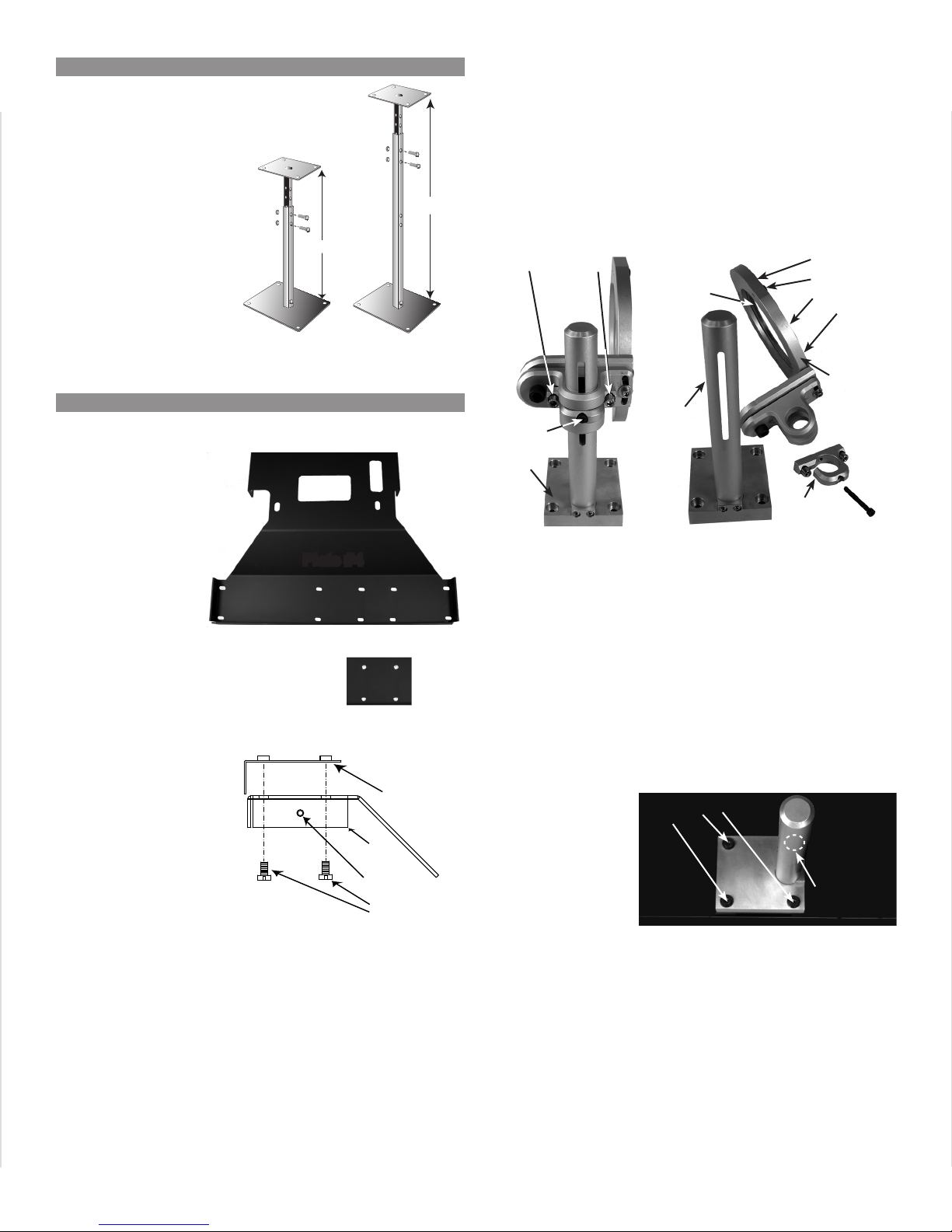
6. The assembly and adjustment of the LN7101F/
EXT10/MT20 will require a Phillips head screw
driver, adjustable wrench, 5/32 and 3/16 allen
tools.
7. When the symbol illustrated here
is located on the product or on the
packaging, it indicates the product
must not be disposed of with your
other household waste. Instead, it is
your responsibility to dispose of your
waste equipment by handing it over to a desig-
nated collection point for the recycling of waste
electrical and electronic equipment. The separate
collection and recycling of your waste equipment
at the time of disposal will help to conserve natural
resources and ensure that it is recycled in a man-
ner that protects human health and the environ-
ment. For more information about where you can
drop off your waste equipment for recycling, please
contact your local city office, your household waste
disposal service or the Marantz Dealer where you
purchased the product.
Important Information
Table of Contents
Safety Instructions ....................................................2
Thank You and Please Take a Moment ....................2
Technical Assistance and Customer Service ...........2
Table of Contents ......................................................3
Important, Connector and Cable Information ...........4
Dimensions ...............................................................5
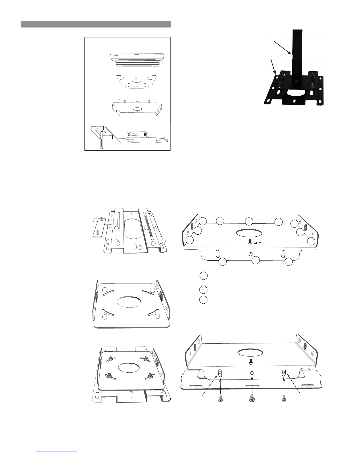
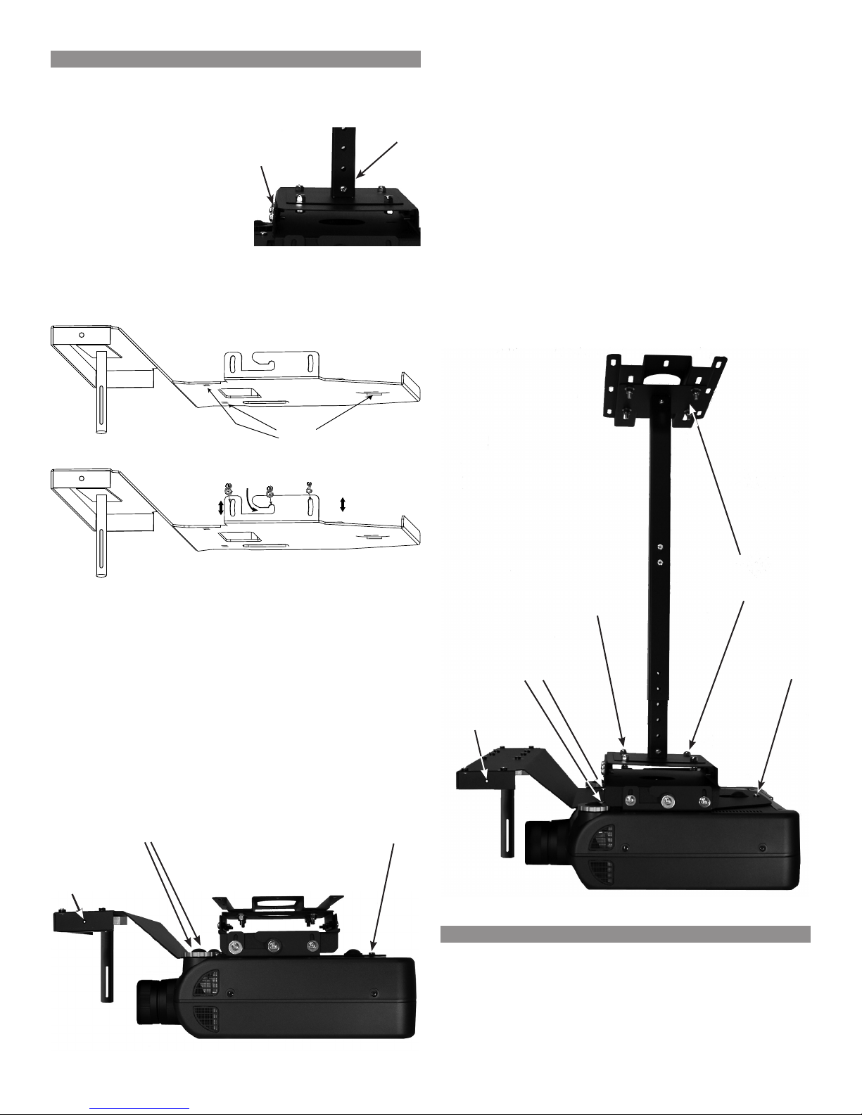
Installation Overview ................................................5
Installation ............................................................ 5-9
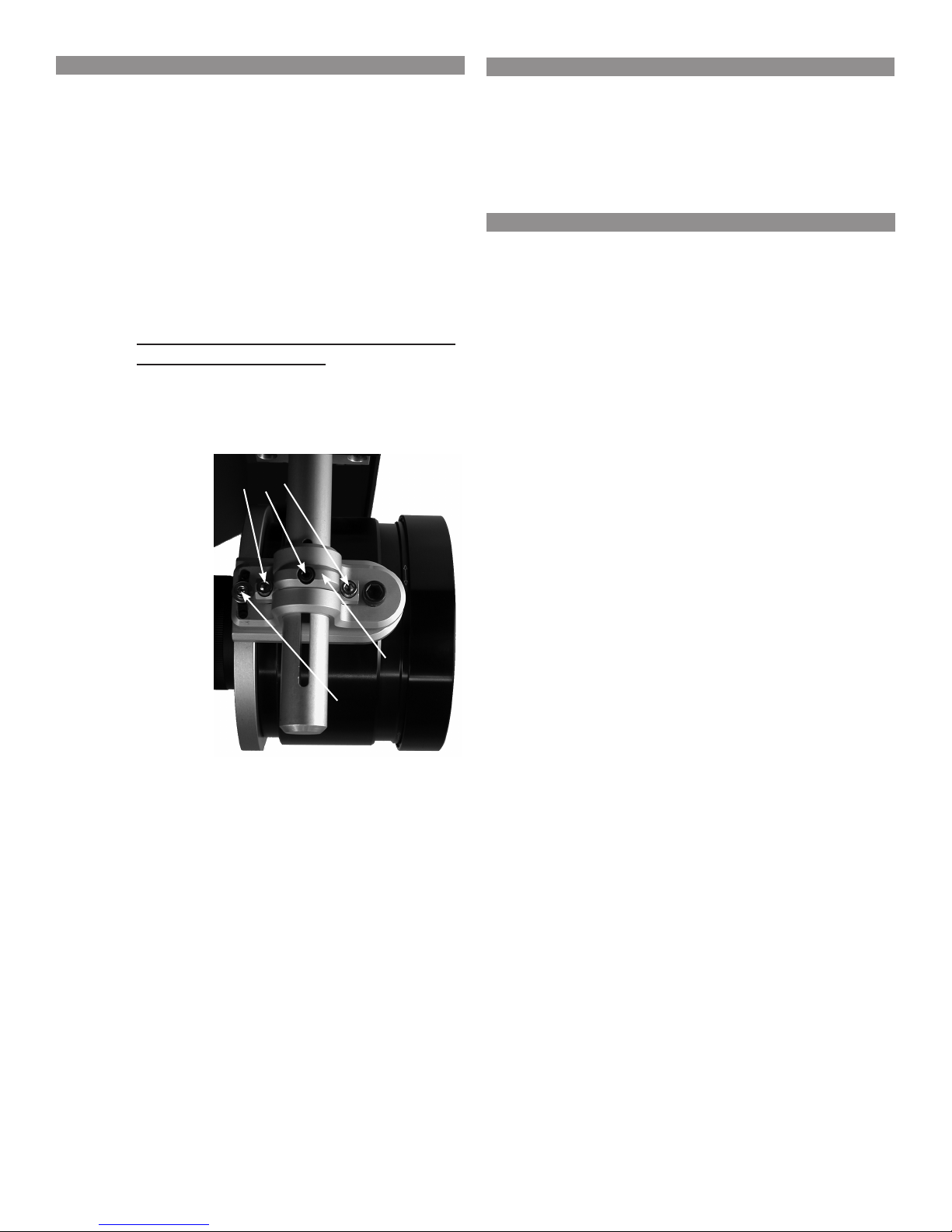
Alignment .................................................................9
Specifications .........................................................10
Warranty .................................................................11
CAUTION: The lenses contained in this product
are extremely delicate precision op-
tics, and may be scratched or other-
wise damaged by physical contact
with external objects of any kind. It is
therefore essential to avoid any such
contact, or any other mistreatment of
the lenses. Scratches or other exter-
nally caused damage to lenses that
are deemed to have arisen through
neglect or misuse, are excluded from
protection under the Marantz Limited
Warranty.
1. For additional connection information, refer to the
owner’s manual(s) for any component(s)) connect-
ed to the LN7101F Anamorphic Lens System.
2. The LN7101F Anamorphic Lens System (Fixed
Position) together with the Marantz VP-11 Projec-
tor will produce a full screen image when viewing
Anamorphic Source Material. It is not intended
to produce a full screen image when viewing
non Anamorphic Source Material. The Marantz
LN9101M Anamorphic Lens System (Two Position)
will produce a full screen image with either source
material. For additional information contact your
Marantz Dealer or Marantz.
3. The LN7101F Anamorphic Lens is designed to
produce the best possible images when a curved
Anamorphic Projection Screen is used, contact
your Marantz Dealer for additional information.
4. The Anamorphic Lens is a precision optical device
with special coatings just like you would find on
Professional Cameras. In the event the Lens re-
quires cleaning to remove airborne particles such
as dust and dirt from the Lens, use a safe cleaning
product such as a clean and dry 3MTM Scotch-
Brite® Microfiber Lens Cleaning Cloth. At no time
should ordinary household cleaning products be
used to clean the Lens, as damage will occur.

5
The LN7101F Anamorphic Lens System is designed
to mount together with the Marantz VP-11 onto the
ceiling of a typical room. Before choosing the location
on the ceiling, it is important to first read the “Installa-
tion” section of the VP-11 User Guide.
Some of the brackets from the Marantz MT20 (op-
tional ceiling mounting bracket) will be used to mount
the combination of the projector and LN7101F to the
ceiling. In some installations the EXT10 bracket will
also be used (optional extension pole kit).
This installation guide includes the assembly
instuctions from the MT20 and EXT10 Installation
Guides for easier installation. The LN7101F/MT20/
EXT10 were designed and manufactured to meet
strict quality and safety standards. There are however,
some installation and operation precautions which
you should be particularly aware of:
1. Read instructions - All the safety and operating
instructions should be read before the products are
used.
2. Retain instructions - The safety and operating in-
structions should be retained for future reference.
3. Heed warnings - All warnings on the products and
in the instructions should be adhered to.
4. Follow instructions - All installation instructions
should be followed.
5. Use only the parts provided with the mount, along
with any parts (commercially available) that are
specified in these instructions.
6. Do not modify the mount or the parts provided with
the MT20/EXT10/LN7101F.
7. Do not use damaged parts. If any parts become
damaged, contact your Marantz Dealer or Marantz.
8. All bolts and screws must be tightened securely
when instructed to do so.
9. After the projector mounting plate is attached to
the projector make sure not to block any additional
ventilation openings.
Dimensions
The following dimensions can assist in determining
the best
location
for the
combi-
nation
of the
Marantz
VP-11
and the
LN7101F
Anamor-
phic Lens System.
Installation Overview
10. Special techniques and experience are required
when installing the projector with the MT20/
EXT10/LN7101F. Contact your Marantz Dealer to
install the projector for you.
11. Once the projector is installed, periodic safety
checks of the rigidity of the MT20 Mounting Brack-
ets, EXT10 Extension Pole, LN7101F Anamorphic
Lens System and the VP-11 to the ceiling along
with secure fastening of all hardware should be
conducted on a regular basis.
EXT10 Assembly
After reading the “Installation” Section of the VP-11
User Guide and it has been determined the EXT10
Extension Pole will be needed to meet the require-
ments of location and ventilation for the Projector,
assemble the EXT10 by performing the steps below.
If the EXT10 will not be needed, proceed to the MT20
Assembly on page 7.
Note: The EXT10 hardware, fasteners and parts list
are located in a separate shipping carton from the
projector.
1. The EXT10 is adjustable from 43-3/4 inches to 24
inches as supplied. If the default range is accept-
able proceed to Step 3. The adjustable range may
be changed to 24 inches to 14-5/8 inches by cut-
ting both poles. When the installation requires the
24 inches to 14-5/8 inches range proceed to Step
2.
2. Cut the Outside
Pole to 13-3/8
inches from the
end the mount-
ing plate will be
attached. Cut
the Inside Pole
to 13-3/4 inches
from the end the
mounting plate
will be attached.
Refer to figure 1.
3. Attach the Bottom Mount-
ing Plate (the flange with
the wider space) to the
Outside Pole with two
Round Head Philips 1/4-20
x 3/8 Screws. In a similar
manner, attach the remain-
ing Plate to the Inside Pole. Refer to figure 2.
4. Assemble the Pole Pieces together making sure
to orient them as illustrated in figure 3 on the next
page.
Cut Here
Cut Here
Outside
Pole
Inside
Pole
13-3/8”
13-3/4”
Figure 1
Figure 2
21-15/16"
55.7cm
9-13/16"
24.9cm
20-1/16"
50.9cm

6
3. Locate the Lens Holder Assembly from the ship-
ping carton and orient it as shown in figure 7. Us-
ing the appropriate tool, loosen the two hex head
screws located either side of center on the Lock-
ing Ring. Remove the hex head screws, lift up on
the Lens holder and Locking Ring removing them
from the Post. Refer to figure 8.
Notes: Set aside the Lens, Lens Holder and Locking
Ring as they will be used after the VP-11 Pro-
jector/EXT10/MT20 have been installed and
initial setup adjustment have been made. The
actual Lens Holder Assembly is black in color.
The above illustrations are shown for purposes
of clarity.
4. Place the Lens Holder Base onto the Mount-
ing Plate 4 with the Lens Holder Post oriented
towards the outside edge of Plate 4. Secure the
Lens Holder Base with the four supplied 1/4-20x1
machine screws. Refer to figures 6 and 9.
5. Set aside the
just assembled
LN7101F/Plate
#4 for later use
and proceed to
the MT20 As-
sembly.
Assemble the LN7101F by performing the steps be-
low:
1. Locate Plate
#4 and the Top
Adjustment
Plate from the
LN7101F ship-
ping carton
and orient it as
shown. Refer to
figure 4 and 5.
Note: Plate #4
supplied
with the
MT20 Ceil-
ing Mount
Bracket Kit will
not be used.
2. Orient Plate 4 and
the Top Adjustment
Plate as illustrated in
figure 6. Secure the
two plates together
using four 1/4-20x1
socket head cap
screws, two at each
side and tighten
them with the sup-
plied Hex Wrench.
Set the Pole Pieces
to the desired length
and secure the posi-
tion using the two
Round Head Phil-
ips 1/4-20 x 2-1/4
Screws and two 1/4-
20 Lock Nuts. Refer
to figure 3.
5. Tighten all the re-
cently install hard-
ware and proceed
to assemble the
LN7101F.
14-5/8” to 24”
24” to 43-3/4”
Figure 3
EXT10 Assembly, con’t
LN7101F Assembly
Figure 9
Mounting screw
locations
Mounting
screw
location is
behind post
Plate #4
Top
Adjustment
Plate
Screws
1/4-20
tapped hole
Figure 6
Side View
Figure 5
Top Adjustment
Plate
Figure 4
Plate #4
Lens Holder Assembly
Figure 7
Loosen screws
Remove
screw
Base
Figure 8
Post
with
base
Lens
holder
Locking
Ring
Lens
alignment
collar
Alignment
collar
locking
screws

7
3. Install the combined
Plates #1 and #2 (or
Plate 1 with the EXT10)
securely to the Building
Structure following all of
the Local Building/Con-
struction Codes. Use
suitable hardware in ad-
equate quantity and size
depending on the installa-
tion requirements.
Caution: The Projector
together with the mounting brackets
weighs 80 pounds (36.29 kg).
4. Attach the Horizontal Tilting Plate #3 to the previ-
ously combined plates (already installed on ceiling)
using the 1/4-20 inch screws provided. Refer to
Figures 15 and 16. Install two 1/4-20inch screws
with rubber spacers and metal washers part way
into the welded metal studs (indicated #1). The
newly combined Plate 3 provides 10 degrees of
horizontal tilt. After positioning the plate, loosely
tighten the screws.
Assemble the MT20 by performing the steps below,
refer to figure 10:
Notes: The MT20 hardware, fasteners, mounting tem-
plate and parts list are located in a separate
shipping carton from the projector. Plate #4
supplied with the LN7101F will be used instead
of the MT20 Plate #4.
1. Insert Base Plate
connectors #1 into
the lateral position-
ing slots #3 from the
underside of Plate 1.
The lateral position-
ing slots will give
you 2-1/4 inches of
lateral adjustment for
projector alignment.
Refer to figure 11.
2. Base plate connector
holes #3 provide 15
degrees of horizontal
rotation adjustment.
Attach horizontal
adjustment Plate 2 to
the projector mount
ceiling Plate 1 using
the four (4) 5/16-18
inch nuts and wash-
ers provided. Refer
to figures 12 and 13.
Note: When the
EXT10 Exten-
sion Pole will
be used, attach
the “Outside
Pole” end to
Plate #1 (instead of Plate #2) using four (4)
5/16-18 inch nuts and washers provided. Refer
to figure 14.
MT20 Assembly
Figure 11
1
233
4
2
Base Plate Connectors #1
Projector Mount Ceiling Plate 1
Plate 1
2
Ceiling Wire
Access 4
Figure 12
3
33
3
Wire
Access
Plate 2
Figure 13
Wire
Access
Plates 1 & 2
Figure 14
EXT10
Plate #1
Figure 16
Plate 3
Tilting
Capability
Tilting
Capability
MB20 and LK1 Mounting Plates
Plate 1
Plate 4 (LN7101F)
Plate 2
Plate 3
Projector Side
Ceiling Side
Figure 10
MT20 and LN7101F Mounting Plates
Figure 15
Wire
Access
11
2
2
2
2
22
2
2
3
3
Plate 3
Holes for 1/4-20 inch screws
Holes for 1/4-20 inch screws with
rubber washer and steel washer
Indicates Forward
Positioning of Mount
1
2
3

8
Before installing the LN7101F Lens perform step 1
below:
1. It is very important to complete the Initial Instal-
lation and Setup of the VP-11 Projector before
installing the Lens. Refer to the User Guide of the
VP-11 Projector and perform the necessary proce-
dures.
Note: When the EXT10 Extension Pole will be used,
attach the “Inner Pole” end to Plate #3 (instead
of Plate #2) using four (4) 5/16-18 inch nuts and
washers provided.
Refer to figure 17.
6. Invert the projector and
place it on a soft, flat sur-
face. Align the three 6mm
mounting holes on the
projector with the mount-
ing holes on Plate #4 and
the LN7101F. Secure the bracket to the projector
using the three 6mm screws. Refer to figures 18
and 19.
Caution: The Projector together with the mount-
ing brackets weighs 80 pounds (36.29
kg). It requires two or more persons to
safely complete assembly.
Lift and slide the projector onto the 1/4-20 inch
screws previously installed in the metal studs of
the plate on the ceiling (see arrow in Figure 19).
Tighten the 1/4-20 inch screws on both sides of
the mount and install four 1/4-20 inch screws and
washers into the side of the projector Mounting
Plate 4. Refer to figure 20 (or figure 21 when the
EXT10 is used).
MT20 Assembly, con’t
Figure 17
EXT10
Plate #3
Projector Side
100Tilt 100Tilt
Ceiling Side
Figure 19
mounting
holes
Figure 18
LN7101F Lens Installation
Note: For added horizontal stability 1/4-20 eye bolts
may be screwed into either side of plate 4 with
guide wires attached to the eye bolts. Refer
to figures 20 and 21. For safety, the MT20/
EXT10 is designed to support the weight of the
LN7101F and VP-11 Projector without assis-
tance from the eye bolts with guide wire.
7. Before the LN7101F Lens can be installed and
adjusted, it is important to first complete the Instal-
lation and Initial Settings of the VP-11 Projector.
Refer to the User Guide of the VP-11 Projector
and perform the necessary procedures. When the
Installation and Initial Settings of the projector is
complete, proceed to the LN7101F Lens Installa-
tion.
Figure 20
Ceiling
6mm screws 6mm screw
1/4-20
tapped
hole
Figure 21
Ceiling
6mm screws 6mm screw
Hex head
bolts and lock
nuts (supplied
with EXT10)
EXT10
Extension
Pole Kit
1/4-20
tapped
hole

9
After having performed the Initial Installation and
Setup of the VP-11 Projector, the LN7101F Lens can
be installed by performing the following steps:
2. Locate the previously
set aside LN7101F
Lens and place it on
a flat surface oriented
with the small Lens
Cover facing up. Refer
to figure 22.
3. Carefully remove the
small cover from the
Lens by screwing it
counterclockwise, it
will take multiple turns.
Place the removed
cover in a safe place for possible future use.
4. The inner circumference of the Lens Holder is
threaded to accept
the Lens. It is ex-
tremely important
not to cross thread
the Lens or Lens
Holder when start-
ing the fastening
process and do not
over tighten. Refer to
figure 23.
5. Orient the Lens Holder/Lens over the end of Lens
Holder Mounting Post as illustrated in figures 24
and 25. Lower the Lens Holder/Lens onto the
top of the post and insert the previously removed
Locking Ring in-between the two ring type parts of
the Lens Holder as it is lowered onto the post.
Figure 22
Small Lens Cover
Figure 23
Lens Holder
Mounting Post
Figure 24 Figure 25
Locking
Ring
Figure 27
Large Lens
Cover
Figure 26
Tighten Screws
Insert Screw
and Tighten
Locking
Ring
LN7101F Lens Alignment
Perform the following steps to align the LN7101F Lens
to the projector:
1. Switch On the projector and activate the built in
crosshatch test pattern.
2. Verify the horizontal center of the LN7101F Lens
coincides with the horizontal center of the projector
Lens. If the LN7101F Lens doesn’t line up, loosen
the screws on the LN7101F Lens Holder Base and
slide the Top Adjustment Plate slightly to the left or
right relative to Plate 4 to center the Lens. Tighten
the screws. Refer to figures 4, 5 and 6 on page 6.
6. While holding
the Lens Hold-
er/Lens about
two inches from
the top on the
Lens Holder
Post, insert
the previously
removed screw
into the center
of the Lock-
ing Ring and
tighten. Also
tighten the other
two screws
located either
side of the
center screw on
the Lock Ring.
Refer to figure
26.
Note: At this
time, do
not be
overly
con-
cerned
about the
exact po-
sition of
the Lens.
The final
Lens po-
sition will
be set
during the Lens Alignment procedure.
7. Remove the large Lens Cover from the front of the
Lens by grasping both sides of the cover and pull-
ing straight forward. Refer to figure 27.
8. Proceed to “ LN7101F Lens Alignment”.

10
Notes: The projected test pattern will probably have
some forms of geometric distortions as a result
of misalignment of the Anamorphic Lens to the
projector.
3. If the Test Pattern appears tilted on the screen
loosen the four locking screws on the Lens align-
ment collar and rotate the Lens to straighten the
pattern. Then tighten the four locking screws.
Refer to figure 8 on page 6.
Notes: Inside the Lens close to the front are two
vertical visible black masks. When the edge of
those masks are parallel with the Lens Holder
Post, the crosshatch should no longer be tilted.
Do not look directly into the Lens, look off
from the side at an angle.
4. Rotate the front part of the LN7101F Lens for the
best focus.
5. Using the appropriate tools loosen the three
screws on the Lens Holder Locking Ring while at
the same time
supporting the
Lens on the
bottom. Refer to
figure 28.
6. Adjust the
height of the
LN7101F Lens
so its vertical
center coincides
with the center
of the projec-
tor lens and the
crosshatch pat-
tern is centered
vertically on the
screen. Tighten the center screw on the Locking
Ring and then rotate the LN7101F Lens left to right
to center the crosshatch pattern horizontally on
the screen. Then tighten the two screws previously
loosened on the Locking Ring.
7. The final adjustment is to straighten the lines of the
crosshatch test patern. Loosen the tilt adjustment
screw located near the Lens Holder. The front of
the LN7101F Lens can be pivoted up or down to
straighten the lines in the test pattern. Then tighten
the screw to retain the position.
Note: If the screen used is not a curved anamorphic
screen, some geometric distortion may be visible.
8. Proceed to Operation.
LN7101F Lens Alignment, con’t
Figure 28
Locking Ring
Screws
Tilt
Adjustment
Screw
Locking
Ring
Operation
Change the Aspect Ratio setting on the Marantz VP-
11 Projector by performing the following step:
1. Switch On the projector and press the ASPECT
Ratio Push-button until the “V-STRETCH” Mode is
selected using the Projector’s Remote Control.
Specifications
Lens
1.33x (2.35:1 Cinemascope)
Operating Temperature and Humidity
41 to 95oF (5 to 35oC), 30 to 85%
Overall Dimensions including Projector
Width is 20-1/16 inches (50.9cm)
Height is 9-13/16 inches (24.9cm)
Depth is 21-15/16 inches (55.7cm)
Weight
23 pounds (10.4 kg) net, 36 pounds (16.3 kg) in shipping
carton

®
For U. S. A.
Limited Warranty
Marantz America, Inc. (“Marantz”) warrants the
following Marantz Products for the periods indicated:
1. The following Marantz Audio/Video components, have a 3 year
warranty for both Parts & Labor, from the original purchase date:
Amplifiers, Pre Amplifiers, Pre Amplifier-Processor- Tuners,
Integrated Amplifiers, Tuners, Receivers, DVD Players,
CD-Recorders, CD Players, Audio Cassette Decks, Learning
Remote Control Devices, Universal Dock & DLP Front
Projectors.
2. Plasma Display Devices have a 3 year warranty for labor, 2 years
on parts and 1 year on the Panel from the original purchase date.
3. Anamorphic Lens System have a 2 year warranty for parts and
labor from the original purchase date.
4. DLP lamps have a 90 day warranty for parts and labor from the
original purchase date.
What is covered and what is not covered
Except as specified below, this warranty covers parts and labor to
correct all defects in materials and workmanship. The following are
not covered by the warranty:
1. Damage, deterioration, malfunction or failure to meet performance
specifications resulting from:
a) Accident, acts of nature, misuse, abuse, neglect or
unauthorized product modification.
b) Improper installation, removal or maintenance, or failure to
follow instructions supplied with the product.
c) Repair or attempted repair by anyone not authorized by
Marantz to repair the product.
d) Any shipment of the product (claims must be presented to the
carrier).
e) Any cause other than a product defect.
2. Cleaning, initial set-up, check-ups with no defects found, or charges
incurred for installation, removal or reinstallation of the product.
3. Any product on which the serial number has been defaced, modified
or removed.
4. Batteries.
5. Accessories, including but not limited to, batteries, cables, mounting
hardware and brackets, cleaning accessories, antenna and detachable
power cords.
6. Warranty is void if purchase was made from any one other than an
authorized Marantz dealer.
Who may enforce the warranty
This warranty may be enforced only by the original purchaser.
What we will pay for
We will pay for all labor and material expenses for items covered by
the warranty. Payment of shipping charges is discussed in the next
section of this warranty.
How you can get service
1. If your unit needs service, contact Marantz service referral by
calling toll-free 1-800-654-6633. We will advise you of the name
and location of one or more authorized Marantz service stations
from which service can be obtained. Please do not return your unit
to the factory without prior authorization.
2. You must pay any shipping charged if it is necessary to ship the
product for service. However, if the necessary repairs are covered
under warranty, we will pay the return shipping charges to any
destination within the United States, its possessions or territories.
3. Whenever warranty service is required, you must present the
original dated sales receipt or other proof of date of purchase.
Limitation of implied warranties
All implied warranties, including warranties of merchantability and
fitness for a particular purchase, are limited in duration to the length of
this warranty.
Exclusion of damages
Marantz liability for any defective product is limited to repair or
replacement of the product at Marantz’s option. Marantz shall not be
liable for damage to other products caused by any defects in Marantz
products, damages based upon inconvenience or loss of use of the
product, or any other damages, whether incidental, consequential, or
otherwise.
How state law relates to the warranty
Some states do not allow limitations on how long an implied warranty
lasts and/or do not allow the exclusion or limitation of incidental or
consequential damages, so the above limitations or exclusions may not
apply to you.
This warranty gives you specific legal rights, and you may also have
other rights which vary from state to state.
Marantz America, Inc.
100 Corporate Drive
Mahwah, N.J. 07430-2041
Phone. 800-654-6633 Fax. 201-762-6695

www. marantz.com
You can find your nearest authorized distributor or dealer on our website.
U. S. A. Marantz America, Inc. 100 Corporate Drive, Mahwah, NJ 07430, U. S. A.
®
is a registered trademark.
Printed in U. S. A. Part No. 04104200 07/2007
Table of contents
Other Marantz Projector Accessories manuals