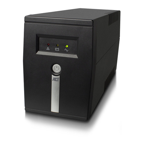
Marathon Power vault series Operating instructions

9DXOW6HULHV
7UXH2Q/LQH
'RXEOH&RQYHUVLRQ
8QLQWHUUXSWLEOH3RZHU6XSSO\
86(50$ 8$/
)2502'(/6
9$9$

2

Table of Contents
Section Page
1.
Introduction ............................................................................................................................. 7
2.
System Description ................................................................................................................. 7
2.1
General Description…………………………………………………………………………………7
2.2
System Configuration……………………………………………………………………………….8
3.
Safety Information ................................................................................................................... 9
4.
Storage ..................................................................................................................................... 9
5.
Installation ............................................................................................................................. 10
5.1
Environment ...................................................................................................................... 10
5.2
AC Power and Load Connection ........................................................................................ 10
5.3
Rear Panel Views .............................................................................................................. 16
5.3.a
Tower Models - 4k / 5kVA Rear Panel Views……………………………………………16
5.3.b
Tower Models - 6kVA Rear Panel Views .................................................................... 17
5.3.c
Tower Models 8k / 10kVA Rear Panel Views ............................................................. 18
5.3.d
Tower Models12kVA Rear Panel View ....................................................................... 19
5.3.e
Tower Models 15k / 20kVA Rear Panel Views ........................................................... 20
5.3.f
Rack Mount Models 4k / 5k / 6k / 8k / 10k /12kVA Rear Panel Views ............................. 21
5.4
Connecting an Extended Run-Time battery Pack .............................................................. 22
5.5
Factory Default Settings .................................................................................................... 22
6.
Communication Interface and Alarm Connections ........................................................ 22
6.1
Overview ........................................................................................................................... 22
6.2
Connecting the UPS to a Computer .................................................................................. 22
6.3
RS-232 Interface Port ........................................................................................................ 23
6.4
USB Port ........................................................................................................................... 23
6.5
EPO (Emergency Power Off) Port ..................................................................................... 23
6.6
Network Transient Protector .............................................................................................. 23
6.7
Load Segments ................................................................................................................. 23
7.
Operational Instructions ....................................................................................................... 24
7.1
Starting Up and Shutting Down the UPS. .......................................................................... 24
7.2
Push-button Operations .................................................................................................... 24
7.3
Control Panel Indicators .................................................................................................... 25
7.4
LCD Panel Display Modes ................................................................................................. 26
7.5
Manual UPS or Battery Test .......................................................................................................... 27
7.6
Sense Mode – Normal and Generator Waveforms…………………………………………..28
7.7
Audible Alarms .................................................................................................................. 28
7.8
Troubleshooting ................................................................................................................ 29
8.
Maintenance ........................................................................................................................... 30
8.1
Battery Replacement ......................................................................................................... 30
9.
Specifications ........................................................................................................................ 31
10.
Warranties ............................................................................................................................ 34
3

(0&6WDWHPHQWV
&,635
27,&( 3XUVXDQW WR &,635 UXOHV WKLV SURGXFW KDV EHHQ WHVWHG DQG WKHUHE\ FRPSOLHV
ZLWK WKH FRQGLWLRQV RI D &ODVV GLJLWDO GHYLFH ZKLFK KDYH EHHQ HVWDEOLVKHG IRU RIIHULQJ
VXI¿FLHQW SURWHFWLRQ DJDLQVW GDQJHURXV LQWHUIHUHQFH IRU LQVWDOODWLRQ LQ D UHVLGHQWLDO DUHD
,QVWDOODWLRQ DQG XVH RI WKH HTXLSPHQW VKRXOG FRPSO\ ZLWK WKH LQVWUXFWLRQV SURYLGHG LQ RUGHU
WR DYRLG VXFK LQWHUIHUHQFH GXH WR WKH DPRXQW RI UDGLR IUHTXHQF\ HQHUJ\ WKDW LV UDGLDWHG DQG
JHQHUDWHG E\ WKH HTXLSPHQW ,Q VSLWH RI WKLV ZH FDQQRW DVVXUH WKDW D FHUWDLQ DPRXQW RI
LQWHUIHUHQFH PD\ QRW RFFXU LQ VRPH LQVWDOODWLRQV ,I E\ WXUQLQJ RQ DQG RII LW FDQ EH GHGXFHG
WKDW \RXU UDGLR RU WHOHYLVLRQ UHFHSWLRQ LV IRXQG WR EH LQÀXHQFHG E\ KDUPIXO LQWHUIHUHQFH
IURP WKH HTXLSPHQW LW LV UHFRPPHQGHG WR XVH RQH RI WKH IROORZLQJ SUHYHQWLYH PHDVXUHV
3ODFHWKHUHFHLYLQJDQWHQQDLQDVHSDUDWHORFDWLRQRURULHQWDWLRQ
(QVXUHDJUHDWHUGLVWDQFHLVDFKLHYHGEHWZHHQWKHUHFHLYHUDQGWKHHTXLSPHQW
(QVXUHWKDW\RXUHTXLSPHQWLVFRQQHFWHGWRDQRXWOHWRQDVHSDUDWHFLUFXLWWKDQWKHUHFHLYHU
&RQWDFWDWHFKQLFLDQH[SHULHQFHGZLWKUDGLRDQG79RUDGHDOHUIRUIXUWKHUDVVLVWDQFH
'HFODUDWLRQRI&RQIRUPLW\5HTXHVW
8QLWVODEHOHGZLWKD&(PDUNFRPSO\ZLWKWKHIROORZLQJVWDQGDUGVDQGGLUHFWLYHV
1. Harmonic Standards: EN 50091-1-1 and EN 50091-2
2. EU Directives: 73/23/EEC, Council Directive on equipment designed for use within
certain voltage limits.
93/68/EEC, Amending Directive and 73/23/EEC
89/336/EEC, Council Directive relating to electromagnetic compatibility
92/31/EEC, Amending Directive 89/336/EEC relating to EMC
The EC Declaration of Conformity is available upon request for products with a CE mark.
4

IMPORTANT SAFETY INSTRUCTIONS
SAVE THESE INSTRUCTIONS
1.
This Manual Contains Important Instructions that should be followed during Installation and
Maintenance of the UPS and Batteries.
2.
CAUTION (UPS with Internal Batteries): Risk of electric shock - Hazardous live parts inside
this unit are energized from the battery supply even when the input AC power is disconnected.
3.
CAUTION (No User Serviceable Parts): Risk of electric shock, do not remove cover. No user
serviceable parts inside. Refer servicing to qualified service personnel.
4.
CAUTION (Non-isolated Battery Supply): Risk of electric shock, battery circuit is not isolated
from AC input / output; hazardous voltage may exist between battery terminals and ground.
Test before touching.
5.
WARNING (Fuses): To reduce the risk of fire, replace only with the same type and rating of
fuse.
6.
WARNING: Intended for installation in a controlled environment. The maximum ambient
temperature is 40°C.
7.
CAUTION: Do not open or damage the battery, electrolyte may be released which is harmful
to the skin and eyes.
8.
CAUTION: A battery can present a risk of electric shock and high short circuit current. The
following precautions should be taken when working with batteries:
a.
Remove watches, rings and other jewelry or metal objects.
b.
Use only tools with insulated handles.
c.
Wear rubber gloves and boots.
d.
Do not lay tools or metal parts on top of batteries.
e.
Disconnect charging source prior to connecting or disconnecting battery terminals.
9.
Do not dispose of batteries in a fire, as they may explode.
10.
To reduce the risk of electric shock, disconnect the UPS from the AC input power supply
before installing a communication interface cable. Reconnect the power cord only after
communication interconnections have been made.
11.
Battery replacement should be performed or supervised by personnel with knowledge of
batteries. Keep unauthorized personnel away from the batteries.
12.
CAUTION: To reduce risk of fire, connect only to a circuit provided with 2pole 70A maximum
branch circuit over current protection in accordance with the National Electric Code,
ANSI/NFPA 70". An AC output disconnect shall be provided by others.
5

7KHLQVWUXFWLRQVFRQWDLQHGZLWKLQWKLVVDIHW\PDQXDODUHH[WUHPHO\LPSRUWDQWDQGVKRXOGEHFORVHO\
IROORZHGDWDOOWLPHVGXULQJLQVWDOODWLRQDQGIROORZXSPDLQWHQDQFHRIWKH836DQGEDWWHU\
)RUDGGLWLRQDOVDIHW\LQVWUXFWLRQVSOHDVHXVHWKH6DIHW\0DQXDODVUHIHUHQFH
6\PEROV
7KHIROORZLQJV\PEROVZDUQRISUHFDXWLRQVDQGSURYLGHGLUHFWLRQVRULQVWUXFWLRQUHJDUGLQJWKHXQLW
5,6.2)(/(&75,&6+2&.±,QGLFDWHVWKDWWKHUHLVDULVNRIHOHFWULFVKRFN
& 87,215()(57223(5 725¶60 18 /±,QGLFDWHVWKDWWKHRSHUDWRU¶VPDQXDO
VKRXOG EH UHIHUUHG WR IRU DGGLWLRQDO LQIRUPDWLRQ VXFK DV RSHUDWLQJ DQG PDLQWHQDQFH
LQVWUXFWLRQV
6 )(*5281',1*7(50,1 /,QGLFDWHVSULPDU\VDIHJURXQG
/2 '212))±,QGLFDWHVWKDWWKHDVVRFLDWHGSXVKEXWWRQWXUQVWKHXQLWDQGLWVRXWSXW
RQRURII
5- &211(&725 ± ,QGLFDWHV WKDW WKLV FRQQHFWRU SURYLGHV QHWZRUN LQWHUIDFH
FRQQHFWLRQV DQG WKDW WHOHSKRQH RU WHOHFRPPXQLFDWLRQV HTXLSPHQW VKRXOG 127 EH
SOXJJHGLQWRLW
',6326 / ± ,QGLFDWHV WKDW WKH 836 DQG LWV EDWWHULHV VKRXOG EH GLVSRVHG RI LQ WKH
FRUUHFWPDQQHUVLQFHWKHEDWWHULHVDUHRIWKHOHDGDFLGW\SH,WLVUHFRPPHQGHGWKDWWKH
EDWWHULHVEHUHF\FOHG
&$87,2
7KHXQLWFRQWDLQVGDQJHURXVYROWDJHOHYHOV,IWKH836LVRQEXWQRWFRQQHFWHGWR
DQ$&SRZHUVXSSO\WKHXQLW¶VRXWOHWVPD\VWLOOEHHQHUJL]HGZLWKYROWDJHGXHWRWKH
SUHVHQFHRIDQLQWHUQDOSRZHUVRXUFHLHWKHEDWWHU\
7KH XQLW VKRXOG EH LQVWDOOHG LQGRRUV LQ DQ DUHD IUHH RI HOHFWULFDOO\FRQGXFWLYH
FRQWDPLQDQWV
7KHXQLWVKRXOGEHLQVWDOOHGLQDWHPSHUDWXUHDQGKXPLGLW\FRQWUROOHGHQYLURQPHQWLQ
RUGHUWRUHGXFHWKHULVNRIHOHFWULFVKRFN
2QO\WKHSRZHUFRUGWKDWLVVXSSOLHGZLWKWKHXQLWVKRXOGEHXVHGWRFRQQHFWLWWRWKH
$&SRZHUVXSSO\7KHHTXLSPHQWVKRXOGDOVREHORFDWHGDVFORVHDVSRVVLEOHWRWKH
$&VXSSO\
6HUYLFLQJDQGPDLQWHQDQFHVKRXOGRQO\EHFDUULHGRXWE\TXDOL¿HGVHUYLFHSHUVRQQHO
ZLWKWKHH[FHSWLRQRIEDWWHU\UHSODFHPHQW
%HIRUHFDUU\LQJRXWEDWWHU\RUIXVHUHSODFHPHQWRUVKLSSLQJWKHXQLW¿UVWHQVXUHWKDW
WKHXQLWLVWXUQHGRIIFRPSOHWHO\DQGDOOFDEOHVDUHGLVFRQQHFWHG
6

,QWURGXFWLRQ
6\VWHP'HVFULSWLRQ
7KHLQIRUPDWLRQSURYLGHGLQWKLVPDQXDOUHIHUVWRRXUVLQJOHSKDVH9 WKURXJK9
WUXHRQOLQH XQLQWHUUXSWLEOHSRZHUVXSSOLHV,WFRYHUVEDVLFIXQFWLRQV RSHUDWLQJDQGLQVWDOODWLRQ
LQVWUXFWLRQVFDXWLRQDU\QRWHVDQGGHWDLORQKRZWRVKLSVWRUHDQGKDQGOHWKHP,QVWDOODWLRQPXVW
EHFDUULHGRXWLQDFFRUGDQFHZLWKWKLVPDQXDODVZHOODVORFDOHOHFWULFDOUHJXODWLRQVDQGVKRXOG
RQO\EHSHUIRUPHGE\TXDOL¿HGSHUVRQQHOWRDYRLGWKHULVNRIHOHFWULFVKRFNRUGDPDJHWRWKHXQLW
Q\ZDUUDQWLHVFRYHULQJWKHVHXQLWVZLOOEHFRPHYRLGLIWKHXQLWLVIRXQGWRKDYHEHHQLQFRUUHFWO\
FRQQHFWHGRUWDPSHUHGZLWK
*HQHUDOGHVFULSWLRQ
&RQ¿JXUHGDVDWUXHRQOLQHGRXEOHFRQYHUVLRQXQLWWKLV836LVDEOHWRVXSSO\VHDPOHVVSXUH
VLQJOHSKDVH &SRZHUWRFULWLFDOORDGVZKLOHNHHSLQJWKHEDWWHULHVFKDUJHGFRQWLQXRXVO\,Q
WKHHYHQWWKDWDSRZHULQWHUUXSWLRQODVWVORQJHUWKDQWKH836¶VEDFNXSWLPHFDSDELOLW\LWZLOO
VKXWGRZQWRDYRLGFRPSOHWHEDWWHU\GLVFKDUJH VVRRQDV &SRZHULVUHVWRUHGWKH836ZLOO
DXWRPDWLFDOO\UHVWDUWDQGEHJLQUHFKDUJLQJWKHEDWWHULHV
EORFNGLDJUDPRIWKH836LQIUDVWUXFWXUHLVVKRZQLQ)LJ
QLQSXW¿OWHUUHGXFHVWUDQVLHQWVQRLVHDQGVXUJHVRQWKHLQFRPLQJ &VXSSO\
&SRZHULVUHFWL¿HGDQGUHJXODWHGE\WKHUHFWL¿HUVXSSO\LQJSRZHUWRWKHLQYHUWHUDQGEDWWHU\
FRQYHUWHU%DWWHU\YROWDJHDQGFKDUJHLVPDLQWDLQHGDWRSWLPXPOHYHOV
'&SRZHULVFRQYHUWHGWR &SRZHUE\WKHLQYHUWHUZKLFKSDVVHVLWRQWRWKHORDG
3RZHULVVXSSOLHGIURPWKHEDWWHU\GXULQJDSRZHUIDLOXUHRUGHHSYROWDJHVDJ
7KHFRQYHUWHULQFUHDVHVYROWDJHWRDQDSSURSULDWHOHYHOIRUWKHLQYHUWHU
QLQWHJUDODXWRPDWLFE\SDVVVZLWFKVHDPOHVVO\FLUFXPYHQWVWKHHOHFWURQLFVLQWKHHYHQWRID
FRPSRQHQWIDLOXUHHQVXULQJFRQWLQXRXVSRZHUWRWKHORDG
)LOWHU 3)&
5HFWL¿HU ,QYHUWHU %\3DVV
6ZLWFK )LOWHU
0RQLWRULQJ
3DQHO
56RU
86%
6ORW
&KDUJHU
%DWWHU\
6ZLWFK
%DWWHU\
&RQWURO
0RQLWRULQJ
Fig. 1
7

(I¿FLHQF\2SWLPL]HU
7KH(I¿FLHQF\2SWLPL]HULVDXQLTXHIHDWXUHWKDWUHGXFHVORQJWHUPFRVWRIRZQHUVKLSE\PLQLPL]LQJSRZHU
ORVVDQGUHGXFLQJSRZHUFRQVXPSWLRQWKHUHE\PDNLQJWKHHQWLUHV\VWHPH[WUHPHO\HI¿FLHQW6LPSO\SXW
WKH836DXWRPDWLFDOO\DOWHUQDWHVEHWZHHQE\SDVVDQGRQOLQHPRGHVGHSHQGLQJXSRQWKHFRQGLWLRQRIWKH
LQFRPLQJ &SRZHU7KH836ZLOOUHPDLQLQRQOLQHPRGHGXULQJDQ\W\SHRISRZHUGLVWXUEDQFHEXWXQOLNH
WUDGLWLRQDORQOLQHV\VWHPVZLOOVZLWFKWRE\SDVVPRGHZKHQ &SRZHULVZLWKLQDFFHSWDEOHOLPLWVLQRUGHU
WRDFKLHYHJUHDWHVWHI¿FLHQF\3RZHUGLVWXUEDQFHVFDQEHGHWHFWHGLQOHVVWKDQDVHFRQGDQGRQOLQHPRGH
UHDFWLYDWHGLPPHGLDWHO\6ZLWFKLQJEDFNWRRQOLQHPRGHRFFXUVZKHQWKHLQSXWYROWDJHLVRXWVLGHRI
RIQRPLQDOVHOHFWDEOHZKHQLQSXWIUHTXHQF\LVRXWVLGHRI+]RUZKHQQR &SRZHULVSUHVHQ
W
:KLOHWKHGHIDXOWRSHUDWLRQLVRQOLQHPRGHE\SDVVFDQEHDFWLYDWHGYLDWKH/&'SDQHO7KH(I¿FLHQF\
2SWLPL]HUFDQEHGHDFWLYDWHGDQGWKHXQLWFDQEHUXQSHUPDQHQWO\LQRQOLQHPRGHLISUHIHUUHG
)UHH5XQ0RGH
)UHHUXQPRGHLVGH¿QHGDVEHLQJZKHQWKHRXWSXWIUHTXHQF\LV¿[HGDQGQRWV\QFKURQL]HGZLWK
WKHLQSXWIUHTXHQF\:KHQDFWLYDWHGWKHRXWSXWIUHTXHQF\UHJXODWLRQLVDXWRPDWLFDOO\VHWWRHLWKHU
RU+]DQGLVUHJXODWHGWRZLWKLQZLWKLQ+]3OHDVHUHIHUWR&KDSWHUIRULQVWUXFWLRQVRQ
KRZWRDFWLYDWHE\SDVVPRGHZKLOHWKH836LVLQIUHHUXQPRGH
'LDJQRVWLFWHVWV
:KHQHYHUWKH836LVWXUQHGRQDGLDJQRVWLFWHVWWRFKHFNWKHVWDWXVRIWKHLQWHUQDOHOHFWURQLFV
DQGEDWWHU\LVDFWLYDWHG Q\HUURUVRUIDXOWVDUHGLVSOD\HGRQWKH/&'SDQHO
QDGYDQFHGEDWWHU\PDQDJHPHQWV\VWHPFRQWLQXRXVO\PRQLWRUVWKHFRQGLWLRQRIWKHEDWWHULHV
DQGQRWL¿HVWKHXVHULQDGYDQFHLIUHSODFHPHQWLVQHHGHG
,QDGGLWLRQDEDWWHU\GLVFKDUJHWHVWLVSHUIRUPHGHYHU\GD\VLQQRUPDOPRGHRSHUDWLRQDQG
DQ\SUREOHPVDUHGLVSOD\HGRQWKH/&'SDQHO
'LDJQRVWLFWHVWVFDQEHSHUIRUPHGPDQXDOO\IURPWKH/&'SDQHODWDQ\WLPHH[FHSWGXULQJWKH
¿UVWKRXUVDIWHUVWDUWXSZKLOHWKH836LVLQFKDUJLQJPRGHVHH&KDSWHU
6\VWHP&RQ¿JXUDWLRQDQG6L]LQJ
7KHLQWHUQDOHOHFWURQLFVRIWKH836SOXVWKHLQWHUQDOEDWWHU\RUEDWWHULHVFRQVWLWXWHWKHV\VWHP
3OHDVHPDNHVXUHWKDWWKHIROORZLQJIDFWRUVKDYHEHHQWDNHQLQWRFRQVLGHUDWLRQ
7KHWRWDOGHPDQGRIWKHSURWHFWHGORDGGHWHUPLQHVWKH836SRZHU9 UHTXLUHPHQWV OORZ
VRPHPDUJLQRUKHDGURRPIRUIXWXUHH[SDQVLRQRUSRZHUUHTXLUHPHQWFDOFXODWLRQLQDFFXUDFLHV
VLGHIURPSRZHU9 UHTXLUHPHQWVEDFNXSWLPHQHHGVWREHFRQVLGHUHG,IWKHSRZHUFRQVXPHGE\
WKHORDGLVOHVVWKDQWKHQRPLQDOSRZHUUDWLQJRIWKH836WKHQWKHDFWXDOEDFNXSWLPHZLOOEHORQJHU
7KHIROORZLQJRSWLRQVDUHDYDLODEOHGHSHQGLQJRQDSSOLFDWLRQDQGORDGUHTXLUHPHQWV
D([WHUQDO%DWWHU\3DFNV(%3¶VIRUH[WHQGHGUXQWLPHV
E,QSXW2XWSXWWUDQVIRUPHUFDELQHWV
F0DLQWHQDQFHE\SDVVVZLWFKHV
G&RQQHFWLYLW\DQGFRQWURORSWLRQVHJUHOD\FDUG6103:(%FDUG
8

WARNING! It is strongly advised that the UPS NOT be opened by anyone
other than suitably qualified personnel. Dangerously high voltages are
present within, regardless of whether the UPS is connected or not. In addition,
the unit's output receptacles may contain live AC voltage even when not connected to
the AC power supply since it contains its own energy source, (i.e. batteries).
3. Safety Information
PLEASE READ THIS SECTION TO AVOID RISK OF SHOCK OR
OTHER HAZARDOUS SITUATIONS.
1.
Please handle the unit with extreme caution since the batteries contain large amounts of
energy. Always store the unit in the orientation marked on the packaging.
2.
Take extra care to avoid dropping the unit.
3.
If flammable substances are present or if any gases or fumes are being emitted or if there is
no ventilation in the place of storage or installation, a safety hazard exists and neither the unit
or the extended battery packs should be operated in these environments.
4.
The instructions in this manual detail how to install the UPS safely and correctly. Please read
it thoroughly and keep this manual for future reference.
User Allowable Operations
The only UPS-related operations that the user is allowed to perform are:
1.
Turning the unit on and off.
2.
Operating the user interface (function push-buttons and LCD panel).
3.
Connecting data interface cables
4.
Changing the batteries
All such operations are to be performed exactly as instructed in this manual. Any deviation from
these instructions may prove hazardous and even fatal or may cause damage to the unit.
4. Storage
Please adhere to the following storage instructions if the UPS is not to be installed shortly after
delivery:
1.
Store the unit as is in its original packing and shipping container.
2.
Store the UPS covered, upright and in a cool, dry location, with its battery fully charged.
3.
Before storing, charge the UPS for at least 8 hours.
4.
Ensure that the equipment is fully protected from wet or damp areas and from moisture.
5.
Ensure that the UPS is recharged every 6 months for at least 8 hours in order to maintain
battery energy and maximize useable life.
6.
For temperature ranges, please refer to "Environmental Specifications" stated in this manual.
9

Ensure that all environmental requirements are met, otherwise the safety of installation
personnel and users cannot be guaranteed. In addition, the unit may sustain damage
or malfunction.
The high voltage and current contained within this equipment can injure or be fatal to
personnel and can damage associated equipment.
5. Installation
5.1
Environment
Please adhere to the following environmental instructions when locating the UPS and EBP's:
1.
Avoid temperature and humidity extremes. The optimum operating temperature range is
between 59°F and 77°F (+15°C and +25°C).
2.
Provide protection against moisture or avoid altogether if possible.
3.
Ensure there is at least 4 inches (100mm) behind and 2 inches (50mm) on each side of the
UPS for ventilation.
4.
Ensure that the front of the UPS remains unobstructed for access to the control panel and
LCD display.
5.
External Battery Packs must be installed next to or under the UPS.
5.2
AC Power and Load Connections
Vertical and Wall-Mount Installation
Only qualified technicians should carry out installation of this equipment. The installation must
further comply with all local legislation and regulations.
Follow all installation and safety instructions very carefully to avoid the existence of a hazardous
situation and damage to the UPS and/or loads.
Various input (and sometimes output) cables are supplied with all models:
1.
Ensure that the UPS is disconnected from the AC supply when connecting External Battery
Packs.
2.
Use the battery cable that is supplied with the External Battery Pack when connecting it to the
UPS. Connect the second battery cabinet to the first and so forth, assuming more than one is
to be used.
3.
Take note of UPS parameters when adding external battery packs and adjust accordingly
(see Ch. 7).
4.
Connect the input cable to the UPS and connect the other end to a grounded AC power
supply. The batteries will automatically begin to charge. Please note that while the UPS may
be used immediately, maximum back-up time may not be available until the batteries have
been charged for a minimum of 8 hours. See Table 1 for input circuit breaker rating and
conductor size.
5.
If the unit displays "Site Wiring Fault", have the wiring fault corrected or alternately, disable the
related alarm on the UPS.
6.
After initial charging is complete, connect the loads to the UPS.
7.
Do not connect any load that may overload the UPS such as equipment containing AC electric
motors or loads that have a high inrush current.
8.
Make computer and/or alarm interface connections according to Chapter 6 of this user manual
and that provided with the interface option. These connections are made on the rear panel.
9.
Installation is now complete.
10

Table 1
Additional Installation Information (for 6000VA ~ 20000VA Models)
1.
Ensure that all electrical connections have been correctly implemented for the installation site out.
2.
Refer to Table 2 for input and output breaker rating.
3.
Isolate and prevent the source from activating. Both input and output circuit breakers (located on
the rear of the unit) must be in the "OFF" position.
4.
Refer to figure 2 for single cable input connection and figure 3 for dual cable input connection. If
installing dual cables, the interconnection jumper (J) shown in figure 2 needs to be removed.
5.
If during installation, it cannot be determined that the neutral is grounded or identification
of the status of the neutral in the AC supply is unreliable, an additional two pole disconnect
device may be necessary in the for the installation.
6.
Should the optional Emergency Power Off (EPO) circuit on the rear on the unit be used, the
output of the UPS will shut down immediately.
Note: Local safety requirements may require a separate external Emergency Power Off that
opens output circuit breakers. Refer to local wiring regulations.
Table 2
Wire size
6-8 AWG
Wire Stripping length
8 mm
Minimum temperature
60 ℃
Wire conductor material
Copper only
Screw Torque
18 lb.-in
VGD 4K-12K, Tower UPS:
UPS Model Input Breaker Rating Output Breaker Rating Battery Breaker Rating
4KVA 1P, 277Vac, 20A 1P,125/250VAC,16A 1P,125/250VAC,10A NA
5KVA (bat*10) 1P, 250Vac, 30A 1P,125/250VAC,16A 1P,125/250VAC,10A NA
5KVA (bat*20) 2P, 250Vac, 30A 2P, 250Vac, 30A NA
6KVA 2P, 250Vac, 30A 2P, 250Vac, 30A NA
8KVA 2P, 250Vac, 63A NA 2P, 250Vac, 63A
10KVA 2P, 250Vac, 63A NA 2P, 250Vac, 63A
12KVA 2P, 250Vac, 63A NA 2P, 250Vac, 63A
VRM 4K-12K, Rack Mount UPS:
UPS Model Input Breaker Rating Output Breaker Rating Battery Breaker Rating
4KVA 1P, 277Vac, 20A NA NA
5KVA (bat*10) 1P, 250Vac, 30A NA NA
5KVA (bat*20) 2P, 250Vac, 30A 2P, 250Vac, 30A NA
6KVA 2P, 250Vac, 30A 2P, 250Vac, 30A NA
8KVA 1P, 250Vac, 65A 1P, 250Vac, 65A NA
10KVA 1P, 250Vac, 65A 1P, 250Vac, 65A NA
12KVA 1P, 250Vac, 65A 1P, 250Vac, 65A NA
11

Fig. 2
~
=
Static
Bypass
LNPE
LNPE
L
N
PE
J
L
N
PE
L
N
PE
Bypass
Input
Rectifier
Input
EPO
Circuit
Breaker
Input
Output
=
~
PFC &
Booster
Inverter
Battery
Static
Bypass
L1 N1 PELNPE
L2 N2 PE
L1
N1
PE
J
L2
N2
PE
L
N
PE
EPO
Input
PFC &
Booster Battery
Inverter
Output
~
==
~
Fig.3
Circuit
Breaker
Circuit
Breaker
12

9HUWLFDO,QVWDOODWLRQ :DOO0RXQW,QVWDOODWLRQ
9HUWLFDODQG:DOO0RXQW,QVWDOODWLRQ
7KH IROORZLQJ GLDJUDPV LOOXVWUDWH KRZ WR LQVWDOO RU PRXQW WKH 836 DQG EDWWHU\ SDFNV ZKHQ
DSSOLFDEOHLQHLWKHUYHUWLFDORUZDOOPRXQWDSSOLFDWLRQV
13

/RZHU6LGH5DLO,QVWDOODWLRQ 5HDU%UDFNHW,QVWDOODWLRQ
´5DFN0RXQW,QVWDOODWLRQ
7KH IROORZLQJ GLDJUDPV LOOXVWUDWH KRZ WR LQVWDOO RU PRXQW WKH 836 DQG EDWWHU\ SDFNV ZKHQ
DSSOLFDEOHLQ´UDFNPRXQWDSSOLFDWLRQV
14

6WDFN,QVWDOODWLRQ
8QLW6WDFN,QVWDOODWLRQ
7KHIROORZLQJGLDJUDPVLOOXVWUDWHKRZWRVWDFNWKHXQLWVDQGEDWWHU\SDFNVZKHQDSSOLFDEOH
15

5HDU3DQHO9LHZV
D7RZHU0RGHOVNN9$5HDU3DQHO9LHZV
97:(5HDU9LHZRU
97:(5HDU9LHZRU
'LIIHUHQWRXWSXWUHFHSWDFOH
RSWLRQVDYDLODEOH
N9$5($53$ (/
9()*,7\SH
5HDU9LHZ
N9$5($53$ (/
9,(&7\SH
5HDU9LHZ
N9$5($53$ (/
9 (0$7\SH
5HDU9LHZ
16

E7RZHU0RGHOVN9$5HDU3DQHO9LHZV
97:(5HDU9LHZRU
'LIIHUHQWRXWSXWUHFHSWDFOH
RSWLRQVDYDLODEOH
N9$5($53$ (/
ZLWKRXW,62
5HDU9LHZ
N9$5($53$ (/
ZLWK,62
5HDU9LHZ
17

F7RZHU0RGHOVNN9$5HDU3DQHO9LHZV
N9$5($53$ (/
ZLWK,62
5HDU9LHZ
N9$5($53$ (/
ZLWKRXW,62
5HDU9LHZ
97:(5HDU9LHZRU
97:(5HDU9LHZRU
'LIIHUHQWRXWSXWUHFHSWDFOH
RSWLRQVDYDLODEOH
18

G7RZHU0RGHOVN9$5HDU3DQHO9LHZV
.9$5($53$ (/
ZLWKRUZLWKRXW,62
5HDU9LHZ
97:(5HDU9LHZ
'LIIHUHQWRXWSXWUHFHSWDFOH
RSWLRQVDYDLODEOH
19

H7RZHU0RGHOVNN9$5HDU3DQHO9LHZV
97:(5HDU9LHZ
97:(5HDU9LHZ
'LIIHUHQWRXWSXWUHFHSWDFOH
RSWLRQVDYDLODEOH
.9$5($53$ (/
ZLWKRUZLWKRXW,62
5HDU9LHZ
20
Other manuals for vault series
3
This manual suits for next models
16
Table of contents
Other Marathon Power UPS manuals
Marathon Power
Marathon Power TRTC-2002-N1 User manual
Marathon Power
Marathon Power vault series User manual

Marathon Power
Marathon Power vault series User manual
Marathon Power
Marathon Power SNMP Series User manual

Marathon Power
Marathon Power Sprint Series User manual
Marathon Power
Marathon Power Tri-Athlon ATWS-10003-02 User manual
Marathon Power
Marathon Power TRTC-2004-N1 User manual

Marathon Power
Marathon Power SDRS-0300-H1 User manual
Marathon Power
Marathon Power Athlon SEries User manual
Marathon Power
Marathon Power Track Series User manual

