Marathon NetRunner 5000UG/130PS/S Instruction Manual

Part Number 800-1868-43, Rev
. A
Installing the Power Supply
into an Integration Unit
For Model 5000UG/130PS/S
This manual is for MICOM Certified Distributors only. The
procedure described here installs a power supply upgrade to
the integration unit. No power supply upgrades may be done
in the field.
WARNING:
This procedure must be done by a qualified technician.
This technician must be familiar with both the Integration
unit and power supplies.
!
February 1996

Notice of Filing
Declaration of CE Conformance (for International sales)
A Declaration of CE Conformance is on file at the MICOM addresses shown below. The declaration lists the
models described in this manual. If the unit carries the CE mark, this declaration certifies that it meets the
specific EMC standards required for CE marking. If the product is a module, the module is CEcompliant
only if it is placed in a MICOM CEmarked base unit.
MICOM Communications Corp.
4100 Los Angeles Avenue
Simi Valley, California 930633397
U.S.A.
(805) 5838600
MICOM Communications Corp. (Europe) Ltd.
The Granary
Grange Court
Grange Road
Tongham, Surrey GU10 1DW
England, UK
44 1252 781 777
Any units not carrying the CE approval are not CEcompliant. Modules placed in these units may not meet
emission standards for CE compliance.
Trademark Notice
MICOMr, Marathonr, NetRunnerr, FrameRunnert, STADIAt, NETMant,
rFEATUREPAK, FlashPakt,
tMicroBand ATM, Power Plust, SNAPSt,MICOMrBOX,
a
nd tValUMu
x a
re trademarks or
registered trademarks of MICOM Communications Corp. All other names or trademarks are the true
property of their respective companies.
Notice
Specifications, tolerances, and design characteristics (other than for regulatory requirements) described in
this manual are subject to change without notice.
E1996 MICOM Communications Corp.
All rights reserved
Unpublished rights reserved under the copyright laws of the United States
RESTRICTED RIGHTS LEGEND
Use, duplication, or disclosure by the Government is subject to restrictions as set forth in
subparagraph (c) (1) (ii) of the Rights in Technical Data and Computer Software clause at 252.2277013.

1
Installation
A Phillips head screw driver is required. A magnetic one might be beneficial.
Installing the Power Supply
There are seven tasks in the installation process: Details discussed
on page
1. Open the unit 2
2. Disconnect and remove the old power supply 3
3. Install and connect the new power supply 5
4. Install the cover 7
These steps are detailed on the following pages.
Note: There are two types of chassis, one which is CE approved (for European stan-
dards) and another, which does not carry the CE mark (meets domestic stan-
dards). They are basically the same except for cover removal/installation and
the way the spacers reside in the unit. Both units are illustrated.

Installing
the Power Supply into an Integration Unit
2
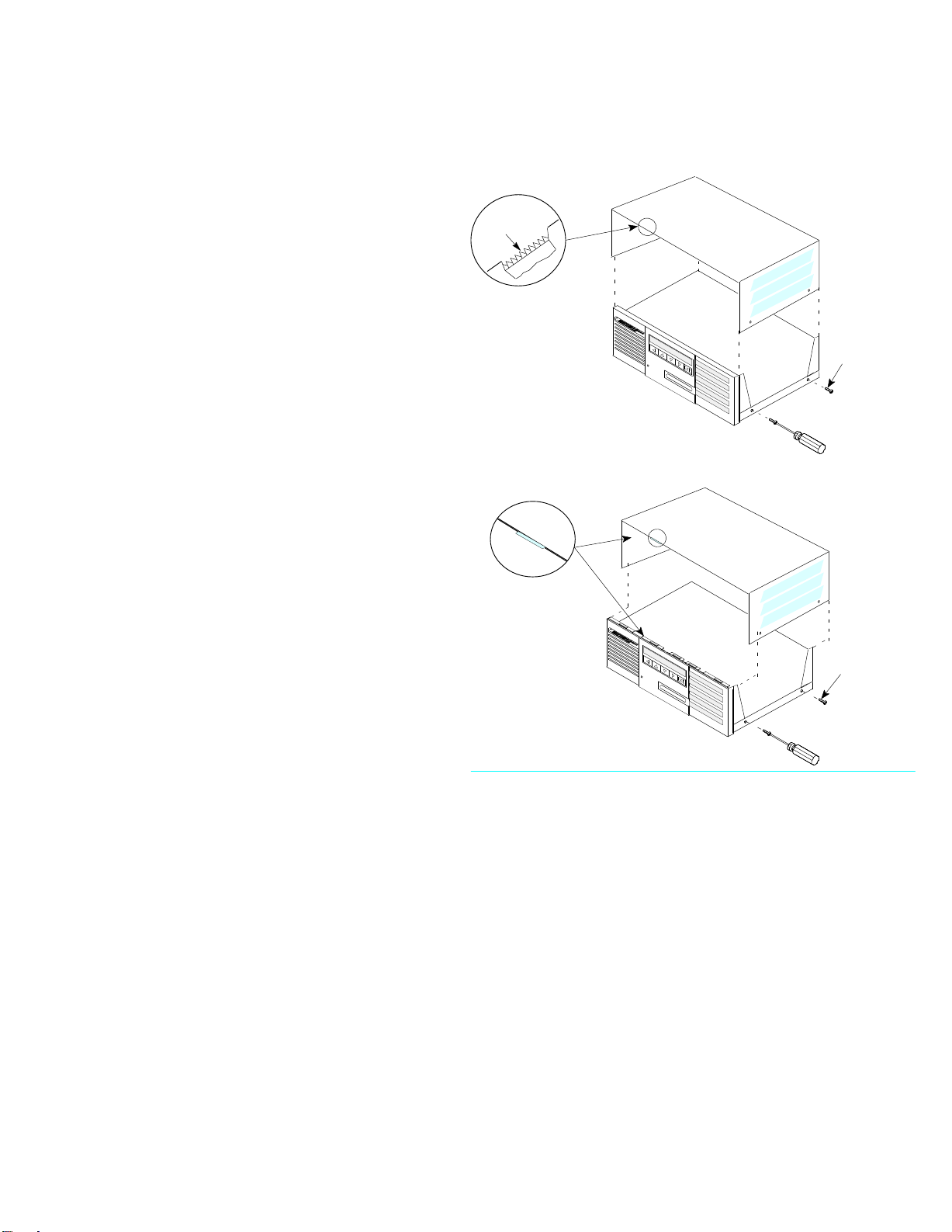
Task One:
Open the Unit
To open the unit proceed with the following:
1. Remove power from the unit.
Do not skip this step
WARNING:
!
2. Remove the cover from the unit.
Mounting
Screw
(
4)
Metallic
Fingers
Mounting
Screw (4)
Pull cove
r t
owards th
e b
ack o
f t
h
e u
nit
, u
nti
l t
he
fron
t f
langes ar
e u
ncoupled
; t
he
n l
if
t o
ff cover.
Fron
t F
langes
CE-Approved Unit
Installing
the Power Supply into an Integration Unit
3
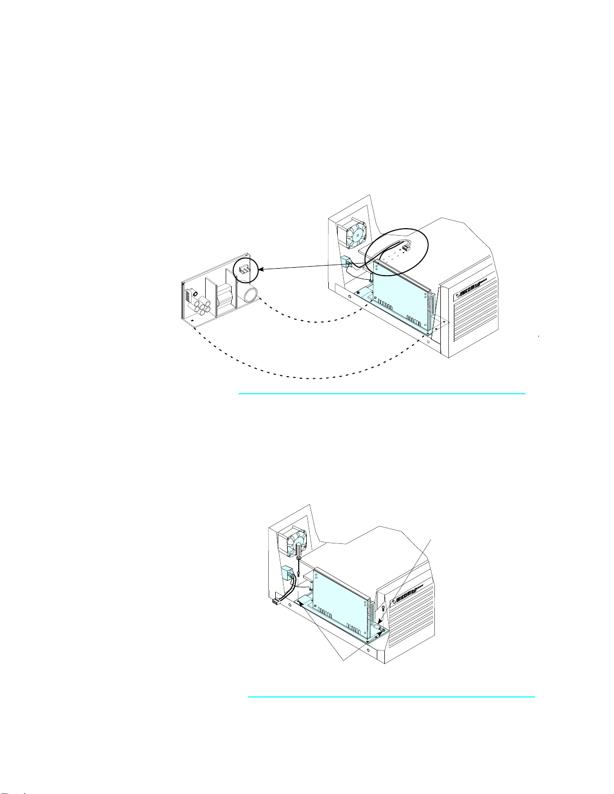
Task Two:
Disconnect and Remove the Power Supply
Note: The placement of the ac connector on the power supply may vary depending on the model
you are currently using.
To disconnect and remove the power supply, proceed as follows:
1. Disconnect the connector on the
power supply.
Inside
Front scre
w a
lso secures
a p
ower supply grounding
strap.
Unscrew the two screws
which hold the power
supply in the chassis.
Harness
2. Unscrew the two screws which
hold the power supply in the
chassis. Unscrew the screw at the
front of the unit and release the
power supply grounding strap.
Installing
the Power Supply into an Integration Unit
4
Task Two: (cont.)
Disconnect and Remove the Power Supply
3. Remove the power supply from the
unit. Gently move it around until it
clears the area.
4. Disconnect the power supply
connector from the Communication
Control Modules (CCM).
Note: The power supply cable
assembly and connector may
vary depending on model.
Pull up on cover to re-
lease the connector.
Connector
is
released.
CCM
This may or may not
have a connector.

Installing
the Power Supply into an Integration Unit
5
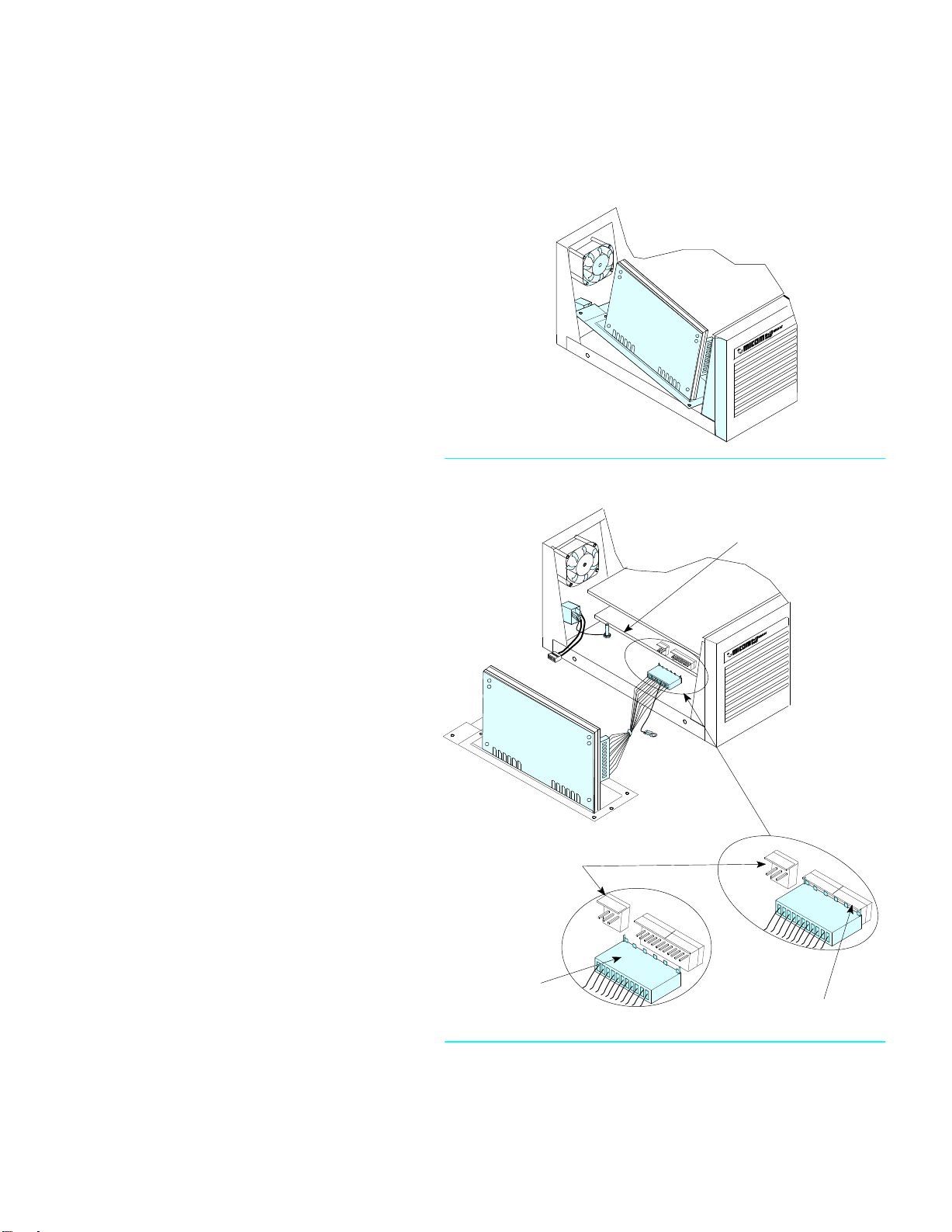
Task Three:
Install the New Power Supply
To install the new power supply, proceed as follows:
1. Connect the AC connector on the
new power supply.
3. Connect the power connector to the CCM
inside the unit as shown.
2. Reposition the power supply in the unit.
Ac Connector

Installing the Power Supply into an Integration Unit
6
4. Position the green grounding strap in
the screw, align the holes in the front
of the unit, and attach.
5. Screw in the back screw.
6. Reattach the power connectors to the
power supply.
Position the
grounding strap
Do not skip this step
WARNING:
!
Installing
the Power Supply into an Integration Unit
7
Task Four:
Install the Cover
Replace any additional spacers in the unit.
Position the cover over the unit and
reattach the screws
Mounting
Screw
(
4)
Metallic
Fingers
Mounting
Screw (4)
Place cove
r t
o t
h
e b
ack (abou
t 1 i
nch
) a
nd
slid
e i
t t
o m
at
e w
it
h t
h
e f
ront chassis flanges.
Fron
t F
langes
CE-Approved Unit
The installation of the new power supply is now complete.

PCR 1077D
Company Name
Address
How might we improve this manual?
Did you find any errors in the manual? (Please reference page, paragraph, table or figure
number)
How would you rate the manual overall? ----
Are the installation instructions effective? ----
Are the operating instructions clear and complete? ----
Is the manual properly organized?----
Is the artwork clear and easy to understand? ----
Is the index useful? ----
READER'S COMMENTS
MICOM welcomes your evaluation of this manual and any suggestions you may have.
These help us to improve the quality and usefulness of our publications.
Manual Name Part No.
Excellent Good Fair Poor
Name Title
Telephone ( )
Thank you for taking the time to fill out this form.
Installing the Power Supply 800-1868-43, Rev A

Fold Here
From: NO POSTAGE
NECESSARY
IF MAILED
IN THE
UNITED STATES
BUSINESS REPLY MAIL
FIRST
CLASS PERMIT
NO. 906 SIMI VALLEY
, CA
93062
POST
AGE WILL
BE P
AID BY
ADDRESSEE
MICOM Communications Corp.
4100 Los Angeles Avenue
Simi Valley, CA 93063–9949
FOLD AS MARKED AND T
APE CLOSED BEFORE MAILING.
PLEASE DO NOT ST
APLE.
ATTENTION: Manager, Technical Publications
Table of contents


