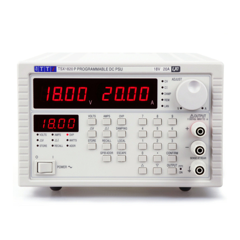
TTI TSX Series User manual

THURLBY THANDAR INSTRUMENTS
INSTRUCTION MANUAL
TSX Series
Programmable High Current DCPowerSupplies

Table of Contents
Specification 3
Safety 5
EMC 6
Installation 7
Manual Operation 8
Maintenance and Repair 11
Remote Operation 12
ARC Interface 13
Remote Commands 22
Instructions en Francais
Sécurité 34
Montage 35
Fonctionnement manuel 36
Entretien et Réparations 40
Fonctionnement à distance 41
Commandes à distance 52
Bedienungsanleitung auf Deutsch
Sicherheit 64
Installation 65
Handbedienung 66
Wartung und Instandsetzung 70
Fernbetrieb 71
Fernbefehle 82
1

EC Declaration of Conformity
We Thurlby Thandar Instruments Ltd
Glebe Road
Huntingdon
Cambridgeshire PE29 7DR
England
declare that the
TSX3510P & TSX1820P Programmable Power Supplies
meet the intent of the EMC Directive 2004/108/EC and the Low Voltage Directive 2006/95/EC.
Compliance was demonstrated by conformance to the following specifications which have been
listed in the Official Journal of the European Communities.
EMC
Emissions: a) EN61326-1 (2006) Radiated, Class B
b) EN61326-1 (2006) Conducted, Class B
c) EN61326-1 (2006) Harmonics, referring to EN61000-3-2 (2006)
Immunity: EN61326-1 (2006) Immunity Table 1, referring to:
a) EN61000-4-2 (1995) Electrostatic Discharge
b) EN61000-4-3 (2006) Electromagnetic Field
c) EN61000-4-11 (2004) Voltage Interrupt
d) EN61000-4-4 (2004) Fast Transient
e) EN61000-4-5 (2006) Surge
f) EN61000-4-6 (2007) Conducted RF
Performance levels achieved are detailed in the user manual.
Safety
EN61010-1 Installation Category II, Pollution Degree 2.
CHRIS WILDING
TECHNICAL DIRECTOR
2 May 2009
2

Specification
OUTPUT SPECIFICATIONS
Output Voltage Range: 0V to 35.3V (35V/10A); 0V to 18.15V (18V/20A).
Output Current Range: 0.01A to 10.2A (35V/10A); 0.01A to 20.2A (18V/20A).
Output Voltage Setting: Direct keyboard entry or quasi-analogue rotary control; setting
resolution 10mV.
Output Current Setting: Direct keyboard entry or quasi-analogue rotary control; setting
resolution 10mA.
Output Mode: Constant voltage or constant current with automatic crossover.
Output Switch: Electronic. Preset voltage and current displayed when off.
Output Terminals: 4mm terminals on front panel, screw terminals at rear.
Sensing: Remote via rear panel screw terminals or direct via shorting strip
(supplied).
Output Impedance: <1mΩ in constant voltage mode.
>5kΩin constant current mode (voltage limit at max.).
Output Protection: Forward protection by Over-Voltage-Protection (OVP) trip;
maximum voltage that should be applied to the terminals is 50V.
Reverse protection by diode clamp for reverse currents up to 3A.
OVP Setting: Direct keyboard entry.
OVP Range: 1V to 40V (35V/10A); 1V to 25V (18V/20A).
OVP Delay: <200µs
Load & Line Regulation: <0.01% of maximum output for 90% load change or 10% line
change.
Ripple & Noise: <1mV rms typical in constant voltage.
<3mA rms typical in constant current.
HF Common Mode Noise: Typically <3mV rms, <10mV peak.
Transient Response: 20µs to within 50mV of setting for 90% load change.
Temperature Coefficient: typically <100 ppm/°C.
Protection Functions: Overvoltage trip; regulator overtemperature; sense miswiring.
Status Indication: Output off lamp; constant voltage mode lamp;
constant current mode lamp; trip message on display.
METER SPECIFICATIONS
Meter Types: Dual 4 digit meters with 12·5mm (0.5") LEDs. Reading rate 4Hz.
Meter Resolution: 10mV, 10mA
Meter Accuracy: Voltage 0.2% of reading ± 1 digit, current 0.5% of reading ± 1 digit.
KEYBOARD FUNCTIONS
Delta Mode: Increase or decrease voltage or current in user-selectable steps.
Store/Recall: Store and recall voltage, current and OVP levels from non-volatile
memory (25 memories).
Interface Selection: Set digital interface type (RS232 or GPIB), baud rate and address.
3

Note: All voltage and current levels set via the keyboard are displayed on a separate 0·3” 4-digit
display. This entry preview system ensures that the user can observe the value entered before it
is effected thus avoiding possible error. The display is also used for setting additional functions.
When the output switch is on and no other function is selected, the display shows output power in
Watts.
DIGITAL INTERFACES
Operational Functions: Set voltage, set current, set OVP; set output on/off; read output
voltage; read output current; read output power.
RS232: Variable baud rate, 9600 baud maximum, 9 pin D-connector (female).
Fully compatible with ARC (Addressable RS232 Chain) system.
GPIB: Conforming with IEEE488.1 and IEEE488.2.
OUTPUT SPECIFICATIONS - REMOTE OPERATION
Output Voltage Setting: 12 bit resolution (10mV steps).
Output Current Setting: 12 bit resolution (10mA steps).
Setting Accuracy: Voltage: ±(0·1% + 10mV); Current: ± (0.2% + 20mA)
Output Switch: Electronic by interface command.
Readback Resolution: Voltage: 10mV over the entire range.
Current: 10mA over the entire range.
Readback Accuracy: Voltage: ± (0.2% of reading + 1 digit);
Current: ± (0.5% of reading + 1 digit).
RESPONSE TIME OVER RS232/GPIB:
Interface: <15ms (single command, buffer empty).
Power Supply: An internal time constant, T, (typically 22ms) governs the settling time
of a step voltage increase. Settling time to within 1% of the step
change = 4.6T, to 0.1% = 6.9T, to 0.01% = 9.2T; for example, after a
10V step the output will be within 1 digit (10mV = 0.1%) of its new
value in typically 150ms. For load current of 1 Amp or more, settling
times for downward steps will be very similar; however, response
times will be longer at low loads.
GENERAL
AC Input Voltage: 110V-120V AC or 220V-240V AC ±10%, 50/60Hz.
Installation Category II.
Power Consumption: 600VA max.
Operating Range: 5°C to +40°C, 20% to 80% RH.
Storage Range: –40°C to +70°C.
Environmental: Indoor use at altitudes up to 2000m, Pollution Degree 2.
Size: 200 x 140 x 385mm (WxHxD); half rack width x 3U height;
(optional rack mounting kit available)
Weight: 5.5kg.
Safety: Complies with EN61010-1
EMC: Complies with EN61326-1
4

Safety
This power supply is a Safety Class I instrument according to IEC classification and has been
designed to meet the requirements of EN61010-1 (Safety Requirements for Electrical Equipment
for Measurement, Control and Laboratory Use). It is an Installation Category II instrument
intended for operation from a normal single phase supply.
This instrument has been tested in accordance with EN61010-1 and has been supplied in a safe
condition. This instruction manual contains some information and warnings which have to be
followed by the user to ensure safe operation and to retain the instrument in a safe condition.
This instrument has been designed for indoor use in a Pollution Degree 2 environment in the
temperature range 5°C to 40°C, 20% - 80% RH (non-condensing). It may occasionally be
subjected to temperatures between +5°C and –10°C without degradation of its safety. Do not
operate while condensation is present.
Use of this instrument in a manner not specified by these instructions may impair the safety
protection provided. Do not operate the instrument outside its rated supply voltages or
environmental range.
WARNING! THIS INSTRUMENT MUST BE EARTHED
Any interruption of the mains earth conductor inside or outside the instrument will make the
instrument dangerous. Intentional interruption is prohibited. The protective action must not be
negated by the use of an extension cord without a protective conductor.
When the instrument is connected to its supply, terminals may be live and opening the covers or
removal of parts (except those to which access can be gained by hand) is likely to expose live
parts. The apparatus shall be disconnected from all voltage sources before it is opened for any
adjustment, replacement, maintenance or repair. Capacitors inside the power supply may still be
charged even if the power supply has been disconnected from all voltage sources but will be
safely discharged about 10 minutes after switching off power.
Any adjustment, maintenance and repair of the opened instrument under voltage shall be avoided
as far as possible and, if inevitable, shall be carried out only by a skilled person who is aware of
the hazard involved.
This instrument uses a Lithium button cell for non-volatile memory battery back-up; typical life is 5
years. In the event of replacement becoming necessary, replace only with a cell of the correct
type, i.e. 3V Li/Mn0220mm button cell type 2032. Exhausted cells must be disposed of carefully
in accordance with local regulations; do not cut open, incinerate, expose to temperatures above
60°C or attempt to recharge.
If the instrument is clearly defective, has been subject to mechanical damage, excessive moisture
or chemical corrosion the safety protection may be impaired and the apparatus should be
withdrawn from use and returned for checking and repair.
Make sure that only fuses with the required rated current and of the specified type are used for
replacement. The use of makeshift fuses and the short-circuiting of fuse holders is prohibited. Do
not wet the instrument when cleaning it.
The following symbols are used on the instrument and in this manual:-
Earth (ground) terminal.
mains supply OFF.
l mains supply ON.
alternating current (ac)
direct current (dc)
5

EMC
This instrument has been designed to meet the requirements of the EMC Directive 2004/108/EC.
Compliance was demonstrated by meeting the test limits of the following standards:
Emissions
EN61326-1 (2006) EMC product standard for Electrical Equipment for Measurement, Control and
Laboratory Use. Test limits used were:
a) Radiated: Class B
b) Conducted: Class B
c) Harmonics: EN61000-3-2 (2006) Class A; the instrument is Class A by product category.
Immunity
EN61326-1 (2006) EMC product standard for Electrical Equipment for Measurement, Control and
Laboratory Use.
Test methods, limits and performance achieved are shown below (requirement shown in
brackets):
a) EN61000-4-2 (1995) Electrostatic Discharge : 4kV air, 4kV contact, Performance A (B).
b) EN61000-4-3 (2006) Electromagnetic Field:
3V/m, 80% AM at 1kHz, 80MHz – 1GHz: Performance A (A) and 1.4GHz to 2GHz:
Performance A (A); 1V/m, 2.0GHz to 2.7GHz: Performance A (A).
c) EN61000-4-11 (2004) Voltage Interrupt: ½ cycle and 1 cycle, 0%: Performance A (B);
25 cycles, 70%: Performance A (C); 250 cycles, 0%: Performance C (C).
d) EN61000-4-4 (2004) Fast Transient, 1kV peak (AC line), 0·5kV peak (DC Outputs),
Performance A (B).
e) EN61000-4-5 (2006) Surge, 0·5kV (line to line), 1kV (line to ground), Performance A (B).
f) EN61000-4-6 (2007) Conducted RF, 3V, 80% AM at 1kHz (AC line only; DC Output
connections <3m, therefore not tested), Performance A (A).
According to EN61326-1 the definitions of performance criteria are:
Performance criterion A: ‘During test normal performance within the specification limits.’
Performance criterion B: ‘During test, temporary degradation, or loss of function or
performance which is self-recovering’.
Performance criterion C: ‘During test, temporary degradation, or loss of function or
performance which requires operator intervention or system reset occurs.’
Note that if operation in a high RF field is unavoidable it is good practice to connect the PSU to
the target system using screened leads which have been passed (together) through an absorbing
ferrite sleeve fitted close to the PSU terminals.
Cautions
To ensure continued compliance with the EMC directive observe the following precautions:
a) After opening the case for any reason ensure that all signal and ground connections are
remade correctly and that case screws are correctly refitted and tightened.
b) In the event of part replacement becoming necessary, only use components of an identical
type, see the Service Manual.
6

Installation
Mains Operating Voltage
Check that the instrument operating voltage marked on the rear panel is suitable for the local
supply. Should it be necessary to change the operating voltage, proceed as follows:
1. Ensure that the instrument is disconnected from the AC supply.
2. Remove the 6 screws holding the case upper and lift off the cover.
3. Change the appropriate zero-ohm links beside the transformer on the pcb:
Link LK5 only for 230V operation
Link LK1 and LK3 only for 115V operation
4. Re-assemble in the reverse order.
5. To comply with safety standard requirements the operating voltage on the rear panel must be
changed to clearly show the new voltage setting.
Mains Lead
When a three core mains lead with bare ends is provided this should be connected as follows:
BROWN - MAINS LIVE
BLUE - MAINS NEUTRAL
GREEN/YELLOW - EARTH
SafetyEarthSymbol
When fitting a fused plug a 5 amp fuse should be fitted inside the plug. As the colours of the
wires in the mains lead of this apparatus may not correspond with the coloured markings
identifying the terminals in your plug proceed as follows:
The wire which is coloured green-and-yellow must be connected to the terminal in the plug which
is marked by the letter E or by the safety earth symbol shown above or coloured green or green-
and-yellow.
The wire which is coloured blue must be connected to the terminal which is marked with the letter
N or coloured black.
The wire which is coloured brown must be connected to the terminal which is marked with the
letter L or coloured red.
WARNING! THIS APPARATUS MUST BE EARTHED.
Any interruption of the protective conductor inside or outside the apparatus or disconnection of
the protective earth terminal is likely to make the apparatus dangerous. Intentional interruption is
prohibited.
7

Manual Operation
Front Panel
The POWER switch is used to apply line voltage to the instrument. When switched to on (l) the
instrument will be powered and the start-up procedure will be executed; this will take
approximately 5 second to complete. If all is well the settings from the last power-down will be
installed and the instrument will be ready for use.
The output terminals are located on the right of the front panel. The red terminal is positive and
the black terminal is negative. Connection to the output terminals can be made with any of the
following: 4mm plugs, spade terminals or wire ends. To minimise voltage drop, the connecting
leads to the load should be of an adequate wire gauge and be kept short. The output terminals
are duplicated on the rear panel, together with the sense terminals.
The keyboard is located to the left of the output terminals. This consists of 27 keys and a LED
indicating the instrument output status. The use of the keyboard to control all instrument functions
is discussed in the following sections.
To the left of the keyboard is the status display which consists of a 4-digit, 7-segment display and
10 LEDs. Normally the status display will show the output power (in Watts) when the output is on
or will be blank when the output is off; however, other information will appear when selections are
made from the keyboard. The relevant annunciator LED will indicate what the contents of the
display represent at any time.
Above the keyboard are the main displays and LED indicators which show the conditions of the
output. The displays show the set voltage and set current when the output is off and the voltage
at the output terminals and output current when the output is on.
To the right of the LED indicators is a continuously rotating control which may be used to make
fine adjustments to voltage or current as described later.
General Principles of Manual Operation
The following sections explain in detail the use of the keyboard to control all instrument functions.
If an error is encountered during keyboard operation the status display will show Ennn where nnn
is a decimal number. A full list of possible errors is given in the STATUS REPORTING section.
Set Voltage
The set voltage is normally shown in the top left hand display marked V. The exception to this is
when the output is on and in constant current (CI) mode. In this case the actual output voltage will
be less than the set value and will be shown instead.
To set the voltage press the VOLTS key. The status display will show the set voltage value and
the VOLTS LED will light. A new value may now be entered from the numeric keypad. The value
will be in Volts and the POINT key may be used to enter decimal digits. Once the required value
is entered press the CONFIRM key and the set voltage will be updated immediately. To exit
without making any changes press the ESCAPE key. If a mistake is made during entry press the
VOLTS key and start again. The maximum and minimum values accepted will depend on the
particular model, see the specification section for details.
Set Current
When the output is off the set current is shown in the top right hand display marked A. When the
output is on and in constant voltage (CV) mode the output current is shown. When in constant
current (CI) mode the output current is equal to the set current and this is shown.
To set the current press the AMPS key. The status display will show the set current value and the
AMPS LED will light. A new value may now be entered from the numeric keypad. The value will
be in Amps and the POINT key may be used to enter decimal digits.
8

Once the required value is entered press the CONFIRM key and the set current will be updated
immediately. To exit without making any changes press the ESCAPE key. If a mistake is made
during entry press the AMPS key and start again.
The maximum and minimum values accepted will depend on the particular model, see the
specification section for details.
Set OVP
The Over-Voltage Protection (OVP) value is not shown in the main display; however, it is active
and if at any time the actual value of the output voltage exceeds the set value the OVP circuit will
immediately shut down the output, thus avoiding any damage to the circuit under test. The OVP
circuit will protect against adjustments by the user or the GPIB or RS232, external voltages
impressed across the output terminals, or a failure in the circuitry of the instrument itself. If the
OVP circuit trips for any reason the main displays will both show triP and the output will be
shut down, i.e. switched off. The system will then attempt to recover from the trip and if
successful the triP message will be removed and normal operation will resume.
To set the OVP press the OVP key. The status display will show the set OVP value and the OVP
LED will light. A new value may now be entered from the numeric keypad. The value will be in
VOLTS and the POINT key may be used to enter decimal digits. Once the required value is
entered press the CONFIRM key and the set OVP will be updated immediately. To exit without
making any changes press the ESCAPE key. If a mistake is made during entry press the OVP
key and start again.
The maximum and minimum values accepted will depend on the particular model, see the
specification section for details.
Delta Volts
Delta Volts mode is entered by pressing the DeltaV key. The status display will show the set Delta
Volts value and the DeltaV LED will light. A new value may now be entered from the numeric
keypad. The value will be in Volts and the POINT key may be used to enter decimal digits. Once
the required value is entered press the CONFIRM key and the set Delta Volts value will be
updated immediately. To exit without making any changes press the ESCAPE key. If a mistake is
made during entry press the DeltaV key and start again.
While in DeltaV mode, i.e. while the DeltaV LED is on, the UP and DOWN keys are active and will
increment or decrement the set volts value by the set DeltaV value shown in the status display.
The VOLTS LED next to the knob will also be on indicating that the knob is active for adjusting
volts. Turning the knob will increment or decrement the set volts value in 10mV steps irrespective
of the set DeltaV value.
The maximum value for DeltaV is 1·00V. The minimum value is 0·00V.
Delta Amps
Delta Amps mode is entered by pressing the Deltal key. The status display will show the set Delta
Amps value and the Deltal LED will light. A new value may now be entered from the numeric
keypad. The value will be in Amps and the POINT key may be used to enter decimal digits. Once
the required value is entered press the CONFIRM key and the set Delta Amps value will be
updated immediately. To exit without making any changes press the ESCAPE key. If a mistake is
made during entry press the Deltal key and start again.
Whilst in Delta Amps mode, i.e. while the Deltal LED is on, the UP and DOWN keys are active
and will increment or decrement the set current value by the set Delta Amps value shown in the
status display. The AMPS LED next to the knob will also be on indicating that the knob is active
for adjusting current. Turning the knob will increment or decrement the set current value in 10mA
steps irrespective of the set Delta Amps value.
The maximum value for Delta Amps is 1·00A. The minimum value is 0·00A.
9

Current Meter Damping
The output current meter damping is toggled on and off by pressing the DAMPING key. When
damping is on the DAMP LED will also be on.
Output On/Off
The output is alternatively turned on and off by pressing the OUTPUT key. The status is shown by
the ON LED next to the key.
Store Settings
The instrument contains 25 stores each capable of holding the entire set-up. The stored data is
non-volatile and is retained while power is off.
To save the instrument set-up to a store press the STORE key. The status display will show the
number of the last store which was accessed. This store may be used or a new store number
may be entered from the numeric key pad. When the required value is displayed press the
CONFIRM key to store the data in that store. Pressing the ESCAPE key will exit without making
any changes.
Recall Settings
The instrument contains 25 stores each capable of holding the entire set-up. The stored data is
non-volatile and is retained while power is off.
To recall the instrument set up from a store press the RECALL key. The status display will show
the number of the last store which was accessed. This store may be used or a new store number
may be entered from the numeric key pad. When the required value is displayed press the
CONFIRM key to recall the data from that store. Pressing the ESCAPE key will exit without
making any changes.
Thermal Trip
If the instrument overheads a thermal trip will occur and the main displays will show the triP
message. The output will then be shut down, i.e. the output will be switched off. This condition will
persist until the instrument cools to below the trip temperature value, when the output will be
usable again.
Connection to the Load
Output Terminals
Connection to the front panel output terminals can be made with 4mm plugs, spade terminals or
wire ends. To minimise voltage drop, the connecting leads to the load should be of an adequate
wire gauge and be kept short. Load wires should also be twisted together to reduce inductance.
The output is fully floating and either terminal can be connected to ground or raised by up to
300V peak above true ground; however, such voltages are hazardous and great care should be
taken.
The current limit can be set to limit the continuous output current to levels down to 10mA.
However, in common with all precision bench power supplies, a capacitor is connected across the
output to maintain stability and good transient response. This capacitor charges to the output
voltage, and short circuiting of the output will produce a short current pulse as the capacitor
discharges which is independent of the current limit setting.
Sense Terminals
To overcome errors introduced by connecting lead resistance at higher currents (10millOhm of
lead resistance will drop 0·2V at 20Amps) the remote sending facility should be used. Remove
the two shorting links made between the rear output and sense terminals and connect the sense
terminals directly to the load; the power connections may be made from either the front or rear
terminals. To ensure good coupling between the output and sense, the sense wires should be
twisted with their corresponding output leads before the output leads are twisted together.
10

The voltage drop in each output lead must not exceed 1V.
The shorting links should be re-made between the rear sense and output terminals when remote
sensing is not being used. However, the sense connection is also made internally through a low
value resistor and only a small error between the set and actual voltage will result if the links are
left disconnected.
Sense Miswiring Trip
The output will be tripped off if the sense wires are wired to the wrong output or if an attempt is
made to draw power from the sense wires; the triP message will be shown in both displays.
The system will then attempt to recover from the trip and, if successful (because the wiring has
been corrected), the triP message will be removed and normal operation will resume.
Output Protection
In addition to OVP for forward overvoltage protection, the output is protected from reverse
voltages by a diode; the continuous reverse current must not exceed 3 Amps, although transients
can be much higher.
Ventilation
These instruments are very efficient but nevertheless can generate significant heat at full power.
The supplies rely on convection cooling only and it is therefore important that ventilation is never
restricted if performance and safety are to be maintained. If the supplies are mounted in a
restricted space, eg. a 19 inch rack, then adequate ventilation must be ensured by using, for
example, a fan tray.
Maintenance and Repair
The Manufacturers or their agents overseas will provide repair for any unit developing a fault.
Where owners wish to undertake their own maintenance work, this should only be done by skilled
personnel in conjunction with the service manual which may be purchased directly from the
Manufacturers or their agents overseas.
Fuse
The correct fuse type for all models and AC supply ranges is:
10 Amp 250V HBC time-lag, 5 x 20 mm
Make sure that only fuses with the required rated current and of the specified type are used for
replacement. The use of makeshift fuses and the short-circuiting of fuse-holders is prohibited.
To replace the fuse, first disconnect the instrument from the AC supply. Remove the 6 cover
securing screws and lift off the cover. Replace the fuse with one of the correct type and refit the
cover.
Note that the main function of the fuse is to make the instrument safe and limit damage in the
event of failure of one of the switching devices. If a fuse fails it is therefore very likely that the
replacement will also blow, because the supply has developed a fault; in such circumstances the
instrument will need to be returned to the manufacturer for service.
Cleaning
If the PSU requires cleaning use a cloth that is only lightly dampened with water or a mild
detergent. Polish the display window with a soft dry cloth.
WARNING! TO AVOID ELECTRIC SHOCK, OR DAMAGE TO THE PSU, NEVER ALLOW
WATER TO GET INSIDE THE CASE. TO AVOID DAMAGE TO THE CASE OR DISPLAY
WINDOW NEVER CLEAN WITH SOLVENTS.
11

Remote Operation
The following sections detail the operation of the instrument via both GPIB and ARC. Where
operation is identical no distinction is made between the two. Where difference occur these are
detailed in the appropriate sections or in some cases separate sections for GPIB and ARC. It is
therefore only necessary to read the general sections and those sections specific to the interface
of interest.
Interface Selection
All power supplies in the range are fitted with both an ARC (Addressable RS232 Chain) interface
and a GPIB interface. Before an interface can be used it must be selected and assigned an
address and/or baud rate. To select an interface press the I/F key. The status display will show
either “232” if RS232 is currently selected or “488” if GPIB is selected. The selected interface
may be changed by pressing the UP or DOWN keys. Once the required interface is in the display
press the CONFIRM key to make it active. Pressing the ESCAPE key will exit without making any
changes.
Address and Baud Rate Selection
For successful operation each instrument connected to the ARC or GPIB must be assigned a
unique address and, in the case of ARC, all must be set to the same baud rate.
Pressing the BAUD/ADDR key will alternately show baud rate or address if RS232 is selected or
address only if GPIB is selected;the BAUD/ADDR LED will also be on.
To select an alternative baud rate the UP and DOWN keys are used to cycle through all available
values. When the required value is displayed press the CONFIRM key to make it active. Pressing
the ESCAPE key will exit without making any changes. Selectable baud rates are 300, 600, 1200,
2400, 4800 and 9600.
To select an alternative address enter the required number from the numeric key pad. When the
required value is displayed press the CONFIRM key to make it active. Pressing the ESCAPE key
will exit without making any changes. The range of addresses accepted is 0 to 30.
A change of address will become active immediately it is entered from the keyboard and the
device will no longer respond to the previous address.
All device operations are performed through a single primary address, no secondary addressing
is used. The default address, i.e. after a non-volatile ram failure, is 11. When the address is
changed the new setting is stored in non-volatile ram, and will remain unchanged even while
power is off.
The RS232 interface may also be used in a simple non-addressable mode without modification.
Remote/Local Operation
At power-on the instrument will be in the local state with the REMOTE LED off. In this state all
keyboard operations are possible. When the instrument is addressed (to talk or listen) the remote
state will be entered and the REMOTE LED will be turned on. In this state the keyboard is locked
out and remote commands only will be processed. The instrument may be returned to the local
state by pressing the LOCAL key; however, the effect of this action will remain only until the
instrument is addressed again or receives another character from the interface, when the remote
state will once again be entered. The Controller may disable the LOCAL key under GPIB control
by sending a Local Lock Out command (LLO); the instrument keyboard will then remain
inoperative until the Controller sends a Go To Local command (GTL) or sets the REN interface
line false.
12

ARC Interface
ARC Interface Connections
The 9-way D-type serial interface connector is located on the instrument rear panel. The pin
connections are as shown below:
Pin Name Description
1 - No internal Connection
2 TXD Transmitted data from instrument
3 RXD Received data to instrument
4 - No internal connection
5 GND Signal ground
6 - No internal connection
7 RXD2 Secondary received data (see diagram)
8 TXD2 Secondary transmitted data (see diagram)
9 GND Signal ground
Pins 2, 3 and 5 may be used as a conventional RS232 interface with XON/XOFF handshaking.
Pins 7, 8 and 9 are additionally used when the instrument is connected to the ARC interface.
Using a simple cable assembly, a `daisy chain' connection system between any number of
instruments, up to the maximum of 32 can be made, as shown below:
The daisy chain consists of the transmit data (TXD), receive date (RXD) and signal ground lines
only. There are no control/handshake lines. This makes XON/XOFF protocol essential and allows
the inter-connection between instruments to contain just 3 wires. The wiring of the adaptor cable
is shown below:
All instruments on the interface must be set to the same baud rate and all must be powered on,
otherwise instruments further down the daisy chain will not receive any data or commands.
13

The ARC standard for the other interface parameters is as follows; in these power supplies (and
most other ARC instruments) they are fixed.
Start bits 1
Data bits 8
Parity None
Stop bits 1
ARC Character Set
Because of the need for XON/XOFF handshake it is possible to send ASCII coded data only;
binary blocks are not allowed. Bit 7 of ASCII codes is ignored, i.e. assumed to be low. No
distinction is made between upper and lower case characters in command mnemonics and they
may be freely mixed. The ASCII codes below 20H (space) are reserved for interface control.
ARC Interface Control Codes
All instruments intended for use on the ARC bus use the following set of interface control codes.
Codes between 00H and 1FH which are not listed here as having a particular meaning are
reserved for future use and will be ignored. Mixing interface control codes inside instrument
commands is not allowed except as stated below for CR and LF codes and XON and XOFF
codes.
When an instrument is first powered on it will automatically enter the Non- Addressable mode. In
this mode the instrument is not addressable and will not respond to any address commands. This
allows the instrument to function as a normal RS232 controllable device. This mode may be
locked by sending the Lock Non-Addressable mode control code 04H (LNA). The controller and
instrument can now freely use all 8 bit codes and binary blocks but all interface control codes are
ignored. To return to addressable mode the instrument must be powered off.
To enable addressable mode after a instrument has been powered on the Set Addressable Mode
control code, 02H (SAM), must be sent. This will then enable all instruments connected to the
ARC bus to respond to all interface control codes. To return to Non-Addressable mode the Lock
Non-Addressable mode control code must be sent which will disable addressable mode until the
instruments are powered off.
Before an instrument is sent a command it must be addressed to listen by sending the Listen
Address control code, 12H (LAD), followed by a single character which has the lower 5 bits
corresponding to the unique address of the required instrument, e.g. the codes A-Z or a-z give
the addresses 1-26 inclusive while @ is address 0 and so on. Once addressed to listen the
instrument will read and act upon any commands sent until the listen mode is cancelled.
Because of the asynchronous nature of the interface it is necessary for the controller to be
informed that an instrument has accepted the listen address sequence and is ready to receive
commands. The controller will therefore wait for code 06H (ACK) before sending any commands,
The addressed instrument will provide this ACK. The controller should time-out and try again if no
ACK is received within 5 seconds.
Listen mode will be cancelled by any of the following interface control codes being received:
12H LAD Listen Address followed by an address not
belonging to this instrument.
14H TAD Talk Address for any instrument.
03H UNA Universal Unaddress control code.
04H LNA Lock Non-Addressable mode control code.
18H UDC Universal Device Clear.
14

Before a response can be read from an instrument it must be addressed to talk by sending the
Talk Address control code, 14H (TAD) followed by a single character which has the lower 5 bits
corresponding to the unique address of the required instrument, as for the listen address control
code above. Once addressed to talk the instrument will send the response message it has
available, if any, and then exit the talk addressed state. Only one response message will be sent
each time the instrument is addressed to talk.
Talk mode will be cancelled by any of the following interface control codes being received:
12H LAD Listen Address for any instrument.
14H TAD Talk Address followed by an address not
belonging to this instrument.
03H UNA Universal Unaddress control code.
04H LNA Lock Non-Addressable mode control code.
18H UDC Universal Device Clear.
Talk mode will also be cancelled when the instrument has completed sending a response
message or has nothing to say.
The interface code 0AH (LF) is the Universal Command and response Terminator (UCT); it must
be the last code sent in all commands and will be the last code sent in all responses.
The interface code 0DH (CR) may be used as required to aid the formatting of commands; it will
be ignored by all instruments. Most instruments will terminate responses with CR followed by LF.
The interface code 13H (XOFF) may be sent at any time by a listener (instrument or controller) to
suspend the output of a talker. The listener must send 11H (XON) before the talker will resume
sending. This is the only form of handshake control supported by ARC.
ARC Interface Control Code List
02H SAM Set Addressable mode.
03H UNA Universal Unaddress control code.
04H LNA Lock Non-Addressable mode control code.
06H ACK Acknowledge that listen address received.
0AH UCT Universal Command and response Terminator.
0DH CR Formatting code, otherwise ignored.
11H XON Restart transmission.
12H LAD Listen Address - must be followed by an address belonging to
the required instrument.
13H XOFF Stop transmission.
14H TAD Talk Address - must be followed by an address belonging to the
required instrument.
18H UDC Universal Device Clear.
GPIB Interface
The 24-way GPIB connector is located on the instrument rear panel.
The pin connections are as specified in IEEE Std. 488.1-1987 and the instruments in the range
comply with IEEE Std. 488.1-1987 and IEEE Std. 488.2-1987 and contain the following IEEE
488.1 subsets.
15

GPIB Subsets
This instrument contains the following IEEE 488.1 subsets:
Source Handshake SH1
Acceptor Handshake AH1
Talker T6
Listener L4
Service Request SR1
Remote Local RL1
Parallel Poll PP1
Device Clear DC1
Device Trigger DT0*
Controller C0
Electrical Interface E2
* Although no Device Trigger capability is included, the GET message will not cause a
command error unless its position in the input stream dictates that it should; e.g. buried
inside a <PROGRAM MESSAGE UNIT>.
GPIB IEEE Std. 488.2 Error Handling
The IEEE 488.2 UNTERMINATED error (addressed to talk with nothing to say) is handled as follows.
If the instrument is addressed to talk and the response formatter is inactive and the input queue
is empty then the UNTERMINATED error is generated. This will cause the Query Error bit to be set
in the Standard Event Status Register, a value of 3 to be placed in the Query Error Register and
the parser to be reset. See the STATUS REPORTING CAPABILITIES section for further
information.
The IEEE 488.2 INTERRUPTED error is handled as follows. If the response formatter is waiting to
send a response message and a <PROGRAM MESSAGE TERMINATOR> has been read by the parser
or the input queue contains more than one END message then the instrument has been
INTERRUPTED and an error is generated. This will cause the Query Error bit to be set in the
Standard Event Status Register, a value of 1 to be placed in the Query Error Register and the
response formatter to be reset thus clearing the output queue. The parser will then start parsing
the next <PROGRAM MESSAGE UNIT> from the input queue. See the STATUS REPORTING
CAPABILITIES section for further information.
The IEEE 488.2 DEADLOCK error is handled as follows. If the response formatter is waiting to send
a response message and the input queue becomes full then the instrument enters the DEADLOCK
state and an error is generated. This will cause the Query Error bit to be set in the Standard Event
Status Register, a value of 2 to be placed in the Query Error Register and the response formatter
to be reset thus clearing the output queue. The parser will then start parsing the next <PROGRAM
MESSAGE UNIT> from the input queue. See the STATUS REPORTING CAPABILITIES section for
further information.
GPIB Parallel Poll
The power supplies offer complete parallel poll capabilities. The Parallel Poll Enable Register is
set to specify which bits in the Status Byte Register are to be used to form the ist local message
The Parallel Poll Enable Register is set by the ∗PRE <nrf> command and read by the ∗PRE?
command. The value in the Parallel Poll Enable Register is ANDed with the Status Byte Register;
if the result is zero then the value of ist is 0 otherwise the value of ist is 1.
The instrument must also be configured so that the value of ist can be returned to the controller
during a parallel poll operation. The instrument is configured by the controller sending a Parallel
Poll Configure command (PPC) followed by a Parallel Poll Enable command (PPE). The bits in
the PPE command are shown below:
16

bit 7 = X don't care
bit 6 = 1
bit 5 = 1 Parallel poll enable
bit 4 = 0
bit 3 = Sense - sense of the response bit; 0 = low, 1 = high
bit 2 = ?
bit 1 = ? bit position of the response
bit 0 = ?
Example. To return the RQS bit (bit 6 of the Status Byte Register) as a 1 when true and a 0 when
false in bit position 1 in response to a parallel poll operation send the following commands
∗PRE 64<pmt>, then PPC followed by 69H (PPE)
The parallel poll response from the generator will then be 00H if RQS is 0 and 01H if RQS is 1.
During parallel poll response the DIO interface lines are resistively terminated (passive
termination). This allows multiple devices to share the same response bit position in either wired-
AND or wired-OR configuration, see IEEE 488.1 for more information.
Power on Settings
Most instrument settings are stored in non-volatile ram and will remain unchanged while power is
off. The following instrument status values are set at power on:
Status Byte Register = 0
* Service Request Enable Register = 0
Standard Event Status Register = 128 (pon bit set)
* Standard Event Status Enable Register = 0
Limit Event Status Register = 0 (Then set to show new limit status)
* Limit Event Status Enable Register = 0
Execution Error Register = 0
Query Error Register = 0
* Parallel Poll Enable Register = 0
* Registers marked thus are specific to the GPIB section of the instrument and are of limited
use in an ARC environment.
The standby state will be set and the instrument will be in local with the keyboard active. A
complete self-test will be performed just after power up and this will determine the values in the
Failed Output Register and the state of the FLT bit in the Status Byte Register.
Due to the non-volatile storage the power on settings are essentially modified by any command,
local or remote, which changes any value not listed above. If a defined state is require at start up
by the controller the *RST command should be issued which will load the settings as listed in the
description of that command.
If for any reason an error is detected at power up in the non-volatile ram a warning will be issued
and all settings will be returned to their default states as for a *RST command.
Status Reporting
This section describes the complete status model of the instrument. Note that some registers are
specific to the GPIB section of the instrument and are of limited use in an ARC environment.
17

Standard Event Status and Standard Event Status Enable Registers
These two registers are implemented as required by the IEEE std. 488.2.
Any bits set in the Standard Event Status Register which correspond to bits set in the Standard
Event Status Enable Register will cause the ESB bit to be set in the Status Byte Register.
The Standard Event Status Register is read and cleared by the ∗ESR? command. The Standard
Event Status Enable register is set by the ∗ESE <nrf> command and read by the ∗ESE?
command.
Bit 7 - Power On. Set when power is first applied to the instrument.
Bit 6 - Not used.
Bit 5 - Command Error. Set when a syntax type error is detected in a command from the
bus. The parser is reset and parsing continues at the next byte in the input stream.
Bit 4 - Execution Error. Set when an error is encountered while attempting to execute a
completely parsed command. The appropriate error number will be reported in the
Execution Error Register, as listed below:
001 Checksum error in non-volatile ram at power on.
002 Output stage failed to respond - possibly a system fault.
003 Output stage trip has occurred - attempting to recover.
100 Maximum set voltage value exceeded.
101 Maximum set amps value exceeded.
102 Minimum set voltage exceeded.
103 Minimum set amps value exceeded.
104 Maximum delta voltage value exceeded.
105 Maximum delta amps value exceeded.
107 Minimum set OVP value exceeded.
108 Maximum set OVP value exceeded.
109 Minimum delta amps value exceeded.
110 Minimum delta voltage value exceeded.
114 Illegal bus address requested.
115 Illegal store number.
116 Recall empty store requested.
117 Stored data is corrupt.
118 Output stage has tripped (OVP or Temperature).
119 Value out of range.
Bit 3 - Operation Time-out Error. Set when an attempt is made to set an output to a specific
voltage value, with verify specified, and the output Volts do not settle within 5
seconds. this can happen if, for example, a large value of capacitance exists across
the output and the current limit is set to a very low value.
Bit 2 - Query Error. Set when a query error occurs. The appropriate error number will be
reported in the Query Error Register as listed below.
1 Interrupted error
2 Deadlock error
3 Unterminated error
Bit 1 - Not used.
Bit 0 - Operation Complete. Set in response to the ∗OPC command.
18

Limit Event Status Register and Limit Event Status Enable Register
These two registers are implemented as an addition to the IEEE std.488.2. Their purpose is to
allow the controller to be informed of entry to and/or exist from current limit by any output.
Any bits set in the Limit Event Status Register which correspond to bits set in the Limit Event
Status Enable Register will cause the LIM bit to be set in the Status Byte Register.
The Limit Event Status Register is read and cleared by the LSR? command. The Limit Event
Status Enable register is set by the LSE<nrf> command and read by the LSE? command.
Bit 7 ... Bit 3 are not used.
Bit 2 - Set when an output trip has occurred.
Bit 1 - Set when output enters voltage limit.
Bit 0 - Set when output enters current limit.
Status Byte Register and Service Request Enable Register
These two registers are implemented as required by the IEEE std. 488.2.
Any bits set in the Status Byte Register which correspond to bits set in the Service Request
Enable Register will cause the RQS/MSS bit to be set in the Status Byte Register, thus generating
a Service Request on the bus.
The Status Byte Register is read either by the ∗STB? command, which will return MSS in bit 6, or
by a Serial Poll which will return RQS in bit 6. The Service Request Enable register is set by the
∗SRE <nrf> command and read by the ∗SRE? command.
Bit 7 - FLT. This is the fault bit which will be set when an output fault is detected,
i.e. an execution error 002 has occurred.
Bit 6 - RQS/MSS. This bit, as defined by IEEE Std. 488.2, contains both the Requesting
Service message and the Master Status Summary message. RQS is returned in
response to a Serial Poll and MSS is returned in response to the ∗STB? command.
Bit 5 - ESB. The Event Status Bit. This bit is set if any bits set in the Standard Event Status
Register correspond to bits set in the Standard Event Status Enable Register.
Bit 4 - MAV. The Message Available Bit. This will be set when the instrument has a
response message formatted and ready to send to the controller. The bit will be
cleared after the Response Message Terminator has been sent.
Bit 3 - Not used.
Bit 2 - Not used.
Bit 1 - Not used.
Bit 0 - LIM. The Limit status bit. This bit is set if any bits set in the Limit Event Status
Register correspond to bits set in the Limit Event Status Enable Register.
19
Other manuals for TSX Series
2
This manual suits for next models
2
Table of contents
Languages:
Other TTI Power Supply manuals
