Marco FRIIA HCS User manual

For more information visit www.marcobeveragesystems.com
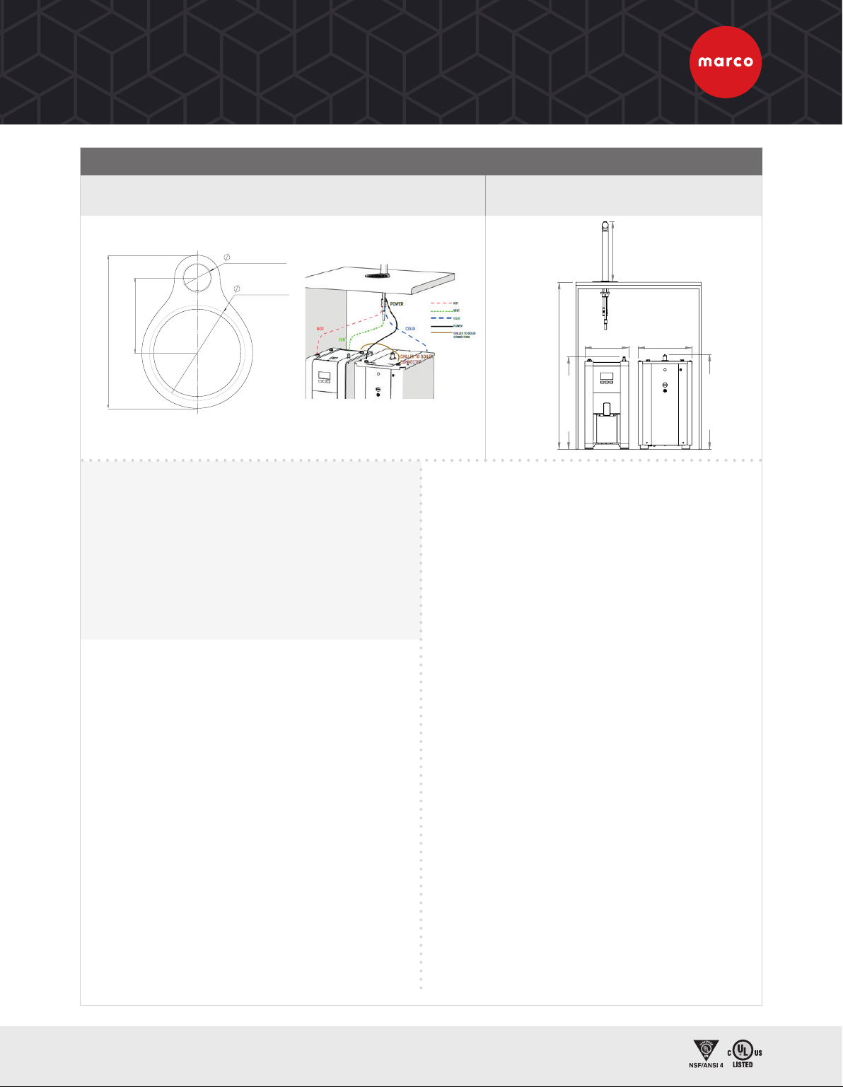
FRIIA HOT/COLD/SPARKLING
FRIIA HCS FRIIA HCS PLUS FONT DIMS
CHILLER/
CARBONATOR
BOILERS
FRIIA components (font, boiler and
chiller) are packed and shipped in
individual boxes. FRIIA Sparkling
variants require food-grade CO2
(not supplied by Marco).
PLEASE
NOTE
ORDER CODES (Complete bundle)
> FRIIA HCS (220/110v) 1000865US/1001865US
> FRIIA HCS Plus 1000867US
> Sleek, stylish font
combining hot/cold/
sparkling water
> 0.8 or 2.1 GAL boiler
option
CHILLER/CARBONATOR BOILER SYSTEM SET-UP
PRODUCT INFO SIZE PERFORMANCE SPECS PLUMBING, ELECTRICAL AND TECHNICAL SPECS
NAME
ORDER CODE
DIMENSIONS
(D X W X H inches)GAL/HR CUPS
/HR
POWER
@110V
PLUMBING
REQS
COMPRESSOR
POWER CHARGE REFRIGERANT
Chiller/
Carbonator
1000861US
17.1 x 10.2 x 17.9
7.9-11.8 GALS/hr based
on incoming water temp
of 59°F and output
water temp of 41-44°F
175-235
(ΔT =
18 °F)
180W
3/8”
Compression
or 3/8” John
Guest
1/8hp 45g R290
FONTS
NAME
ORDER CODE
DIMENSIONS
INC. DRIP TRAY
(D X W X H inches)
DIMENSIONS
EXCL. DRIP TRAY
(D X W X H inches)
TAP TO
COUNTER
(inches)
3b Font
1000862 6.6 x 4.7 x 11.2 5.4 x 1.1 x 11.2 9.7
NAME
PACKAGING
DIMENSIONS
(L x W x H inches)
WEIGHT
Fonts (all) 11.4 x 22.4 x 8.4 4.4lbs
Chiller 19.2 x 11.8 x 20.2 69.4lbs
MIX UC3 -
220v/110v 17.7 x 11.4 x 21.2 25lbs
MIX UC8 -
220v 17.7 x 11.4 x 27.5 30.8lbs
PACKAGING
9.7
11.2
5.4
PRODUCT INFO SIZE PERFORMANCE SPECS PLUMBING & ELECTRICAL REQS
NAME
ORDER CODE
DIMENSIONS
(D X W X H inches)
IMMEDIATE
DRAW OFF GAL/HR CUPS/HR POWER NEMA PLUMBING
REQS
MIX UC3 - 220v
1000880US 15.1 x 8.2 x 17.4 0.8 GAL
7.3 GAL
75
2.8kW
@ 220v L6-20P
3/8”
Compression
or 3/8” John
Guest
MIX UC3 - 110v
1001880US 3.6 GAL
1.4kW
@ 110v 5-15p
MIX UC8 - 220v
1000887US 15.1 x 8.2 x 24.2 2.1 GAL 2.8kW
@ 220v L6-20P
For more information visit www.marcobeveragesystems.com
FRIIA HC & FRIIA HCS
FRIIA HOT/COLD & FRIIA HOT/COLD/SPARKLING
COUNTER CUT-OUT WITH DRIP TRAY FRIIA HC (220/110V) 1000864US/1001864US
FRIIA HCS (220/110V) 1000865US/1001865US
VENTILATION REQUIREMENTS
FRONT VENTILATION: Ventilation grilles cut out of standard cabinet door.
SIDE VENTILATION: Ventilation grilles cut out of standard 600mm
cabinet. Grilles may be fitted on either side as long as they ventilate
into an open unobstructed area.
BASE VENTILATION: Ventilation grilles cut in base panel and base
plinth, a grille must also be cut out at the top of the cabinet.
• At least 2 x vents 260mm/10.2” w x 65mm/2.5 h
• The cabinet may be ventilated in many ways provided there are cut
outs placed near the base and another near the top of the cabinet
to take advantage of natural circulation.
UNPACKING INSTRUCTIONS
• The chiller must be handled only in a vertical position. Transporting
the appliance in a horizontal position can cause severe damage to
the refrigerator.
• Remove the exterior and interior packing. Packing materials
(especially any plastic bags) should be stored out of the reach
of children, as a potential source of danger. When disposing
packaging parts, please follow current regulations on the matter,
separating carton from plastic parts.
• Always check that the equipment that is delivered corresponds to
the model indicated in the accompanying document.
• The equipment is shipped in a cardboard box. Once the packaging
has been removed, check the equipment has not been damaged in
transit; if damage is found, notify the carrier.
ELECTRICAL INSTALLATION PROCEDURE
When installing the machine, always observe the local regulations and
standards. The appliance is supplied with a moulded power cord. A
suitable mains power supply socket should be available within easy
access of the appliance so that it can be disconnected easily after install.
The standard machines are supplied with a UK 3-pin plug. For
EU models a 2-pin CEE-7 plug will be supplied. US models will be
supplied with the suitable plug. A suitable mains power supply socket
should be available within easy access of the appliance so that it
can be disconnected easily after install. The wires from the font are
terminated in a Mini Fit connector which will plug into a similar Mini Fit
connector mounted on the top lid of the undercounter boiler.
PLUMBING INSTALLATION PROCEDURE
• Ensure that the equipment is installed according to local plumbing
& water regulations.
• Fit a stop valve on a cold water line and attach a 3/4” BSP male
fitting, (eg. 3/4” x 1/2” 311 or washing machine type stop valve).
Suitable fittings are supplied with the kit to attach to 3/8”
Compression or 3/8” John Guest.
• Connect water supply lines following the installation drawings,
as per installation guide.
• In case filter systems are used verify that they satisfy the
requirements of the legislation in force.
• If the filter is new, turn on water and flush at least 10 liters
(2.5 gallon) through the filter before to connect it to the cooler;
if the filter is a used one, connect water inlet to the chiller.
• To ensure that the maximum value of pressure of 3 Bar is not
exceeded the chiller integrates a pressure reducer.
• Turn on the water to flush any impurities, dust etc from the inlet hose and
water pipe. Allow several litres through. Especially for new installations.
OPERATING THE CHILLER/CARBONATOR FOR THE
FIRST TIME
• Before connecting the appliance to the power source, let it stand upright
for approximately 2 hours. This will reduce the possibility of a malfunction.
• Check that all installation procedures have been carried out.
• Ensure water inlet is open.
• Before supplying power to the unit check water and Carbon Dioxide
lines do not leak.
• Plug the chiller into a suitable socket switch ON/OFF switch on the rear
of the chiller to ON position. The “Power ON Status” light will light-up.
• When the unit is on, the carbonation pump starts to fill. The
carbonation device stops when it reaches the maximum level.
• Once water and CO2 are connected, open the vent on top of the
Chiller by pulling the ring. This operation allows the escape of any air
bubbles present inside, which would affect the carbonation adversely.
• On the pressure reducer knob, adjust CO2 pressure to a value
between 50 and 65 PSI (350 and 450 kPa) (3.5 - 4.5 bar). This value
depends on the temperature of the water and on the ambient
temperature. The temperatures correspond to the CO2 pressure.
• To enable filling the lines, open the two lines in the following order:
cold sparkling water and cold natural water, until the flows appear
regular and without the presence of air, in each case deliver and
discharge at least 5 litres of water from each line.
• At this point you can dispense water.
4”/100mm
For drip-tray only
1.25”/32mm
3.25”/82.5mm
6.6”/168mm
369
437
600
600
100 min.
275
200
Applies to model(s) 1000850# & 1000851# (where # is blank, or one or more alphanumeric characters)
DRAWN BY
DWG NO.:
PANEL REMOVAL
DESCRIPTION:
PJT
20-08-14
187
C.O.
FRIIA Assembly (in cabinet)
31.5”/800mm
17.5”/444mm
11.2”
/
287mm
17.9”
/
455mm
8.5”/210mm 10.2”/259mm

For more information visit www.marcobeveragesystems.com
RADIUS OF MAXIMUM FONT PLACEMENT
COUNTER CUT-OUTS
VENTILATION
OR OR
It is essential to allow for two ventilation points when installing FRIIA. Vents are not supplied. Where possible,
we recommend removing the back of your cabinet.
PLEASE
NOTE
CABINET
Min: 31.5” (h) x 23.6” (w) x 23.6” (d) with 3.9” clearance around
machines all sides
OPERATING ENVIRONMENT
Cannot exceed temperature of 95°F
3.1”/80mm
11.8”/300mm
10.2”/260mm
2.5”
/65mm
1.9”/50mm
2.5”/65mm
10.4”/265mm
10.4”/265mm 1.9”/50mm
2.5”/65mm
4”/100mm
For drip-tray only
1.25”/32mm
3.25”/82.5mm
6.6”/168mm
Standard
31.5” high
cabinet
23.6”/600mm
FRIIA SYSTEM OVERVIEW

For more information visit www.marcobeveragesystems.com
FRIIA PERFORMANCE AND MAINTENANCE
> Wipe down font daily with non-abrasive cleaner.
> Sanitize the chiller every 6 months, after a filter change or after a period of inactivity (more than 72 hours).
Visit our YouTube channel for further instruction.
HOW TO
CLEAN FRIIA
> FRIIA requires use of both a HOT (scale reducing filter if limescale is present) and COLD (carbon
block for taste and odour) water filters for FRIIA. Please contact us for advice on the best water filter.
> Descale the MIX boiler if scale is present in the water.
MAINTENANCE
13.2
11.8
10.5
9.2
7.9
6.6
5.2
3.9
2.6
1.3
0
Output Temp 37.4°F Output Temp 41°F Output Temp 44.6°F
5950 68 77 82.4 86 95 104
FRIIA OUTPUT VOLUME
Based on flow rate of 0.3 GAL/min and ambient temperature of 68-77°F. Chart indicates FRIIA
chilling capacity based on incoming water temperature and desired output water temperate.
INCOMING TEMPERATURE (°F)
OUTPUT VOLUME (GAL/H)
This manual suits for next models
7
Other Marco Water Dispenser manuals


Popular Water Dispenser manuals by other brands

IBC Water
IBC Water AST0715MP-960 Installation & operating instructions

Lancaster Water Treatment
Lancaster Water Treatment X FACTOR LX15 Series Installation, operating and service manual

Elkay
Elkay EMABF8 Series Installation & use manual

Oasis
Oasis Osmosis Home installation manual

Monarch Water
Monarch Water ULTIMATE MINI AQUA HE install guide

Haier
Haier HLM-109B instruction manual


