Marine PC MPC-MLR User manual

MPC-MLR
MIL-Spec
LCD Displays
User Manual
www.MarinePC.com
N
S
E
W
MARINE PC
MARINE PC
Information Disclaimer
This MarinePC User Manual is provided“as-is”, without warranty of any kind, either expressed or implied,
including but not limited to the implied warranties or merchantability and fitness for a particular purpose.
Documentation Change Notice
The information in this User Manual is subject to change without prior notice in order to improve readability
and reliability as well as design and function. These changes shall be incorporated in a new revision, available
from the product and/or download section of the MarinePC web site, www.marinepc.com.
Liability
In no event shall MarinePC be liable for direct, indirect, special incidental or consequential damages arising out
of the use of or the inability to use MarinePC’s product or its documentation, even if advised of the possibility
of such damages.
Endorsement
Product names mentioned herein are used for identification purposes only and may be trademarks and/or regis-
tered trademarks of their respective companies.
Copyright
This document contains proprietary information protected by copyright. All rights are reserved. No part of this
manual, in whole or part, may be reproduced by any means, in any form, without prior written permission of
MarinePC.
w w w . m a r i n e p c . c o m
Owner Record
Here is an easy-to-locate form to record the unit’s serial number, and from the invoice,
record the invoice date. The unit’s serial number is located on the back panel.
If the unit ever requires service, please refer to this information when contacting the
MarinePC Service Center.
Product Serial Number Invoice Date
MPC-ML__R ____ / ____ /____

MPC-MLR-UM(A) 10/2009
Product Serial Number Invoice Date
MPC-ML__R ____ / ____ /____
MPC-MLR
Military Grade
All-Weather
LCD Displays
User Manual
www.MarinePC.com

4MPC-MLR-UM(A) 10/2009
Table of Contents
Introduction................................................................................................................................. 5
Safety.............................................................................................................................................. 6
Product Care and Maintenance ............................................................................................ 8
System Set-up........................................................................................................................... 10
Installation................................................................................................................................. 11
Cable Connections.................................................................................................................. 13
Computer Hook-up ................................................................................................................ 15
Operator Controls ................................................................................................................... 18
On-Screen Display (OSD)...................................................................................................... 19
Optional USB Pass-Through ................................................................................................ 23
Optional Touch Screen Display .......................................................................................... 24
Appendix A - Mechanical Drawings ................................................................................ 31
Appendix B - Troubleshooting ........................................................................................... 31
Appendix C -Technical/Environmental Specications............................................... 34

MPC-MLR-UM(A) 10/2009 5
The Marine PC MIL-Spec Monitor (MPC-MLR) is a ruggedized marine grade LCD Display
for use with a conventional RGB computer input. It is designed to operate under
the most extreme environments found in high performance vessels such as public
safety, government and military marine craft, as well as submarine vessels. The
ruggedized displays are capable of operating in environments that include extended
temperatures, extreme shock and vibration, direct exposure to salt water and other
environmental conditions.
Housed in a milled billet aluminum case, the slim-prole MPC-MLR is light weight and
watertight, with fully sealed, military grade connectors. Front-mounted controls and
various mounting options makes the MPC-MLR user-friendly.
You will soon become familiar with the quality difference in this bright sunlight-read-
able Display (MIL-L-85762A, MIL-PRF-22885G compliant). The MPC-MLR incorporatesMIL-L-85762A, MIL-PRF-22885G compliant). The MPC-MLR incorporates. The MPC-MLR incorporates
the latest optical engineering to achieve optimal viewability in all lighting conditions.
Engineered to operate on low power consumption, the MPC-MLR manages a RGB/VGA
(computer) video input signal. The MPC-MLR may be equipped with optional Analog
Resistive Touch Screen. This Manual contains instructions for conguring the touch
screen as well.
Our MarinePC Service and Support Team is prepared to assist you – we are MarinePC.
Welcome.

6MPC-MLR-UM(A) 10/2009
Safety
General Safety Instructions
• Before operating the MPC-MLR Monitor, read this User Manual thoroughly
• Retain this User Manual for future use
• Verify the computer system capability (see System Set-up) to insure operation of the Monitor
• For expeditious installation, follow these User Manual instructions in the
sequence presented
• Adhere to all Caution and Warnings on system parts and as stated in this User Manual
• All User Manual instructions for installation and operation must be followed
precisely
• Adjust only those controls covered by the User Manual’s operating instructions; improper
adjustment of other controls voids the unit’s warranty and may result in unit damage, and
• Adhere to local installation codes.
General Unit Safety
• Always disconnect the unit from the power source before cleaning
• Do not operate the unit with a damaged cord
• Do not operate if the unit has been dropped or damaged. The unit needs inspected by quali-
ed MarinePC Service Personnel
• Position the power cord so it shall not be in contact with hot surfaces
• Do not allow anything to rest on the power cord, and
• Do not place the power cord where there shall be foot trac.
General Safety Precautions
• Power cord must be connected to a properly wired and grounded power source
• Any equipment to which the unit shall be attached must also be connected to properly
wired and grounded power sources
• Do not connect or disconnect the unit during an electrical storm
• Do not remove the unit covers – there are no user serviceable parts in the unit
• Do not disassemble or modify the unit to avoid the possibility of electrical shock,
damage to electrical components or scratching the Display surface, and
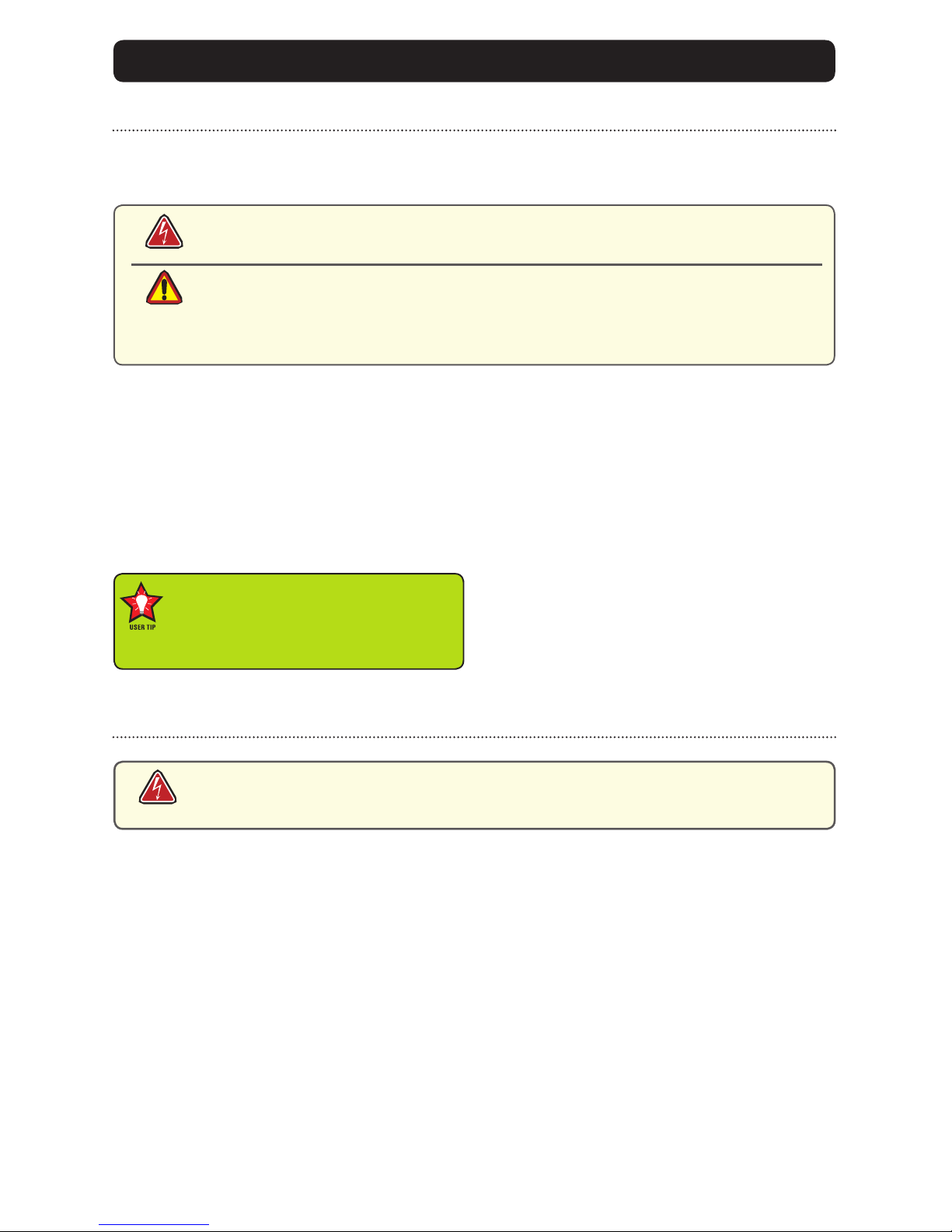
warning!
caution!
Warning! Shock Hazards
This icon is intended to tell you of a potential risk of electrical shock.
Caution! Instructional
This icon is intended to tell you of important operating and/or
Safety Icons
warning!

MPC-MLR-UM(A) 10/2009 7
Electrical Safety
Connecting Cables
• Disconnect the power to the computer when the Monitor is being installed, and
• Upon installation, verify the power connector is securely seated on the unit.
Ratings and Grounding
This unit may be operated from an 8-36 VDC power source.
• Use the supplied power cable, and
• Always connect to a properly grounded power source.
Protection on Servicing
Servicing - User
• User care is limited to cleaning the exterior of the unit.
• Do not disassemble or modify the unit or cables to avoid the possibility of an electrical shock,
damage to electrical components or scratching the Display surface, and
• Disassembly or modication voids the warranty.
Servicing - MarinePC
MarinePC Qualied Service Personnel may be required if the unit:
• Does not operate normally when installation instructions are followed
• Does not operate normally when operating instructions are followed
• Has been dropped or damaged, or
• Exhibits a distinct change in performance, indicating a need for service.
Shipping
If the unit should need to be shipped to the MarinePC Service Center, the original packing mate-
rial should be used to insure safety in shipping. Repack the unit as it would have originally been
received from MarinePC.
Fluids from LCD Display
• If the Monitor should ever become shattered, do not touch uids from an LCD Display
• If uid should get on hands or clothing, immediately wipe o with liquid soap or rubbing
alcohol; wash with water; consult with a doctor, and
• If uid gets in the eyes, ush eyes immediately with water for a minimum of 15 minutes;
This equipment generates, uses and can radiate radio frequency energy. If not
installed with the unit’s accompanying cables, it may cause harmful interference
to radio communications.
Radio Frequency Interterence
caution!
caution!
8MPC-MLR-UM(A) 10/2009
This MPC-MLR Monitor has been designed to provide optimum performance and service without
any required scheduled maintenance other than occasional cleaning.
Display Screen Cleaning
• A vinegar-based cleaner is preferred to prevent streaking and degradation of the
coatings, or
• A non-abrasive glass cleaner such as a professional foam glass cleaner
• Apply the cleaning solution to a soft clean cloth, dampening slightly
• Keep a fresh side of the cleaning cloth towards the screen surface to avoid
scratching it with accumulated grit, and
• To minimize the risk of abrasion to the screen, air drying is recommended.
Disconnect cabling from the Touch Screen Display before cleaning. A Touch Screen
Display will be activated by cleaning the Display. This may create a potentially
dangerous condition.
Optional Touch Screen Cleaning
• Follow cleaning directions above, or use a special screen cleaning tissue or a solution speci-
cally formulated for antistatic coatings.
• Lightly dampen a soft clean cloth with water, vinegar based cleaner or a general purpose mild
detergent solution
• Keep a fresh side of the cleaning cloth towards the screen surface to avoid
scratching it with accumulated grit, and
• To minimize the risk of abrasion to the screen, air drying is recommended.
Monitor Enclosure
• Clean the unit enclosure with a soft clean cloth lightly dampened with a
general purpose mild detergent solution
• To rinse, wipe down with clean water, and
• Dry with a soft clean cloth.
Optional Touch Screen
PRODUCT CARE AND MAINTENANCE
Product Care
• Do not use abrasive cleaners or solvent-based (ammable) cleaners on the
Flat Panel or Touch Screen Display, its enclosure or any other electrical de-
vice (cables, power cord, etc)
• Do not use paper products as they may scratch the Display screen, and
• Do not directly apply cleaning solutions to the Display screen.
Turn o the Monitor power before cleaning the Monitor, optional Touch Screen
or unit’s enclosure.
warning!
caution!
warning!
In marine or similar environments,
an added benet of a vinegar-based
cleaner is its eectiveness in
dissolving salt deposits.

MPC-MLR-UM(A) 10/2009 9
To avoid risk of electrical shock, do not disassemble the unit’s enclosure. Users
cannot service the Monitor. User maintenance is restricted to cleaning, as ex-
plained. Disassembling the unit voids the warranty.
Long-term Storage
• For long-term storage, it is suggested the unit be stored in a normal indoor environment and
the Display glass be protected from accidental damage.
• For pedestal mount units, disconnect the cable(s) and loosen the arm adjustment to
a point where the ball can be removed from the arm, or
• For Flush or Panel Mount units, cover the product with a protective covering that
shall not scratch or transfer any dyes to the Display screen.
Maintenance
Other Maintenance
Only MarinePC Qualied Service Personnel shall perform all maintenance except for
the power cord replacement described above.
To avoid shock and re hazards, replaced the unit’s power cord if:
• Insulation becomes damaged, or
• A loose connection is suspected.
Power Cord
warning!
warning!

10 MPC-MLR-UM(A) 10/2009
SYSTEM SETUP
System Requirements
The computer the MPC-MLR shall be connected to must have this capability:
• Video card setting with a minimum resolution of 640 x 480 pixels, and
• If the optional Touch Screen Display is ordered, an available USB or COM port for the
connector is required.
Shipping Box Contents
The MPC-MLR is shipped in a custom box with custom foam packaging. We
recommend you save the box and all packaging materials in case the unit would
need to be returned to the MarinePC Service Center. (Figure 1)
In the shipping box you shall nd:
• MPC-MLR unit
• Power Cable (Optional)
• VGA Cable (Optional)
• Mounting System and Applicable Hardware
• Touch Screen Cable if the optional Touch Screen is ordered (Optional)
Figure 1

MPC-MLR-UM(A) 10/2009 11
INSTALLATION
The MPC-MLR is designed to be mounted with a universal ball-and-socket mounting kit, or in a
Surface Panel Mount conguration.
Pedestal Mount
The MPC-MLR is shipped with a RAM® universal ball-and-socket system mounting kit (Figure 2).
By installing the Monitor with this kit, the user can quickly adjust the
viewing angle to improve viewability in changing environments. This ball-and-socket
system has proven to be successful in supporting an extreme amount of weight in
high vibration and dicult-mount applications. See Appendix A for link to drawings.
Locate the ball-and-socket system in the shipping box. The kit consists of two RAM
balls on mounting plates and a RAM arm, with an adjustable T-knob and a packet of
three (3) M4 x 10 counter-sunk stainless screws for mounting to the MPC-MLR.
Figure 2
Figure 3 Figure 4
Mounting Holes

12 MPC-MLR-UM(A) 10/2009
There are three mounting holes in the back of the Monitor for the ball mounting plate.
Take care not to strip the screw holes or over tighten. (Figure 4)
• Line up one of the ball mounting plates on these three holes (Figure 4)
• With three (3) M4 x 10 counter-sunk stainless screws attach this mounting plate to the back of
the MPC-MLR.
• Mount the second ball mounting plate where the Monitor shall be installed
• Insert each ball into the RAM arm
• Lightly tighten the arm around the balls using the T-knob on the arm (Figure 2, 4)
• Adjust the Monitor to the viewing preference, and
• Tighten the T-knob to hold the Monitor in position.
It is recommended the remaining ball be mounted on a at surface. Because of the
various surface substrates the Monitor shall be mounted on, the installer shall provide
the screws to mount the other ball.
Surface Panel Mount
The Panel Mount installation should be specied at the
time of order; the ball-and-socket mount system will not be
included in the shipping box.
The mounting hardware packet is included with the unit
accessories in the shipping box. This packet includes four (4)
threaded screws (approximately 7.6 cm [3”] long), four (4)
Nylock nuts and four (4) at washers. For installation, there
are four tapped mounting holes on the four corners of the
unit’s rear panel. The 15”contains 6 each.
It is recommended the installer refer to the mount draw-
ings on MarinePC’s web site, with (link address listed in
Appendix A) for the exact measurements of the unit’s rear
panel pod. These should be helpful when the installer cuts
the required space for the Panel Mount installation.
Take care not to strip the
screw holes or over tighten
as the enclosure is aluminum.
caution!
Figure 5

MPC-MLR-UM(A) 10/2009 13
Power Input
The Power Amphenol Connector is a MIL-DTL-26482
Series I Connector.
• End User supplied or Optional Power Cable
• 3-Pin Connector pin-out is listed in Table 1
• Line up with Connector # 1 in Figure 7
• Add a twist to lock.
DISPLAY CONNECTIONS
1
2
Figure 7
1 Power Input
2 Video Input
1 2
Figure 6
Connectors
There are two (2) MIL-DTL connectors on the MPC-MLR: Power Input and Video Input.
(Figure 6, 7). Connectors are located on bottom of Display housing. From left to right: Power
Input, a 3-Pin Connector and Video Input, a 13-Pin Connector.
Power cable
3-Pin Plug
MIL-C-26482 SERIES I
PIN SIGNAL
A 28 VOLT DC
B 28 VOLT RTN
C CHASSIS_GND
AMPH 71-533721-33P
MATE PT06E833SSR
Table 1
caution!
Use care when inserting or removing connector. Do not force their mating.
MPC-ML8R, -ML10R and -ML12R are listed at 20 Watts maximum.
MPC-15R is listed at 35 Watts maximum.
Power Consumption
warning!

14 MPC-MLR-UM(A) 10/2009
Video Input
The Video Amphenol Connector is a MIL-DTL-38999 Series
I Connector. See Table 2.
• End User supplies Video Cable
• 13-Pin Connector pin-out is listed in Table 2
• Line up with Connector # 2 in Figure 6
• Add a twist to lock.
Table 2
Video cable
13-Pin Plug
MIL-DTL-38999 SERIES I
PIN SIGNAL
1 Red Video Signal
2 Red Video Ground
3 Green Video Signal
4 Green Video Ground
5 Blue Video Signal
6 Blue Video Ground
7 H-SNYC
8 V-SNYC
9 H/V SYNC Ground
10 USB+/RS-232 RXD
11 USB-/RS-232 TXD
12 Digital Ground
13 RI-OUT
AMPH 88-569722-35P
MATE MS27467E11B35S

MPC-MLR-UM(A) 10/2009 15
COMPUTER HOOKUP
Prior to connecting the MPC-MLR to the computer, with another monitor, verify the
computer display properties are set to between 640x480 and 1280x1024 in 4:3 aspect ratio.
• The optimum setting for viewing is 800 x 600 (8.4”) or 1024x768 pixels (all other sizes).
• The refresh rate must be set between 60-75Hz to eliminate screen icker.
• Pixel settings dierent from the native resolution may exhibit less precise images, and
• Pixel settings over 1280 x 1024 ash “out of range”, with no display.
1. Right mouse click on an open area of the
desktop screen to bring up the Desktop Menu.
2. Left mouse click on Properties to
open the Display Properties menu.
3. Connect to a CRT monitor to establish the
computer display properties.
4. Select the Settings tab.
5. Under Screen Resolution, verify
or slide the bar until the Screen
Resolution is at 800 x 600 pixels
(SGVA) or 1024x768(XGA).
6. Select the Advanced button to
go to the next menu to verify the
Hz refresh rate.
Computer Display Properties - XGA or SVGA
Setting the Display Settings
caution!

16 MPC-MLR-UM(A) 10/2009
9. At the Monitor Settings dialog
box, select “Yes” to accept the
new desktop view settings.
10. In the Display Properties dialog
box, verify the Screen Resolution is
at 800 x 600 (SVGA) or 1024x768
(XGA).
11. Select the Apply button.
7. Select the Monitor tab.
8. Under Monitor Settings, verify
the Screen Refresh Rate is
between 60 and 75Hz.
• If so, select the Cancel button
and go to step 9.
• If not, select a setting within
the 60 – 75Hz range
• Select the Apply button.

MPC-MLR-UM(A) 10/2009 17
Power on the Monitor
• The Windows Operating System should automatically apply the best generic driver
for this connection, and
• Follow the instructions under section Computer Display Properties for optimum
display quality.
Signal Quality
• The strength of the video signal provided to the MPC-MLR Monitor has a direct bearing
on the quality of the images displayed
• The cable supplied with the unit shall provide the optimum image if proper
wiring practices are followed
• Install the cable properly and keep it away from sources of EMI such as
electric motors, or unshielded RF sources such as radar and microwaves
• Splitting the video signal also splits the strength of the signal
• If your installation requires more than one Monitor to be driven from a single
video source, it is highly recommended that a video signal booster (line
driver) be used in the circuit, and
• Some splitters are available with an integral line driver. Whether or not a line
driver is used, single cable lengths in excess of our standard cable length
should be of high quality shielded VGA cable.

18 MPC-MLR-UM(A) 10/2009
OPERATOR CONTROLS
On the right hand side of the Monitor bezel
are seven Operator Control buttons.
Power Button
Note: Monitor defaults to an AUTO-OFF state when
power is applied.
• The Power On/O button is marked with
the I/O (Input/Output) symbol
• Momentarily pressing this button shall
turn ON or turn OFF the unit, and
• Blue LEDs glow behind the buttons when
the unit is powered on.
Optional Feature: Monitor defaults to an
AUTO-ON state when power is applied. This
feature must be ordered when the Monitor is
ordered. It is not an add-on after the unit is
built.
Brightness Toggle
This toggle controls the brightness of the LCD Panel Display.
• The large sun toggle side, when repeatedly pressed or held down, shall cause the
Display’s backlight brightness to increase
• The small sun toggle side, when repeatedly pressed or held down can be stepped
down in increments to the lowest setting, which is just above total black and suit-
able in very subdued light, as in night time operations, and
• The Monitor shall revert to a mid-range setting when the unit is powered o.
Select Button
The Select Button is the access point to the On-Screen Display (OSD) Source Screen
Menu. (See On-Screen Display.)
Up Button
The Up Button is an adjustment tool in the OSD Source Screen Menu. (See OSD
Screen Menu Parameters.)
Down Button
The Down Button is an adjustment tool in the OSD Source Screen Menu. (See OSD
Screen Menu Parameters.)
Source Button
The Source Button allows the user to switch between video signal sources attached to the Moni-
tor – Composite Video 1, 2 & 3, and VGA.
Source Select Button
Up Button
Down Arrow
Power On/O (I/O)
Button
Brightness Control Toggle
(large sun, small sun)
Select Button
Adjust the brightness of the Display to the lowest possible setting for
a given set of conditions and display characteristics. Doing so shall
provide the best viewing of the image, extend the lamp life of the
backlight and reduce the internal heat of the Display.

MPC-MLR-UM(A) 10/2009 19
ONSCREEN DISPLAY
The On-Screen Display (OSD) user interface is the path to all display signal source
adjustments. The Source Screen Menu, with its user-friendly graphical interface,
provides access to ne-tuning the Display.
OSD Source Screen Menu Activation
To activate the OSD menu in the current video source, press and release the SELECT
button.
Note: OSD Source Screen Menu shall close after 15 seconds of inactivity. This setting can be
adjusted in the OSD Source Screen Menu (OSD Menu icon), under OSD Duration.
OSD Source Screen Menu Parameters
The Source Screen Menu is comprised of six icons, each representing distinct source
screen categories and their corresponding functions menu with adjustable settings.
Picture Menu Source Menu OSD Menu Set up Menu Inactive OSD Tools Menu
Parameter Adjustments
• To choose a Display Parameter Category, use the UP (right) or DOWN (left) buttons
to move across the Source Screen Menu
• As each Category icon is highlighted, its related Functions Menu appears
in a drop-down box
• To activate a Display Parameter Category, move the highlight box over its icon and
single press the SELECT button
• In the Functions Menu, a highlight bar is superimposed over the rst function
• Press the UP or DOWN buttons to move the highlight bar through the related
Functions Menu
• Single press the SELECT button to choose a Related Functions Menu item when it is
highlighted
• A smiley face appears to the left and a new color bar appears on the Function,
indicating the Category is active; its parameters can be adjusted
• The adjustment controls are the UP and DOWN buttons, which increase or decrease
the value of the parameter as noted in the percentage bar
• Create the new parameter value
• Single press the SELECT button to save the new value; this returns the user to the
Source Screen Menu
• Exit from the Function Menu
• To choose another Display Parameter Category, use the UP (right) or DOWN (left)
buttons to move across the Source Screen Menu and follow the above instructions,
or
• Single press the SELECT button again to exit from the OSD Source Screen Menu, or
• Close the main menu; all changes are saved.

20 MPC-MLR-UM(A) 10/2009
• New settings shall be stored in memory upon pressing the SELECT button to
exit the Source OSD Source Screen Category’s Function Menu.
• If SELECT is not pressed, or inactivity is detected within the 15 second factory
default OSD duration, any function adjustments made shall not be saved.
It is recommended to adjust the LED back light brightness to maximum before
ne-tuning the OSD Source Screen Menu Picture Menu Parameter: Brightness.
Picture Menu Parameters
Brightness
Before adjusting the Brightness function parameters, set the LCD panel backlight
brightness using the control toggle (large sun/small sun); set to its brightest (large sun
button) in the ambient light source.
• Open the “Brightness” function
• Press the UP or DOWN buttons to set the Display’s desired brightness, and
• Adjustments go from very dim (black) to 100%, very bright (dazzling white).
Contrast
Contrast is the dierence in brightness between the light and dark areas of the pixels
of a picture.
• Open the “Contrast” function
• Press the UP or DOWN buttons to set the Display’s desired contrast, and
• Predened minimum to maximum is in the display bar.
Saturation
Saturation is the vividness or intensity of the hue or color.
• Open the“Saturation”function, and
• Press the UP or DOWN buttons to set the Display’s desired saturation.
Tint
Tint is the pinks, blues and greens of the Display.
• Open the “Tint” function
• Press the UP or DOWN buttons to set the Display’s desired tint, and
• Ranges on the Display bar are: low – pinks; mid-range – blues and upper – greens.
Sharpness
• Open the“Sharpness“ function
• Press the UP or DOWN buttons to select a desired sharpness for the Display, and
• Sharpness choices in the Display bar are preset at - 0, 33, 66 and 100%.
Auto Color
• Auto Color is best calibrated from an all-white background. From the VGA video
source, create an all-white background
• Open the“Auto Color“ function
• Press the SELECT button to run the Auto Color Setup. Repeat twice, and
• When complete, press the SELECT button to save the changes and exit.
OSD Source Screen Menu Parameter Selections
caution!
Table of contents
Other Marine PC Monitor manuals


