Marine PC MPC-ML2DVR User manual

MPC-ML2DVR
Digital Video Recorder
LCD Monitor
User Manual
www.MarinePC.com
Programmable

2MPC-ML2DVR-UM(B) 3/2019
Information Disclaimer
This MarinePC User Manual is provided “as-is”, without warranty of any kind, either expressed or implied, includ-
ing but not limited to the implied warranties or merchantability and fitness for a particular purpose.
Documentation Change Notice
The information in this User Manual is subject to change without prior notice in order to improve readability and
reliability as well as design and function. These changes shall be incorporated in a new revision, available from
the product and/or download section of the MarinePC web site, www.marinepc.com.
Liability
In no event shall MarinePC be liable for direct, indirect, special incidental or consequential damages arising out
of the use of or the inability to use MarinePC’s product or its documentation, even if advised of the possibility of
such damages.
Endorsement
Product names mentioned herein are used for identification purposes only and may be trademarks and/or regis-
tered trademarks of their respective companies.
Copyright
This document contains proprietary information protected by copyright. All rights are reserved. No part of this
manual, in whole or part, may be reproduced by any means, in any form, without prior written permission of
MarinePC.
www.marinepc.com
Owner Record
Here is an easy-to-locate form to record the unit’s serial number, and from the invoice,
record the invoice date. The unit’s serial number is located on the back panel.
If the unit ever requires service, please refer to this information when contacting the
MarinePC Service Center.
Product Serial Number Invoice Date
MPC-ML2--DVR ____ / ____ /____

MPC-ML2DVR-UM(B) 3/2019 3
MPC-ML2--DVR
Military Grade
Programmable
Digital Video Recorder
LCD Monitor
8.4”, 10.4”, 12.1”, 15”
User Manual

4MPC-ML2DVR-UM(B) 3/2019
Table of Contents
Introduction.......................................................................................5
General Safety Precautions..............................................................6
Product Care, Maintenance..............................................................8
System Setup and Installation..........................................................9
Display Connectors ........................................................................10
Digital Video Recorder....................................................................13
Media Storage, Video Status Popup Window.................................14
DVR Main Menu .............................................................................15
Power ON View, Video Feed Record Options ...........................15
Main Menu, Video Input Options ...............................................19
Media Menu, Delete, PC Download, Playback..........................22
PIP/POP/QUAD Options ...........................................................29
Save View, Name View Options ................................................32
Optional NVIS Menu..................................................................34
IBIT Menu ..................................................................................35
Utility, Date/Time, Startup Menus ..............................................37
Programmable Softkeys ................................................................43
Communication Protocol ................................................................48
Internal Heater................................................................................60
Appendix A - Mechanical Drawings ................................................61
Appendix B - NEMA and IP Industry Standards .............................61

MPC-ML2DVR-UM(B) 3/2019 5
With the acquisition of an All-Weather Digital Video Recorder/Monitor, MPC-ML2DVR, we
welcome you to MarinePC’s family of ruggedized professional marine grade products.
You will soon become familiar with the quality dierence in this bright sunlight-readable
(~1 nit to 1,000 nits) Monitor, specically designed to meet or exceed MIL-Specs for use
in harsh marine environments. MarinePC has incorporated the latest LED backlighting to
increase brightness and super-low dimming without increased heat, and extends tem-
perature, shock and vibration specications.
The MPC-ML2DVR also integrates full DVR capability directly inside the case of the water-
proof monitor, eliminating separate mounting interconnecting cables, saving space and
providing environmental protection and tranportability for the DVR.
In addition, this new release, Series 2, incorporates user programmable function buttons
conveniently mounted on the bezel to provide customizable multiple functionality in one
ruggedized station.
The MPC-ML2DVR handles a wide-range of severe environments, making it the rst choice
of serious mariners for their demanding applications. Designed to be rugged, the 800x600
(SVGA) up to 1024x768 (XGA) Resolution Flat Panel Display is engineered to mate perfect-
ly to all leading edge cameras including infrared, image amplied and visible spectrum
sources.
Housed in a milled billet aluminum case, the slim-prole MPC-ML2DVR is light weight and
watertight, with fully sealed (IP67) case and standard MIL-C-38999 connectors. Engi-
neered to be energy ecient to conserve power, the MPC-ML2DVR has three Composite
Video inputs, with a source select button that lets you easily move between up to three
inputs, and also provides one video output. Recorded les can be easily downloaded in
standard .wmv le format via a USB connection.
Our MarinePC Service and Support Team is prepared to assist you – we are MarinePC.
Welcome.

6MPC-ML2DVR-UM(B) 3/2019
General Safety Instructions
• BeforeoperatingtheMPC-ML2DVRDisplay,readthisUserManualthoroughly
• KeepthisUserManualforfutureuse
• Verifythesystemcapability(seeSystemSetup)toensureoperationoftheDisplay
• Forexpeditiousinstallation,followtheseUserManualinstructionsinsequence
• AdheretoallCautionandWarningsonsystemandasstatedinthisUserManual
• UserManualinstructionsforinstallationandoperationshouldbefollowedprecisely
• AdjustonlythosecontrolscoveredbythisUserManual’sinstructions;improperadjust-
mentofothercontrolsvoidsDisplay’swarrantyandmayresultinDisplaydamage,and
• Adheretolocalinstallationcodes.
General DISPLAY Safety
• AlwaysdisconnectDisplayfrompowersourcebeforecleaning
• DonotoperateDisplaywithadamagedcable,and
• DonotoperateifDisplayhasbeendroppedordamaged.Unitshouldbeinspectedby
qualiedMarinePCServicePersonnel.
GENERAL SAFETY PRECAUTIONS
• Powercablemustbeconnectedtoaproperlywiredandgroundedpowersource
• AnysystemtowhichtheDisplayisattachedmustalsobeconnectedto
properly wired and grounded power sources
• DonotconnectordisconnectDisplayduringanelectricalstorm
• DonotopenDisplayenclosure–therearenoUserserviceableparts
• DonotdisassembleormodifyDisplaytoavoidpossibilityofelectricalshock,
damage to electrical components or scratching the Display surface, and
• DisassemblyofDisplayvoidswarranty.
Safety Icons
Safetyicons aredisplayedthroughouttheUser Manualtodrawattentionto specicUser
Caution and Warning Instructions.
This icon is intended to tell the User of important operating and/or
maintenance instructions.
This icon is intended to tell the User of a potential risk of electrical shock.
WARNING!SHOCKHAZARDS
CAUTION!INSTRUCTIONAL
GENERAL SAFETY
MPC-ML2DVR-UM(B) 3/2019 7
LCD AND ELECTRICAL SAFETY
LCD Display Safety
It is recommended Users adhere to personal safety in the instance the DVR display screen
shouldbeshattered.Asidefromobviousglassshards,theuidsintheLCDareaknownskin
irritant.
Electrical
Product has been engineered to meet or exceed international industry standards
addressing product design and enclosure protection against EMI/RFI.
FLUIDSFROMLCDDISPLAY
• IfDisplayshouldbecomeshattered,donottouchuidsfromLCDScreen
• Ifuidshouldgetonhandsorclothing,immediatelywipeowithliquidsoap
orrubbingalcoholonacleantowel;washwithwater;immediatelyconsultwith
a doctor, and
• Ifuidgetsintheeyes,usheyesimmediatelywithwaterforaminimumof
15minutes;immediatelyconsultwithadoctor.
EMI/RFI
Connecting Cables
• DisconnectpowertosystemwhenDisplayisbeinginstalled
• Uponinstallation,verifypowerinputconnectorissecurelyseatedonDisplay
• Positionpowercablesoitisnotincontactwithhotsurfaces
• Donotallowanythingtorestonpowercable,and
• Protectpowercablefromextremeheatsources.
Power Source
• AlwaysconnecttoaproperlygroundedDC(standard)powersource
• UnitmaybepoweredwithaqualiedAC/DCAdapter(askfactoryfordetails)
• AnyequipmenttowhichDisplayisattachedmustalsobeconnectedtoprop-
erly wired and grounded power sources
• Operationalvoltageis10-36VDC(Inputis12,24,28VDCnominal),and
• PowerConsumptionis:30Wattsmaximum.
MPC-ML2DVR power consumption is listed at 30 Watts maximum.
POWERCONSUMPTION
8MPC-ML2DVR-UM(B) 3/2019
PRODUCT CARE
This DVR Display has been designed to provide optimum performance and service without
anyrequiredscheduledmaintenanceotherthanoccasionalcleaning.
Display Screen Cleaning
• Avinegar-basedcleanerispreferred:preventsstreaking,degradationofcoatings
• Anonabrasiveglasscleanermaybeused,asinprofessionalfoamglasscleaner
• Applycleaningsolutiontoasoftcleancloth,dampeningslightly
• Keep a fresh side of cleaning cloth towards screen surface to avoid scratching it with
accumulated grit as Display screen is made of glass, and
• Tominimizeriskofabrasiontoglassscreen,airdryingisrecommended.
Display Enclosure
• CleanDisplayenclosurewithsoftcleanclothlightlydampenedwithamilddetergentsolu-
tion
• Wipedownwithcleanwater;drywithasoftcleancloth.
Product Care
• Donotuseabrasiveorsolvent-based(ammable)cleanersonDisplay
enclosureoranyotherelectricaldevice(cables,powercable,etc.)
• DonotusepaperproductsastheymayscratchDisplayscreen,and
• DonotdirectlyapplycleaningsolutionstoDisplayscreen.
Disconnect Display from power source before cleaning Display, optional
TouchScreenorDisplay’senclosure.
Long-term Storage
• Forlong-termstorage,itissuggestedDisplaybestoredinanormalindoorenvironment
and Display glass be protected from accidental damage
• Forpedestalmountunits,disconnectcable(s)andloosenarmadjustmenttoapointwhere
ball can be removed from arm, or
• For Flush or Panel Mount units, cover product with a protective covering that will not
scratch or transfer any dyes to Display screen.
Disassembling Display voids warranty. To avoid risk of electrical shock,
donotdisassembleenclosure;Userscannotservice.Usermaintenance
is restricted to cleaning or power cable replacement, as explained.
In marine or similar environments, a benet of a vinegar-based cleaner
is its eectiveness in dissolving mineral and salt deposits.

MPC-ML2DVR-UM(B) 3/2019 9
MAINTENANCE
POWER CABLE
Maintenance
Other Maintenance
OnlyMarinePCQualiedServicePersonnelshouldperformallothermaintenanceexceptfor
cleaning and power cable replacement as described.
Toavoidshockandrehazards,replacedDisplay’spowercableif:
• Insulationbecomesdamaged,or
• Alooseconnectionissuspected.
Protection on Servicing
Servicing - User
• UserServicingislimitedtocleaningtheDisplay
• DonotdisassembleormodifytheDisplaytoavoidthepossibilityofelectricalshock,
damage to its electrical components or scratching the Display surface, and
• Disassemblyvoidsthewarranty.
Servicing - DSE
MarinePCQualiedServicePersonnelmayberequiredtoservicetheDisplayif:
• Doesnotoperatenormallywheninstallationinstructionsarefollowed
• Doesnotoperatenormallywhenoperatinginstructionsarefollowed
• Hasbeendroppedordamaged,or
• Exhibitsadistinctchangeinperformance,indicatinganeedforservice.
Shipping
If Display should need to be shipped to the MarinePC Service Center, the original packing
material should be used to ensure safety of Display in shipping. Repack Display as it would
have originally been received from manufacturer.
Shipping Box Contents
The DVR is shipped in a custom box with enhanced packaging. Installer should save box and
all packaging materials in the instance Display is returned to the MarinePC Service Center.
Shippingboxcontentsare:
• MPC-ML2DVRDisplay
• CablesandRAMArmMounting,ifOrdered
INSTALLATION
TheDVRcanbeinstalledwith:FrontMount(M4),PanelMount(M4);RAMMount(M4),Side
Mount(M4),orVESAMount(75mm/M4).Followknown-goodpracticesduringinstallation.
SYSTEM SETUP
TheDVRacceptsCompositeVideosignals;(4)RS170Inputs;(1)RS170Output.
10 MPC-ML2DVR-UM(B) 3/2019
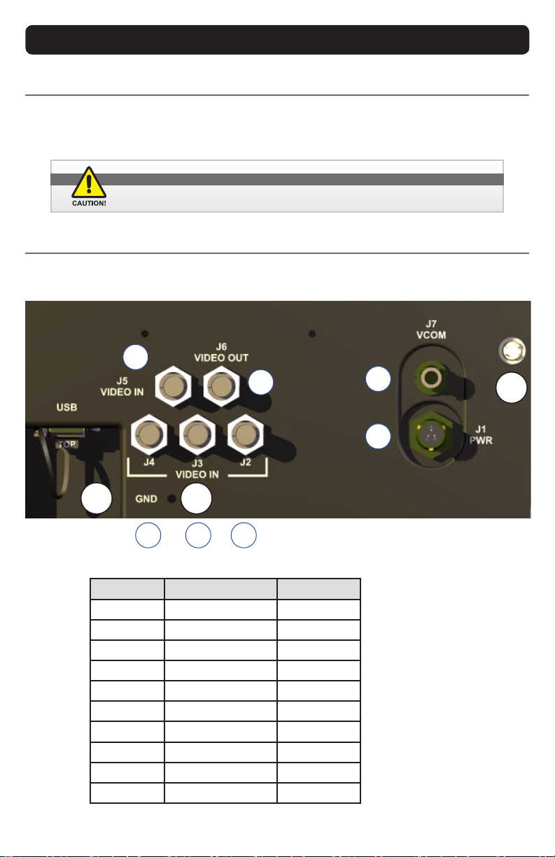
DISPLAY CONNECTORS
Cables
Withawiderangeofsysteminstallationsrequiringvaryingcablelengths,theDVRdoesnot
shipwithcables.Special-ordercablesareavailable;otherwise,allcablesaresuppliedby
the end user.
Connectors are located on the back of the DVR chassis. See Figure 1, Table 1 for Con-
nector Assignments.
Connectors
Use caution when coupling or uncoupling cables and connectors.
POSITION CONNECTOR CALL - OUT
1POWER J1
2VIDEO IN J2
3VIDEO IN J3
4VIDEO IN J4
5VIDEO IN J5
6VIDEO OUT J6
7VCOM J7
PE PRESSURE EQ. N/A
USB USB USB
GND GROUND GND Table 1
Figure 1
1
GND
PE
USB
234
67
5

MPC-ML2DVR-UM(B) 3/2019 11
DISPLAY CONNECTORS CONTINUED
Power Connector (J1)
The military grade sealed Power Connector is J1. See
Table 2.
• Align up with J1 connector; See Figure 1, #1
• Add a twist to lock
• End-user supplies cable
Table 2
POWER CONNECTOR
J1 PWR
PIN SIGNAL
A28 VOLT DC
B28 VOLT RTN
CCHASSIS GROUND
AMPH 71-533721-33P
MATE PT06E-833SSR
BNC CONNECTOR IN
J2 - J5
PIN SIGNAL
1VID_IN
2GROUND
Table 3
Composite - VIDEO IN (J2 - J5)
The center pin BNC Connectors - VIDEO IN (J2-J5) allow input
of auxiliary composite video signals (RS170). See Table 3.
• Align with J2-5, VIDEO IN connector;
See Figure 1: #2 (J2), 3 (J3), 4 (J4), 5 (J5)
• Add a twist to lock
• BNC receptacle is sealed
• End-user supplies cables
Composite - VIDEO OUT (J6)
The center pin BNC Connector - VIDEO OUT (J6) provides
pass-through of composite video signal. See Table 4.
• Align with J6, VIDEO OUT connector; See Figure 1, #6 (J6)
• Add a twist to lock
• BNC receptacle is sealed
• End-user supplies cable
BNC CONNECTOR
OUT
J6
PIN SIGNAL
CENTER VID_OUT
SHELL GROUND
Table 4
12 MPC-ML2DVR-UM(B) 3/2019
DISPLAY CONNECTORS CONTINUED
VCOM (J7)
The VCOM (J7) connector allows for communicaitons with
external device. See Table 5. External communicaiton is only
active when Video Input 1 (J2) is displayed.
• Align with J7 - VCOM connector; See Figure 1, #7 (J7)
• End-user supplies cable
VCOM
J7
PIN SIGNAL
1RS422 TX+ COM
2RS232 TXD COM
3RS232 RXD COM
4DIGITAL GND
5RS422 RX+ COM
6RS422 TX- COM
7RS422 RX- COM
AMPH 803-015-07ZN6-7PN
MATE 803-001-06ZN6-7SN
Table 5
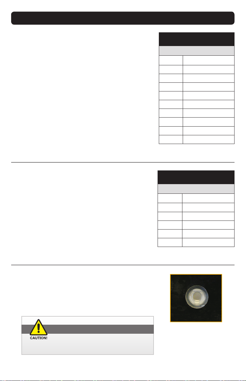
Pressure Equalizer Valve
There is a Pressure Equalizer Valve on the chassis, see Figure 1,
PE. See Figure 2 for close-up. In nal installation, do not block
or constrain valve.
Figure 2
CAUTION!
DonotblockorconstrainthePressureEqualizerValve.
Table 6
USBA CONNECTOR
USB-A
PIN SIGNAL
1N/C
2DATA -
3DATA +
4GND
AMPH P-MUSB-A511-00
USB-A CONNECTOR (USB)
The USB-A Connector (USB) provides the link to download
saved mp4 and jpg les from the Media Library. See Table 6.
• Align with USB connector; See Figure 1, USB
• End-user supplies cable

MPC-ML2DVR-UM(B) 4/2019 13
DIGITAL VIDEO RECORDER (DVR)
TheDigitalVideoRecorder(DVR)capturesreal-timerecordingofhighframe-rate(30fps)
24-bithi-resolutionimagery.Videolesarecompressedinindustry-standardMPEG-4format
(mp4leextension).SnapshotsaresavedinJPEGformat,(jpgleextension).Videoand
SnapshotlesarestoredintheMediaGallery(MediaMenu,Figure13).
DVR Operating Modes. The DVR has two operating modes: Standard (as in Live Video Feed)
and Playback, through Media Gallery viewing. See Media Menu, Figure 13.
RECORD. FromMenuOView(PowerON),selecttheRecordkeytostartaVideoRecording
of the selected Channel Video Input. Videos are saved with the current Time/Date stamp.
Record button is preset and may be moved to another softkey in Program Button set-up
(SeeUtility Menu,Figure 27). The DVR stops recording when User is in the Media Menu
(Figure 13).
• Single Source Layout. Recording Starts/Stops with key press
• PIP Layout. RecordVideoInputSourcesavedinPIPOptions(Figure20)isdefault
forrecording;PIPRecordMenuopens(Figure8).SavestoMediaGallery(Figure13)
• POP Layout. Recording in Picture-Over-Picture mode is not available
• QUAD Layout. InputSourceChannelRecordsavedinQUADOptionsMenu(Figure
22)isdefaultfor recording; QUAD RecordMenuopens(Figure 10). Saves toMedia
Gallery(Figure13)
STOP RECORDING. To STOP a Recording, press the RECORD button to stop the process.
SNAPSHOT. Takes a Snapshot (jpg) of Video Input Source image in view. Opens up the
SnapshotViewerMenu(Figure19).SnapshotimageissavedtotheMediaGallery(Media
Menu,Figure13)withthecurrentTime/Datestampofrecording.Snapshotsmaybetaken
ofaVideoimage.Snapshot(SNAP)ispresetandmaybemovedtoanothersoftkeyinthe
ProgrammableButtonset-up.(Toaccess,seeUtilityMenu,Figure27).
VIDEO RECORDING TIME. For full motion, full color feed, NTSC recording time is approximately
1GB/hour. PAL recording time is just over 2GB/hour. Black and white feed (i.e. Infrared (IR) Camera)
and/or lesser bandwidth signals should result in Media storage using less than 1GB/hour for NTSC,
and less than 2GB/hour for PAL.
MEDIA FILE NAMES. Video or Snapshot File names reference Military naming format: YY-
MM-DD_HR_MN_SEC. Example: January 15, 2016, 9:15.47 AM Video Recording is read as 16-
01-15_09-15-47.mp4. File names are readable when Display is connected to a PC and viewed as
a remote disk drive. When the USB is connected Windows will recognize the display as a storage
device. However, the PSM must be in download mode rst (PC Download Menu, Figure 16).
DVR STOPS RECORDING WHEN USER IS IN MEDIA LIBRARY MENU.
14 MPC-ML2DVR-UM(B) 3/2019
MEDIA STORAGE
MEDIA FILE STORAGE CAPACITY. Total Media File Storage Capacity is based on memory GB in-
stalled. Memory is not eld-upgradeable or replaceable. If display’s memory capacity is unknown,
User may determine capacity when display is connected to a PC for Media Gallery PC Download
(Figure 16).
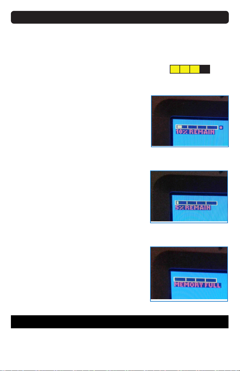
Media Memory STATUS BAR
In the upper left of the display screen, a yellow Recording
Media Memory Status Bar Indicator depicts available DVR
recording memory. (Figure 3). This yellow bar decreases as
DVR storage memory is lled. Note that the Bar Indicator
disappears in Media Menu (Figure 10) as recording is not
available at that point. ARed Dot Indicator, placed to the
right of the Available Media Storage Bar, ashes when DVR
is recording (Figure 4).
AVAILABLE Memory BAR
When 10% of available Recordable Media Storage is re-
maining, a 10% REMAIN message appears under the Media
Storage Bar (Figure 4). When 5% of available Recordable
Media Storage is remaining, a 5% REMAIN message ap-
pears (Figure 5).
Memory full
Memory Full is reported when there is no free memory in
the storage device. If there is a failure of the DVR to delete
the oldest le while performing Continuous Recording, a
MEMORY FULL message will appear under the Storage In-
dicator Bar (Figure 6).
OPTIONAL CONTINUOUS RECORDING
The Display may have been ordered with a Continuous
Recording option, meaning DVR Media Storage will de-
lete approximately 1GB of the oldest Media les (Videos or
Snapshot images) from the Media Storage System to pro-
vide memory space for new recordings.
When the oldest Media les are deleted, a warning mes-
sage posts: ‘Continuous Recording. Old les deleted.’ If
there is a failure of the DVR to delete the oldest le and per-
form Continuous Recording, a MEMORY FULL message will
appear under the Storage Indicator Bar. Memory Full is re-
ported when there is no free memory in the storage device.
Recording stops when user is in Media Menu.
Figure 4. FLASHING red dot (Record-
ing), 10% Remain message
Figure 5. Not in record mode (no red
dot) , 5% Remain message
Figure 6. Memory full message
Figure 3. Bar Indicator;
25% used
In the bottom center of the screen, a popup information window (aka ‘toast’) displays the video
status as it changes. It will list both physical port and resolution (or no video) detected, then close
after approximately 5 seconds.
VIDEO STATUS POPUP WINDOW

MPC-ML2DVR-UM(B) 3/2019 15
SRC
B1 B2 B3 B4 B5
L1
L2
L3
L4
L5
R1
R2
R3
R4
R5
T1 T2 T3 T4 T5
Figure 7
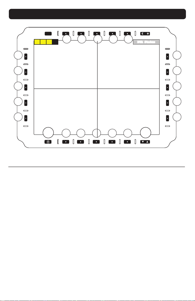
Select POWER ONbutton(PWR)(bottomleft)toPowerONDisplay.Rapidpowercycling
(ON/OFF/ON)isnotsupported.MenuOView(Figure7)appears;defaultprogrammable
bezelkeysarelabeled.OtherbezelkeysareprogrammedandlabeledbyUser.(SeeUtility
Menu,Figure27,forsubmenuaccess).
MEMORY STATUS. In top left, Memory Status icon indicates Available Recording Memory.
YellowbardisappearsasMemoryllsup.Exampleshows75%freespace.
DVR STATUS. DVRStatusdisplaysintopright:‘DVRInitializing’,‘DVRError’or‘DVR
Recording’.
DVR ERR, PLEASE CYCLE PWR. Error message DVR ERR, PLEASE CYCLE PWR will post across
screen if DVR is not working properly. Unit has to go through Power Cycle (reboot) to reset DVR.
POWER DOWN. Hold Power (PWR) button for a few seconds to Power DOWN. At
PowerDOWN,inupperleftscreen,DVRstatusreads‘DVRSHUTTINGDOWN’.IfDVR
wasinrecordmode,leissavedandlenameissplashedacrossbottomofscreen.
REC. Starts recording of selected input feed and opens the RECORD menu. When pressed,
text(andaction)togglesbetweenRecordandStop.RedDotflashes when DVR is recording.
MEDIA. Opens Media Menu, Figure 13.
SNAPSHOT. Takes a Snapshot of selected input feed.
Menu o VIEW (Power ON view)
MENU OFF VIEW
DVR INITIALIZING
Figure 7. MENU OFF VIEW
PWR
REC (STOP) SNAPSHOT
MEDIA

SRC
B1 B2 B3 B4 B5
L1
L2
L3
L4
L5
R1
R2
R3
R4
R5
T1 T2 T3 T4 T5
16 MPC-ML2DVR-UM(B) 3/201B
PICTURE-IN-PICTURE (PIP) RECORD MENU
Picture-in-Picture(PIP)RecordMenu oers a channel feedsuperimposedoverasecond
channelfeedthatstretchesacrossthescreen(Figure8).Bydefault,PIPboxisintheupper
leftscreenandmaybemovedintheUtilityMenu(Figure27).Ahighlightborderisdrawn
aroundfeedthatwillberecorded.Channelpositions(PIPorMain)anddefaultchannelfor
VideorecordingaresetinVideoModeMenu(Figure12).Onlytheselecteddefaultchannel
feed is recorded. Videos/Images are saved in the Media File with current Time/Date stamp.
Only (1) Video Input Source may be recorded at a time; a Border draws around the recorded
feed.
MEMORY STATUS. Top left Memory Status Bar indicates available memory for record-
ing to the Media Gallery. Yellow indicate storage remaining. When Memory is full, MEMORY
FULL-UNABLETOREC(ORD)replacestheMemoryStatusbar.
DVR STATUS. Initializing,DVRErrororRecordingStatusdisplaysintopright.
REC CHX (L1). Sets CHX as record path Video Input Source and closes Record Menu.
CHXwilldisplay(C1,C2,C3orC4)tomatchcurrentPIPVideoInputSource.Settingholds
through power cycles.
REC CHY (L5). Sets CHY as record path Video Input Source and closes Record Menu.
CHYwilldisplay(C1,C2,C3orC4)tomatchcurrentBackgroundVideoInputSource.Set-
ting holds through power cycles.
STOP (B5). Stops recording and closes the Record Menu.
Figure 8. Pip RECORD MENU
PIP
(C1, C2, C3 or C4)
PICTUREINPICTURE PIP RECORD MENU
BACKGROUND (C1, C2,
C3 or C4)
DVR Status
PWR
REC CHX
REC CHY
STOP

MPC-ML2DVR-UM(B) 3/2019 17
SRC
B1 B2 B3 B4 B5
L1
L2
L3
L4
L5
R1
R2
R3
R4
R5
T1 T2 T3 T4 T5
PICTUREOVERPICTURE POP RECORD MENU
PICTURE-OVER-PICTURE (POP) RECORD MENU
Picture-Over-Picture (POP) Record Menu oers a view with a two-channel view splitting
thescreenhorizontally(Figure9).Channelpositions(toporbottom)anddefaultchannel
forVideorecordingaresetintheVideoModeMenu(Figure12).Onlytheselecteddefault
channel feed is recorded, not both channel feeds. Videos/Images are saved in the Media
File with the current Time/Date stamp.
Recording in Picture-Over-Picture mode is not available; only the default channel will record.
Only (1) Video Input Source may be recorded at a time; a Border draws around the recorded
feed.
MEMORY STATUS. Top left Memory Status Bar indicates available memory for record-
ing to the Media Gallery. Yellow indicate storage remaining. When Memory is full, MEMORY
FULL-UNABLETOREC(ORD)replacestheMemoryStatusbar.
DVR STATUS. Initializing,DVRErrororRecordingStatusdisplaysintopright.
REC CHX (L1). Sets CHX as record path Video Input Source and closes Record Menu. CHX
willdisplay(C1,C2,C3orC4)tomatchtopPOPsource.Settingholdsthroughpowercycles.
REC CHY (L5). Sets CHY as record path Video Input Source and closes Record Menu.
CHXwilldisplay(C1,C2,C3orC4)tomatchbottomPOPVideoInputSource.Settingholds
through power cycles.
STOP (B5). Stops recording and closes the Record Menu.
Figure 9. Pop RECORD MENU
(C1, C2, C3 or C4)
(C1, C2, C3 or C4)
DVR Status
PWR
REC CHX
REC CHY
STOP
SRC
B1 B2 B3 B4 B5
L1
L2
L3
L4
L5
R1
R2
R3
R4
R5
T1 T2 T3 T4 T5
18 MPC-ML2DVR-UM(B) 3/2019
PWR U/D
QUAD RECORD MENU
QUAD RECORD MENU
TheQUADRecordMenuoersviewingfromfourindependentVideofeeds(Figure10).The
screenisdividedintofourequalparts.Ahighlightborderisdrawnaroundrecordedfeed,set
inVideoModeMenu(Figure12).Videos/ImagesaresavedwithcurrentTime/Datestamp.
Only (1) Video Input Source may be recorded at a time; a Border draws around the recorded
feed.
MEMORY STATUS. Top left Memory Status Bar indicates available memory for record-
ing to the Media Gallery. Yellow indicate storage remaining. When Memory is full, MEMORY
FULL-UNABLETOREC(ORD)replacestheMemoryStatusbar.
DVR STATUS. Initializing,DVRErrororRecordingStatusdisplaysintopright.
REC CH1 (L1). Sets CH1 as recording path Video Input Source and closes Record Menu.
REC CH2 (R1). Sets CH2 as recording path Video Input Source and closes Record Menu.
REC CH3 (L5). Sets CH3 as recording path Video Input Source and closes Record Menu.
REC CH4 (R5). Sets CH4 as recording path Video Input Source and closes Record Menu.
STOP (B5). Stops recording and closes the Record Menu.
STOP
REC CH3
REC CH1
C1
C3
C2
C4
REC CH2
REC CH4
Figure 10. QUAD RECORD MENU
DVR Status
MPC-ML2DVR-UM(B) 3/2019 19
SRC
B1 B2 B3 B4 B5
L1
L2
L3
L4
L5
R1
R2
R3
R4
R5
T1 T2 T3 T4 T5
MAIN MENU ACCESS
The Main Menu is the entry portal to submenus. The following submenus are accessed,
which open additional tiers of submenus.
VIEW MODE (L1). EnterViewModesubmenu(Figure12).
MEDIA (L2). AccesstotheMediaGallery(Figure13),athumbnailgridofrecordedVideo
andSnapshotles.
IBIT (L3). EnterInitiateBuilt-In-Test(IBIT)menu(Figure26).Checkssystemfunctionality.
NVIS SETTINGS (L4). (Optionalfeature).EnterNVISSettingssubmenu(Figure25).
UTILITY (R1). EnterUtility(Tools)submenu(Figure27).(FactoryReset,Programmable
Buttons,ButtonText,Startup,J7VCOMMenu.)
EXIT (R5). ReturnstoMenuOFF(PowerON)view(Figure7).
Main Menu
Several User Menus are available in the PSM. The Main Menu is a starting point to access
thePSM’ssubmenus(Figure11).HolddowntheSRC(SOURCE)keyforthree(3)seconds
(toprow,farleft)toaccesstheMainMenufromanyothermenuscreen.
SOURCE button (SRC) is on top row left. From other menu
screens,holddownfor(3)secondstoreturntoMainMenu.
MAIN MENU
Figure 11. Main MENU
VIEW MODE
NVIS SETTINGS (OPTIONAL)
IBIT MENU
UTILITY
EXIT
MEDIA
20 MPC-ML2DVR-UM(B) 3/2019
SRC
B1 B2 B3 B4 B5
L1
L2
L3
L4
L5
R1
R2
R3
R4
R5
T1 T2 T3 T4 T5
VIEW MODE MENU
The View Mode Menu is where Video View settings are assigned to each physical connector,
andthatVideofeed(Figure12).Eachchannelviewsettingisindependentofeachother.
View Mode Menu is accessed from L1 in the Main Menu (Figure 11). Access the Video
Channelfeedsthrough the ‘B’(Bottom) softkeys,thenset VideoScalingOption (R2 - 4).
Channeldisplayedinbracketisthedefaultfeed.Example:[C4].
Only (1) Video Input Source may be recorded at a time; a Border draws around the recorded
feed.
Video MODE SELECTIONS
C1 (B1). Edit Composite 1 Video options.
C2 (B2). Edit Composite 2 Video options.
C3 (B3). Edit Composite 3 Video options.
C4 (B4). Edit Composite 4 Video options.
INPUT OP/OFF (R1). Enables or Disables Video Input for Source (SRC) button selection.
PIP (R2).Select to entersubmenuPicture-In-Picture(PIP)layoutoptions(Figure8).
POP (R3).Select to entersubmenuPicture-Over-Picture(POP)layoutoptions(Figure9).
QUAD (R4). Select to entersubmenuQUADlayoutoptions(Figure10).
BACK (R5).ReturnstoMainMenu(Figure11).
Figure 12. VIEW MODE MENU
VIEW MODE MENU
BACK
C1 C2 C3 C4
A
B
P
I
P
A
B
P
O
P
CD
B
A
Q
U
A
D
INPUT (ON/OFF)
PIP
POP
QUAD
Other manuals for MPC-ML2DVR
1
Table of contents
Other Marine PC Monitor manuals


