Marine PC MIL-Spec MPC-ML2 D Series User manual
MPC-ML2xxD
MIL-Spec
LCD Displays
User Manual
www.MarinePC.com
N
S
E
W
MARINE PC
MARINE PC

Information Disclaimer
This MarinePC User Manual is provided“as-is”, without warranty of any kind, either expressed or implied,
including but not limited to the implied warranties or merchantability and fitness for a particular purpose.
Documentation Change Notice
The information in this User Manual is subject to change without prior notice in order to improve readability
and reliability as well as design and function. These changes shall be incorporated in a new revision, available
from the product and/or download section of the MarinePC web site, www.marinepc.com.
Liability
In no event shall MarinePC be liable for direct, indirect, special incidental or consequential damages arising out
of the use of or the inability to use MarinePC’s product or its documentation, even if advised of the possibility
of such damages.
Endorsement
Product names mentioned herein are used for identification purposes only and may be trademarks and/or regis-
tered trademarks of their respective companies.
Copyright
This document contains proprietary information protected by copyright. All rights are reserved. No part of this
manual, in whole or part, may be reproduced by any means, in any form, without prior written permission of
MarinePC.
www.marinepc.com
Owner Record
Here is an easy-to-locate form to record the unit’s serial number, and from the invoice,
record the invoice date. The unit’s serial number is located on the back panel.
If the unit ever requires service, please refer to this information when contacting the
MarinePC Service Center.
Product Serial Number Invoice Date
MPC-ML2__D ____ / ____ /____

MPC-ML2D-UM(B) 10/2015
Product Serial Number Invoice Date
MPC-ML2__D ____ / ____ /____
MPC-ML2xxD
Military Grade
All-Weather
LCD Displays
User Manual
www.MarinePC.com

4MPC-ML2D-UM(B) 10/2015
Table of Contents
Introduction................................................................................................................................. 5
Safety.............................................................................................................................................. 6
Product Care and Maintenance............................................................................................ 8
System Set-up...........................................................................................................................10
Installation................................................................................................................................. 11
Cable Connections..................................................................................................................13
Computer Hook-up ................................................................................................................15
Operator Controls ...................................................................................................................18
On-Screen Display (OSD)......................................................................................................19
Optional USB Pass-Through................................................................................................ 23
Optional Touch Screen Display.......................................................................................... 24
Appendix A - Mechanical Drawings ................................................................................31
Appendix B - Troubleshooting........................................................................................... 31
Appendix C -Technical/Environmental Specications...............................................34
MPC-ML2D-UM(B) 10/2015 5
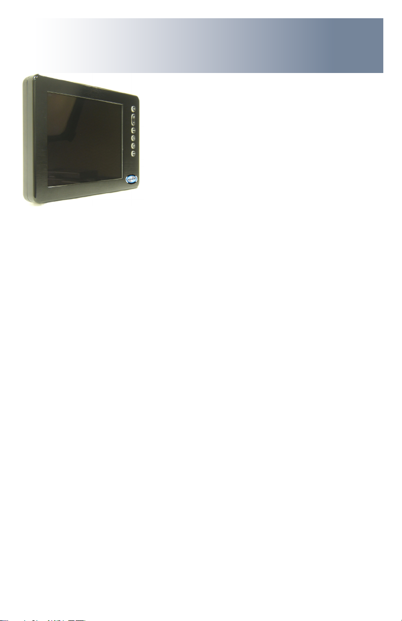
The Marine PC MIL-Spec Monitor (MPC-ML2D) is a ruggedized marine grade LCD Dis-
play for use with a digital video (DVI-D) computer input. It is designed to operate
under the most extreme environments found in high performance vessels such as
public safety, government and military marine craft, as well as submarine vessels. The
ruggedized displays are capable of operating in environments that include extended
temperatures, extreme shock and vibration, direct exposure to salt water and other
environmental conditions.
Housed in a milled billet aluminum case, the slim-prole MPC-ML2D is light weight and
watertight, with fully sealed, military grade connectors. Front-mounted controls and
various mounting options makes the MPC-ML2D user-friendly.
You will soon become familiar with the quality dierence in this bright sunlight-read-
able Display (MIL-L-85762A, MIL-PRF-22885G compliant). The MPC-MLD incorporates
the latest optical engineering to achieve optimal viewability in all lighting conditions.
Engineered to operate on low power consumption, the MPC-ML2D manages a DVI-D
(computer) video input signal. The MPC-ML2D may be equipped with optional Analog
Resistive Touch Screen. This Manual contains instructions for conguring the touch
screen as well.
Our MarinePC Service and Support Team is prepared to assist you – we are MarinePC.
Welcome.

6MPC-ML2D-UM(B) 10/2015
Safety
General Safety Instructions
sequence presented
precisely
adjustment of other controls voids the unit’s warranty and may result in unit damage, and
General Unit Safety
-
ed MarinePC Service Personnel
General Safety Precautions
wired and grounded power sources
damage to electrical components or scratching the Display surface, and
WARNING!
CAUTION!
Warning! Shock Hazards
This icon is intended to tell you of a potential risk of electrical shock.
Caution! Instructional
This icon is intended to tell you of important operating and/or
Safety Icons
WARNING!
MPC-ML2D-UM(B) 10/2015 7
Electrical Safety
Connecting Cables
Ratings and Grounding
Protection on Servicing
Servicing - User
damage to electrical components or scratching the Display surface, and
Servicing - MarinePC
MarinePC Qualied Service Personnel may be required if the unit:
Shipping
If the unit should need to be shipped to the MarinePC Service Center, the original packing mate-
rial should be used to insure safety in shipping. Repack the unit as it would have originally been
received from MarinePC.
This equipment generates, uses and can radiate radio frequency energy. If not
installed with the unit’s accompanying cables, it may cause harmful interference
to radio communications.
CAUTION!
CAUTION!

8MPC-ML2D-UM(B) 10/2015
This MPC-MLD Monitor has been designed to provide optimum performance and service without
any required scheduled maintenance other than occasional cleaning.
Display Screen Cleaning
coatings, or
scratching it with accumulated grit, and
Disconnect cabling from the Touch Screen Display before cleaning. A Touch Screen
Display will be activated by cleaning the Display. This may create a potentially
dangerous condition.
Optional Touch Screen Cleaning
-
cally formulated for antistatic coatings.
detergent solution
scratching it with accumulated grit, and
Monitor Enclosure
general purpose mild detergent solution
Optional Touch Screen
PRODUCT CARE AND MAINTENANCE
Product Care
-
vice (cables, power cord, etc)
or unit’s enclosure.
WARNING!
CAUTION!
WARNING!
In marine or similar environments,
an added benet of a vinegar-based
dissolving salt deposits.

MPC-ML2D-UM(B) 10/2015 9
To avoid risk of electrical shock, do not disassemble the unit’s enclosure. Users
cannot service the Monitor. User maintenance is restricted to cleaning, as ex-
plained. Disassembling the unit voids the warranty.
Long-term Storage
the Display glass be protected from accidental damage.
a point where the ball can be removed from the arm, or
shall not scratch or transfer any dyes to the Display screen.
Maintenance
Other Maintenance
Only MarinePC Qualied Service Personnel shall perform all maintenance except for
the power cord replacement described above.
To avoid shock and re hazards, replaced the unit’s power cord if:
Power Cord
WARNING!
WARNING!

10 MPC-ML2D-UM(B) 10/2015
SYSTEM SETUP
System Requirements
The computer the MPC-MLD shall be connected to must have this capability:
connector is required.
Shipping Box Contents
The MPC-MLD is shipped in a custom box with custom foam packaging. We
recommend you save the box and all packaging materials in case the unit would
need to be returned to the MarinePC Service Center.
In the shipping box you shall nd:

MPC-ML2D-UM(B) 10/2015 11
INSTALLATION
The MPC-MLD is designed to be mounted with a universal ball-and-socket mounting kit, or in a
Surface Panel Mount conguration.
Pedestal Mount
By installing the Monitor with this kit, the user can quickly adjust the
viewing angle to improve viewability in changing environments. This ball-and-socket
system has proven to be successful in supporting an extreme amount of weight in
Locate the ball-and-socket system in the shipping box. The kit consists of two RAM
balls on mounting plates and a RAM arm, with an adjustable T-knob and a packet of
three (3) M4 x 10 counter-sunk stainless screws for mounting to the MPC-MLD.
Mounting Holes
12 MPC-ML2D-UM(B) 10/2015
There are three mounting holes in the back of the Monitor for the ball mounting plate.
the MPC-MLD.
various surface substrates the Monitor shall be mounted on, the installer shall provide
the screws to mount the other ball.
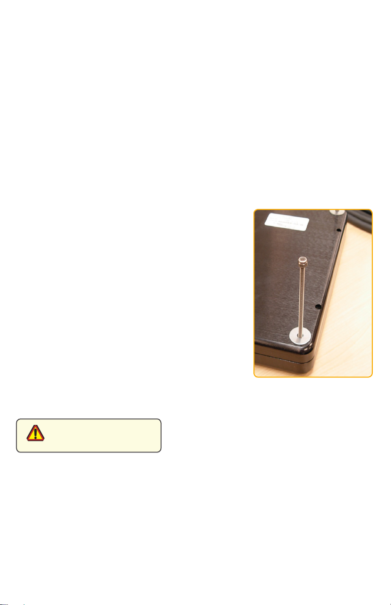
Surface Panel Mount
The Panel Mount installation should be specied at the
included in the shipping box.
The mounting hardware packet is included with the unit
accessories in the shipping box. This packet includes four (4)
threaded screws (approximately 7.6 cm [3”] long), four (4)
are four tapped mounting holes on the four corners of the
unit’s rear panel. The 15” contains 6 each.
It is recommended the installer refer to the mount draw-
ings on MarinePC’s web site, with (link address listed in
Appendix A) for the exact measurements of the unit’s rear
panel pod. These should be helpful when the installer cuts
the required space for the Panel Mount installation.
Take care not to strip the
screw holes or over tighten
as the enclosure is aluminum.
CAUTION!
MPC-ML2D-UM(B) 10/2015 13
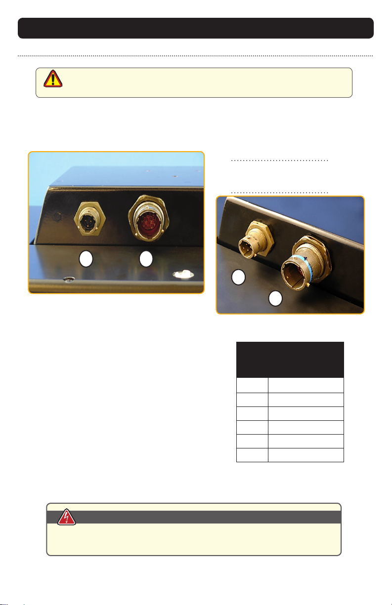
Power Input
The Power Amphenol Connector is a MIL-DTL-26482
Series I Connector.
DISPLAY CONNECTIONS
1
2
1 Power Input
2 Input
1 2
Connectors
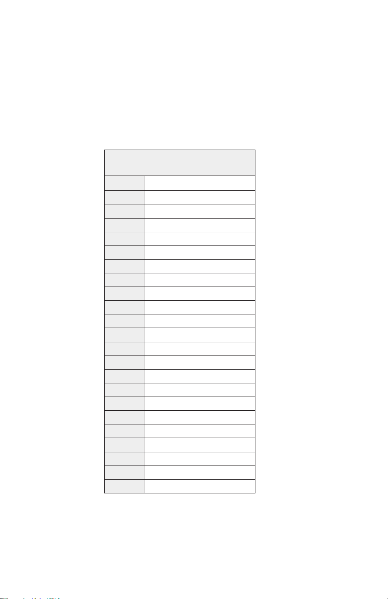
POWER CABLE
3PIN PLUG
MIL-C-26482 SERIES I
PIN SIGNAL
A
B
CCHASSIS_GND
AMPH 71-533721-33P
MATE PT06E833SSR
Table 1
CAUTION!
Use care when inserting or removing connector. Do not force their mating.
MPC-ML8D, -ML10D and -ML12D are listed at 20 Watts maximum.
MPC-15D is listed at 35 Watts maximum.
Power Consumption
WARNING!
14 MPC-ML2D-UM(B) 10/2015
DVI-D
J2 19-PIN PLUG
PIN SIGNAL
1DVI RX2+
2DVI RX2-
3DVI RX1+
4USBD0+/RS232 RXD
5USBD0-/RS232 TXD
6DVI RX1-
7GROUND
8REMOTE ON/OFF (OPTIONAL)
9GROUND
10 DVI +5V
11 DVI RX0+
12 DVI RX0-
13 DVI HOT PLUG DETECT
14 DVI DDC SDA
15 DVI RXC+
16 GROUND
17 DVI DDC SCL
18 GROUND
19 DVI RXC-
AMPH# 2M803-005-07NF9-19PN
MATE# 2M803-002-06NF9-19SN
STRAIN# 390MS137NF0908-xx
MPC-ML2D-UM(B) 10/2015 15
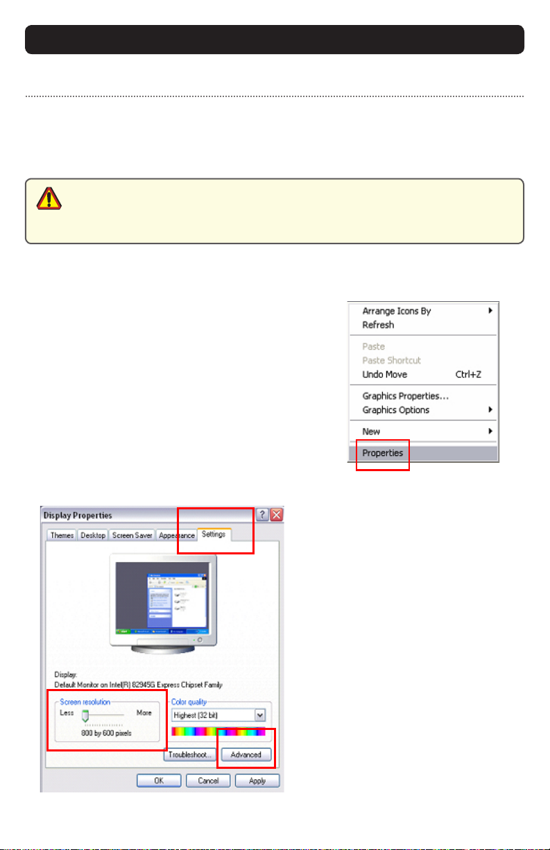
Prior to connecting the MPC-MLD to the computer, with another monitor, verify the
computer display properties are set to between 640x480 and 1280x1024 in 4:3 aspect ratio.
1. Right mouse click on an open area of the
desktop screen to bring up the Desktop Menu.
2. Left mouse click on Properties to
open the Display Properties menu.
3. Connect to a CRT monitor to establish the
computer display properties.
4. Select the Settings tab.
5. Under Screen Resolution, verify
or slide the bar until the Screen
Resolution is at 800 x 600 pixels
6. Select the Advanced button to
go to the next menu to verify the
Hz refresh rate.
Computer Display Properties -
Setting the Display Settings
CAUTION!
16 MPC-ML2D-UM(B) 10/2015
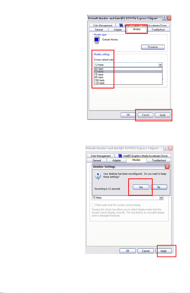
9. At the Monitor Settings dialog
box, select “Yes” to accept the
new desktop view settings.
10. In the Display Properties dialog
box, verify the Screen Resolution is
11. Select the Apply button.
7. Select the Monitor tab.
8. Under Monitor Settings, verify
the Screen Refresh Rate is
between 60 and 75Hz.
and go to step 9.

MPC-ML2D-UM(B) 10/2015 17
Power on the Monitor
for this connection, and
display quality.
Signal Quality
-
ing on the quality of the images displayed
wiring practices are followed
video source, it is highly recommended that a video signal booster (line
driver) be used in the circuit, and
is used, single cable lengths in excess of our standard cable length should be of high
18 MPC-ML2D-UM(B) 10/2015
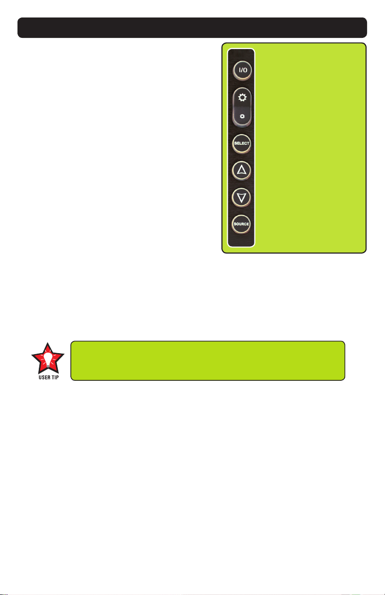
OPERATOR CONTROLS
On the right hand side of the Monitor bezel
are seven Operator Control buttons.
Power Button
power is applied.
the I/O (Input/Output) symbol
the unit is powered on.
Monitor defaults to an
AUTO-ON state when power is applied. This
feature must be ordered when the Monitor is
ordered. It is not an add-on after the unit is
built.
Brightness Toggle
This toggle controls the brightness of the LCD Panel Display.
Display’s backlight brightness to increase
down in increments to the lowest setting, which is just above total black and suit-
able in very subdued light, as in night time operations, and
Select Button
The Select Button is the access point to the On-Screen Display (OSD) Source Screen
Menu. (See On-Screen Display.)
Up Button
The Up Button is an adjustment tool in the OSD Source Screen Menu. (See OSD
Screen Menu Parameters.)
Down Button
The Down Button is an adjustment tool in the OSD Source Screen Menu. (See OSD
Screen Menu Parameters.)
Source Button
The Source Button allows the user to switch between video signal sources attached to the Moni-
Source Select Button
Up Button
Down Arrow
Button
Brightness Control Toggle
(large sun, small sun)
Select Button
Adjust the brightness of the Display to the lowest possible setting for
a given set of conditions and display characteristics. Doing so shall
provide the best viewing of the image, extend the lamp life of the
backlight and reduce the internal heat of the Display.
MPC-ML2D-UM(B) 10/2015 19
ONSCREEN DISPLAY
The On-Screen Display (OSD) user interface is the path to all display signal source
adjustments. The Source Screen Menu, with its user-friendly graphical interface,
provides access to ne-tuning the Display.
OSD Source Screen Menu Activation
To activate the OSD menu in the current video source, press and release the SELECT
button.
Note: OSD Source Screen Menu shall close after 15 seconds of inactivity. This setting can be
adjusted in the OSD Source Screen Menu (OSD Menu icon), under OSD Duration.
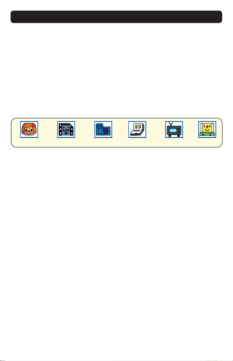
OSD Source Screen Menu Parameters
The Source Screen Menu is comprised of six icons, each representing distinct source
screen categories and their corresponding functions menu with adjustable settings.
Picture Menu Source Menu OSD Menu Set up Menu Inactive OSD Tools Menu
Parameter Adjustments
to move across the Source Screen Menu
in a drop-down box
single press the SELECT button
highlighted
the value of the parameter as noted in the percentage bar
Source Screen Menu
buttons to move across the Source Screen Menu and follow the above instructions,
or

20 MPC-ML2D-UM(B) 10/2015
default OSD duration, any function adjustments made shall not be saved.
It is recommended to adjust the LED back light brightness to maximum before
ne-tuning the OSD Source Screen Menu Picture Menu Parameter: Brightness.
Picture Menu Parameters
Brightness
Before adjusting the Brightness function parameters, set the LCD panel backlight
button) in the ambient light source.
Contrast
of a picture.
Saturation
Saturation is the vividness or intensity of the hue or color.
Tint
Tint is the pinks, blues and greens of the Display.
Sharpness
Auto Color
source, create an all-white background
OSD Source Screen Menu Parameter Selections
CAUTION!
Table of contents
Other Marine PC Monitor manuals


