Marine PC MPC-AWM3V User manual

MPC-AWM3V
All-Weather
LCD Displays
User Manual
www.MarinePC.com
N
S
E
W
MARINE PC
MARINE PC
Information Disclaimer
This MarinePC User Manual is provided“as-is”, without warranty of any kind, either expressed or implied, including but not
limited to the implied warranties or merchantability and fitness for a particular purpose.
Documentation Change Notice
The information in this User Manual is subject to change without prior notice in order to improve readability and reliability
as well as design and function. These changes shall be incorporated in a new revision, available from the product and/or
download section of the MarinePC web site, www.marinepc.com.
Liability
In no event shall MarinePC be liable for direct, indirect, special incidental or consequential damages arising out of the use of
or the inability to use MarinePC’s product or its documentation, even if advised of the possibility of such damages.
Endorsement
Product names mentioned herein are used for identification purposes only and may be trademarks and/or registered trade-
marks of their respective companies.
Copyright 2011
This document contains proprietary information protected by copyright. All rights are reserved. No part of this manual, in
whole or part, may be reproduced by any means, in any form, without prior written permission of MarinePC.
www.marinepc.com
Owner Record
Here is an easy-to-locate form to record the unit’s serial number, and from the invoice, record the
invoice date. The unit’s serial number is located on the back panel.
If the unit ever requires service, please refer to this information when contacting the MarinePC
Service Center.
Product Serial Number Invoice Date
MPC-AWM3__V ____ / ____ /____

MPC-AWM3V-UM(A) 10/2011
MPC-AWM3V
All-Weather
LCD Displays
User Manual
www.MarinePC.com

UM-MPC-AWM3V(A) 10/2011
Introduction................................................................................................................................. 5
Safety.............................................................................................................................................. 6
Product Care and Maintenance............................................................................................ 8
System Set-up..............................................................................................................................9
Installation................................................................................................................................. 10
Cable Connections..................................................................................................................12
Operator Controls ...................................................................................................................14
On-Screen Display (OSD)...................................................................................................... 15
Appendix A - Mechanical Drawings................................................................................. 17
Appendix B - Troubleshooting........................................................................................... 17
Appendix C -Technical/Environmental Specications...............................................19
UM-MPC-AWM3V(A) 10/2011
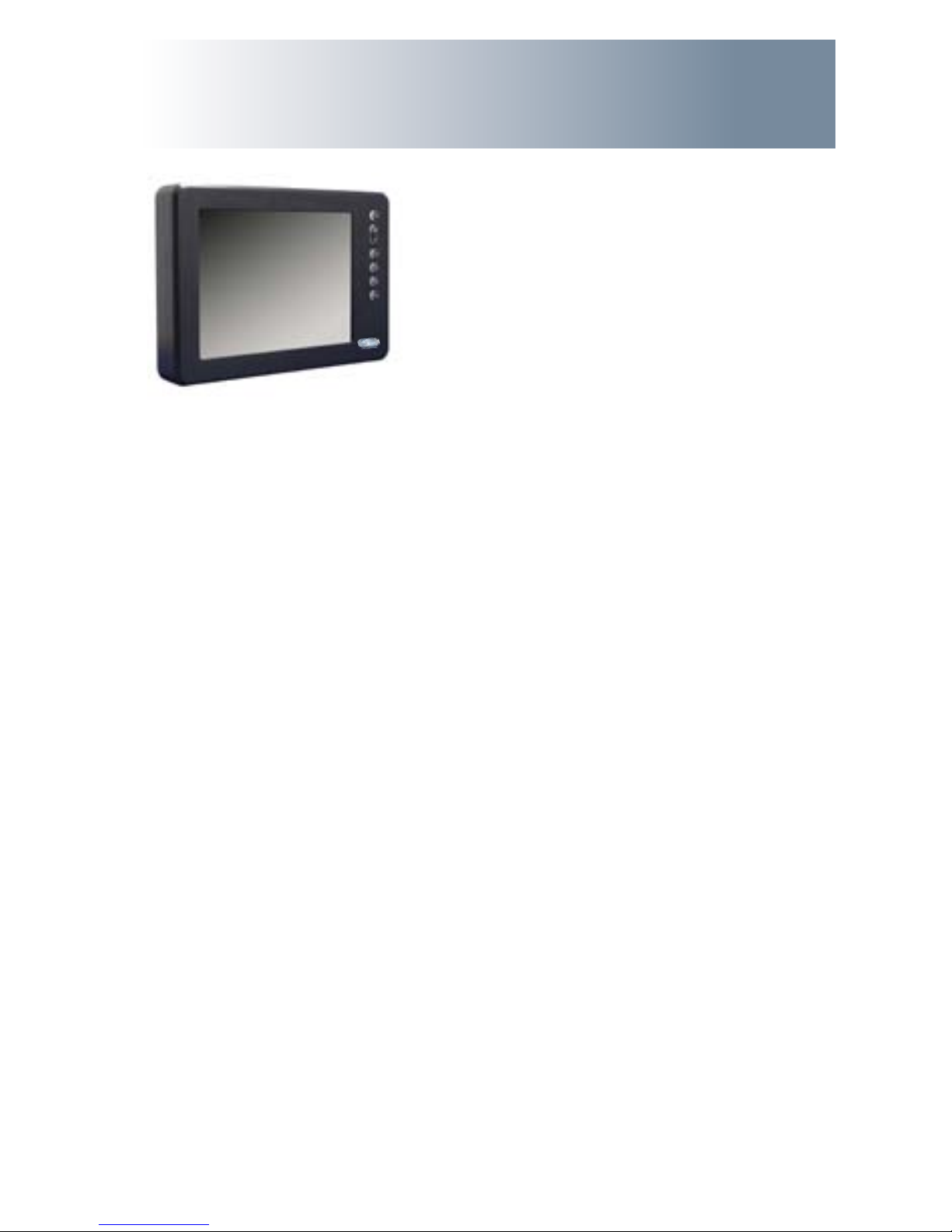
With this purchase of this All-Weather Professional Series LCD Monitor, the MPC-AWM3V
Series, we welcome you to Marine PC’s family of ruggedized marine Monitor and Com-
puter products.
You will soon become familiar with the quality dierence in this LED backlit bright
sunlight-readable (1 to 1,000 nits) Monitor, specically designed for marine applica-
tions. Marine PC has incorporated the latest optical engineering to achieve optimal
viewability in all lighting conditions.
The MPC-AWM3V handles a wide-range of severe environments, making it the rst
selection of many dierent users for their marine applications. Designed to be rugged,
this 800 x 600 SVGA (or optional 1028 x 768 XGA) Flat Panel Display is
engineered to thrive outdoors or indoors in any weather or lighting condition.
Housed in a milled billet aluminum case, the slim-prole MPC-AWM3V is light weight
and waterproof, with fully sealed (IP67) connectors. Engineered to have low-power
consumption, the MPC-AWM3V has three video inputs: Composite BNC coax, and a
source select button lets you quickly move between video inputs. There is also one
output to repeat the chosen input on a secondary display. All of our Professional Series
monitors oer extended operational temperature range and wide tolerance DC power
input.
Our Marine PC Technical Support Team is prepared to assist you, just contact us at:
suppor[email protected].
Welcome
5

UM-MPC-AWM3V(A) 10/2011
SAFETY
General Safety Instructions
• BeforeoperatingtheMPC-AWM3VMonitor,readthisUserManualthoroughly
• RetainthisUserManualforfutureuse
• Forexpeditiousinstallation,followtheseUserManualinstructionsinsequence
• AdheretoallCautionandWarningsonsystemandasstatedinthisUserManual
• AllUserManualinstructionsforinstallationandoperationmustbefollowed
precisely
• AdjustonlythosecontrolscoveredbytheUserManual’soperatinginstructions;improper
adjustment of other controls voids the unit’s warranty and may result
in unit damage, and
• Adheretolocalinstallationcodes.
General Unit Safety
• Alwaysdisconnecttheunitfromthepowersourcebeforecleaning
• Donotoperatetheunitwithadamagedcord
• Donotoperateiftheunithasbeendroppedordamaged.Theunitneedsinspection
by qualied Marine PC Service Personnel
• Positionthepowercordsoitwillnotbeincontactwithhotsurfaces
• Donotallowanythingtorestonthepowercord,and
• Donotplacethepowercordwheretherewillbefoottrac.
General Safety Precautions
• Powercordmustbeconnectedtoaproperlywiredandgroundedpowersource
• Anyequipmenttowhichtheunitwillbeattachedmustalsobeconnectedtoproperlywiredand
grounded power sources
• Donotconnectordisconnecttheunitduringanelectricalstorm
• Donotremovetheunitcovers–therearenouserserviceablepartsintheunit
• Donotdisassembleormodifytheunittoavoidthepossibilityofelectricalshock,
damage to electrical components or scratching the Display surface, and
• Disassemblyoftheunitvoidsthewarranty.
warning!
caution!
Warning! Shock Hazards
This icon is intended to tell you of a potential risk of electrical shock.
Caution! Instructional
This icon is intended to tell you of important operating and/or
maintenance instructions.
warning!
6

UM-MPC-AWM3V(A) 10/2011
Electrical
Connecting Cables
• DisconnectthepowerwhentheMonitorisbeinginstalled,and
• Uponinstallation,verifythepowerconnectorissecurelyseatedontheunit.
Power Source
This unit may be operated directly from a DC power source, or from AC with an external AC/DC
power converter..
• Usethesuppliedpowercable,and
• Alwaysconnecttoaproperlygroundedpowersource.
Fluids from LCD Display
• IftheMonitorshouldeverbecomeshattered,donottouchuidsfromanLCDDisplay
• Ifuidshouldgetonhandsorclothing,immediatelywipeowithliquidsoaporrubbingalcoholon
acleantowel;washwithwater;immediatelyconsultwithadoctor,and
• Ifuidgetsintheeyes,usheyesimmediatelywithwaterforaminimumof15minutes;consultwith
a doctor.
caution!
7
Protection on Servicing
Servicing - User
• Userproductservicingislimitedtocleaningtheunit
• Donotdisassembleormodifytheunittoavoidthepossibilityofanelectricalshock,damage
to electrical components or scratching the Display surface, and
• Disassemblyvoidsthewarranty.
Servicing - Marine PC
Marine PC Qualied Service Personnel may be required if the unit:
• Doesnotoperatenormallywheninstallationinstructionsarefollowed
• Doesnotoperatenormallywhenoperatinginstructionsarefollowed
• Hasbeendroppedordamaged,or
• Exhibitsadistinctchangeinperformance,indicatinganeedforservice.
Shipping
If the unit should need to be shipped to the Marine PC Service Center, the original packing
material should be used to insure safety of the unit in shipping. Repack the unit as it
would have originally been received from Marine PC.
This product has been engineered to meet or exceed international industry standards
addressing product design and enclosure protection against EMI/RFI when installed
with the factory provided cables.
EMI/RFI
caution!
UM-MPC-AWM3V(A) 10/2011
8
This MPC-AWM3V Monitor has been designed to provide optimum performance and service
without any required scheduled maintenance other than occasional cleaning.
Display Screen Cleaning
• Avinegar-basedcleanerispreferred:preventsstreaking,degradationofcoatings
• Anon-abrasiveglasscleanermaybeused,asinaprofessionalfoamglasscleaner
• Applythecleaningsolutiontoasoftcleancloth,dampeningslightly
• Keepafreshsideofthecleaningclothtowardsthescreensurfacetoavoid
scratching it with accumulated grit, and
• Tominimizetheriskofabrasiontothescreen,airdryingisrecommended.
Monitor Enclosure
• Cleantheunitenclosurewithasoftcleanclothlightlydampenedwithageneral
purpose mild detergent solution
• Torinse,wipedownwithcleanwater;drywithasoftcleancloth.
PRODUCT CARE AND MAINTENANCE
Product Care
• Donotuseabrasivecleanersorsolvent-based(ammable)cleanersontheFlatPanel,
enclosure or any other electrical device (cables, power cord, etc)
• DonotusepaperproductsastheymayscratchtheDisplayscreen,and
• DonotdirectlyapplycleaningsolutionstotheDisplayscreen.
Disconnect the Monitor from the power source before cleaning the Monitor,
optional Touch Screen or unit’s enclosure.
warning!
caution!
To avoid risk of electrical shock, do not disassemble the unit’s enclosure. Users
cannot service the Monitor. User maintenance is restricted to cleaning, as explained. Disas-
sembling the unit voids the warranty.
Long-term Storage
• Forlong-termstorage,itissuggestedtheunitbestoredinanormalindoorenvironmentand
the Display glass be protected from accidental damage
• Forpedestalmountunits,disconnectthecable(s)andloosenthearmadjustment
to a point where the ball can be removed from the arm, or
• ForFlushorPanelMountunits,covertheproductwithaprotectivecoveringthatwillnot
scratch or transfer any dyes to the Display screen.
Maintenance
Other Maintenance
Only Marine PC Qualied Service Personnel should perform all other maintenance except for
cleaning and the power cord replacement described below.
To avoid shock and re hazards, replaced the unit’s power cord if:
• Insulationbecomesdamaged,oralooseconnectionissuspected.
Power Cord
warning!
warning!
In marine or similar environments, an added benet of a vinegar-based
cleaner is its eectiveness in dissolving mineral and salt deposits.

UM-MPC-AWM3V(A) 10/2011 9
SYSTEM SETUP
System Requirements
The MPC-AWM3V accepts a standard NTSC or PAL composite video signal from any video source
such as a camera, VCR or DVD.
Shipping Box Contents
The MPC-AWM3V is shipped in a custom box with custom foam packaging. We
recommend you save the box and all packaging materials in case the unit would
need to be returned to the Marine PC Service Center. (Figure 1)
The shipping box contents are:
• MPC-AWM3Vunit
• MPC-AWM3VUserManual
• PowerCable
• MountingSystemandHardware
Figure 1
UM-MPC-AWM3V(A) 10/2011
10
INSTALLATION
The MPC-AWM3V is designed to be mounted with a universal ball-and-socket mounting kit, in a
Flat Panel position or optional Flush Mount conguration.
Pedestal Mount
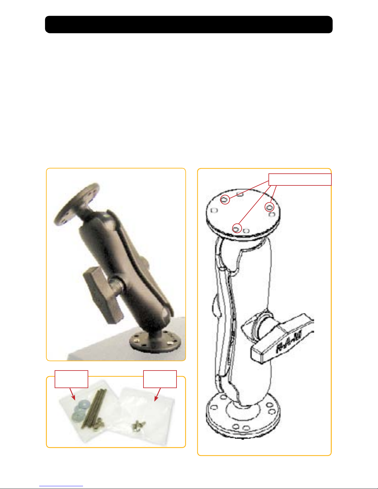
The MPC-AWM3V is shipped with a RAM® universal ball-and-socket system mounting kit (Figure
2). By installing the Monitor with this kit, the User can quickly adjust the
viewing angle to improve viewability in changing environments. This ball-and-socket
system has proven to be successful in supporting an extreme amount of weight in
highvibrationanddicult-mountapplications.SeeAppendixAforlinktodrawings.
Locate the ball-and-socket system in the shipping box. The kit consists of two RAM
balls on mounting plates and a RAM arm, with an adjustable T-knob and a packet of
three (3) M4 x 10 counter-sunk stainless screws for mounting to the MPC-AWM3V.
(Figures 2 - 4)
Figure 2
Figure 3 Figure 4
Mounting Holes
Panel
Mount Only
Ball and
Socket Mount
Only

UM-MPC-AWM3V(A) 10/2011 11
There are three mounting holes in the back of the Monitor for the ball mounting plate.
Take care not to strip the screw holes or over tighten. (Figure 4)
• Notethelocationofthethreemountingholesonaballmountingplate(Figure4)
• Withthree(3)M4x10counter-sunkstainlessscrewsattachthismountingplatetotheback
of the MPC-AWM3V.
• MountthesecondballmountingplatewheretheMonitorwillbeinstalled
• InserteachballintotheRAMarm
• LightlytightenthearmaroundtheballsusingtheT-knobonthearm(Figure2,4)
• AdjusttheMonitortotheviewingpreference,and
• TightentheT-knobtoholdtheMonitorinposition.
Itisrecommendedtheremainingballbemountedonaatsurface.Becauseofthe
various surface substrates the Monitor will be mounted on, the installer will provide
the screws to mount the other ball.
Panel Mount
ThePanelMountinstallationshouldbespeciedatthetimeoforder;theball-and-
socket mount system will not be included in the shipping box.
The mounting hardware packet is included with the unit accessories in the shipping
box. This packet includes four (4) threaded screws (approximately 7.6 cm [3”] long),
four(4)Nylocknutsandfour(4)atwashers.Forinstallation,therearefourtapped
mounting holes on the four corners of the unit’s rear panel.
It is recommended the installer refer to the mount drawings on the User CD or on
Marine PC’s web site, (www.marinepc.com/support), for the exact measurements of the unit’s
rear panel pod. These drawings should be helpful when the installer cuts the
required opening for the Panel Mount installation.
Take care not to strip the
screw holes or over tighten
as the enclosure is aluminum.
Flush Mount with Optional Bezel
WiththeoptionalFlushMountBezel,theMPC-AWM3VLCDDisplaymaybemountedushwith
themountingsurface;theball-and-socketmountsystemwillnotbeincludedintheshipping
box. The installer will need to supply screws for this type of installation.
The mount diagram of the Flush Mount Bezel is on the User CD and on Marine PC’s web site,
(www.marinepc/support). When the placement site has been decided, it is recommended the
installer use these measurements when cutting the opening for
the Monitor’s installation.
Note the locations of the milled holes in the Flush Mount Bezel. Drill corresponding holes into
the substrate where the Monitor will be mounted.
caution!
Take care not to strip the
screw holes or over tighten
as the enclosure is aluminum.
caution!
UM-MPC-AWM3V(A) 10/2011
12
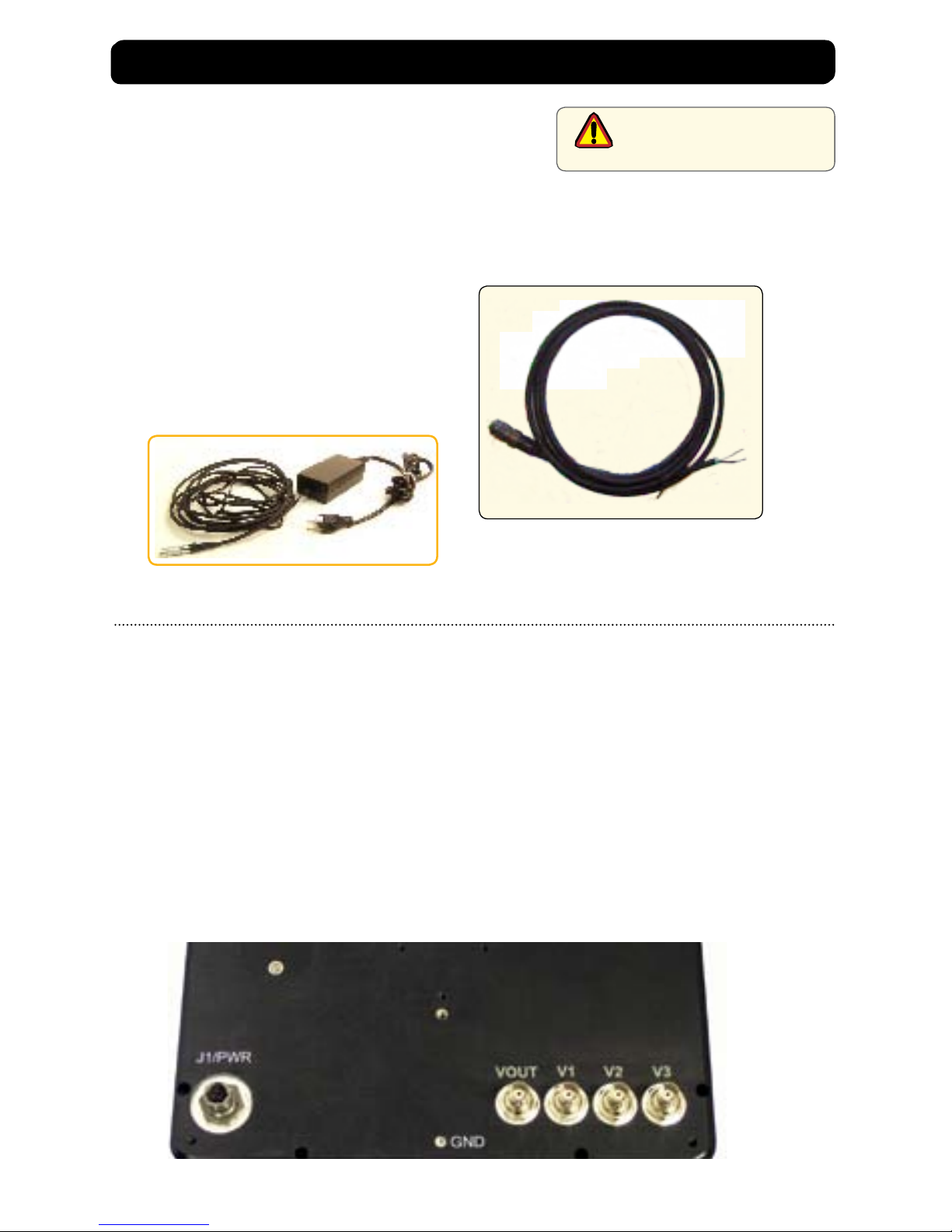
CABLE CONNECTIONS
Cables
• TheMPC-AWM3Vispackagedwithonecable:
DC Power, #1 in Figure5
Standard length cable is 3m. (10ft.)
Custom lengths can be ordered, or customer made
cables can be made using MIL-C connector (Amphenol
part no. PT06E833SSR )
• TheBNCcablesareprovidedbytheinstaller,and
• TheACPowerAdapterisoptional.(Figure6)
Connectors are located on the bottom of the unit housing, from left to right:
Power and 4-BNC.
Connectors are physically unique to insure the installer makes the proper connections.
Composite BNC Connector
The MPC-AWM3V accepts a standard NTSC or PAL composite video signal from any video source
such as a camera, VCR or DVD. This signal is carried to the Monitor via a coaxial video terminated
with a BNC connector.
• Theend-usersuppliestheBNCcoaxialvideocable(s)
• TheBNCreceptacleontheMonitorissealed
• Plugtogether,addinga¼twisttolockthetwopieces
• V-OutRepeatsthePrimaryDisplaytoSecondaryDisplays
caution!
Use care when inserting or
removing connectors.
Figure 5
Figure 6
Connectors

UM-MPC-AWM3V(A) 10/2011 13
DC Power Connector
• TheIP67sealedDCPowerCable,3m(10ft),isintheaccessorybox
• Pluginthequick-connect3-pinconnectorbylininguptheorientationpins,pushinandtwist
CW until it snaps in place.
• Todisconnect,twisttheoutsideringCCWandpullontheconnectorawayfromtheunituntil
the cable is free
• Therearetwoyingleads:negative:black(-)andpositive:white,labeledwith(+)
• ConnecttheyingleadstothecorrespondingpolarityontheDCvoltagesource
Optional AC Power Connector
• TheoptionalACPowerAdapterCableSetconsistsofa3m(10ft)cable,thepoweradapter
and a 1.8 m (6 ft) cable
• Thecableacceptsvoltagefrom110to250VACandfrequencyfrom47to63Hz
• TheACpowerplugisstandardfor120VAC/60Hz,commoninNorthAmerica,and
• Followprocedureabovetoforconnectiontotheunit.
caution!
Conrm the DC
connections are made to the
correct polarity.
caution!
When connecting or discon-
necting, never pull on the ca-
ble, only hold the connector..

UM-MPC-AWM3V(A) 10/2011
14
OPERATOR CONTROLS
On the right hand side of the Monitor
bezel are six Operator Control buttons.
Up/Right Arrow
Down/Left Arrow
Power On/O (I/O)
Button
Large sun
OSD Select Button
Adjust the brightness of the Display to the lowest possible setting for
a given set of conditions and display characteristics. Doing so will
provide the best viewing of the image, extend the life of the
backlight and reduce the internal heat of the Display.
Brightness
Control
Small sun
Select Button
The Select Button is the access point to the On-Screen Display (OSD) Source Screen Function
Menu and used for making selections from the OSD Menus. (See On-Screen Display.)
Up/Right Arrow Button
The Right Arrow Button is an adjustment tool in the On-Screen Display (OSD) Source Screen Con-
trols Menu. (See OSD Screen Control Menu Categories.)
Down/Left Arrow Button
The Down/Left Arrow Button is an adjustment tool in the On-Screen Display (OSD) Source Screen
Controls Menu. (See OSD Screen Controls Menu Categories.)
Source Select Button
The Source Select Button is used to select an Input Source when more than one Input is available.
Pushing this button will advance from the rst connected source to the next and then return to
the rst source in a circular fashion.
Brightness Buttons
These buttons control the brightness of the LCD Panel Display.
• Thelargesunbutton,whenrepeatedlypressedorhelddown,willcausethe
Display’s backlight brightness to increase.
• Thesmallsunbutton,whenrepeatedlypressedorhelddowncanbesteppeddowninincre-
ments to the lowest setting, which is backlight O, but the electronics are still on and synced
with the input signals. One step from the last is the lowest setting, and is suitable in very
subdued light, as in night time operations.
Optional Feature: Monitor defaults to an AUTO-
ON state when power is applied. This feature must be
ordered when the Monitor order is placed. It is not
available after the unit is built.
Power Button
Note: Monitor defaults to an AUTO-OFF state
when power is applied.
• ThePowerOn/Obuttonismarkedwith
the I/O (Input/Output) symbol
• Momentarilypressingthisbuttonwill
turn ON or turn OFF the unit.
• BlueLEDslocatedunderthebuttonsglow
when the unit is powered on.
Source Select Button

UM-MPC-AWM3V(A) 10/2011 15
ONSCREEN DISPLAY
The On-Screen Display (OSD) user interface is the path to make all video display signal source
adjustments. The Source Screen Controls Menu provides access to ne-tuning the Display.
OSD Source Screen Controls Menu Activation
To activate the OSD Source Screen Controls Menu in the active video source, press
and release the SELECT button.
Note: OSD Source Screen Controls Menu will close after 15 seconds of inactivity.
OSD Source Screen Controls Menu
The Controls Menu is comprised of seven source screen control categories with
adjustable settings.
Display Category Adjustments
• PresstheSelectbuttontoaccesstheControlsMenu
• IntheControlsMenu,tochooseaDisplayCategory,usetheRIGHTorLEFTArrow
button to move UP or DOWN the Controls Menu
• TheControlsMenuitemchangescolor,fromblacktored,whenitisactive
• WhenaControlsMenuitemisinred,presstheSelectbuttontoopen
• TheadjustmentcontrolsaretheRIGHTandLEFTArrowbuttons,whichincreaseor
decrease the value of the menu item’s parameter as noted in the indicator screen
• Createthenewparametervalue
• PresstheSELECTbuttontosavethenewvalue;thisreturnstheUsertotheControlsMenu
• MovetheRIGHTorLEFTArrowbuttontomovetoanotherControlsMenuitem,or
• MovetheRIGHTorLEFTArrowbuttontoExit.
• New settings will be stored in memory upon pressing the SELECT button to exit the OSD
Source Screen Controls Menu item.
• If SELECT is not pressed, or inactivity is detected within the 15 second
factory default OSD menu duration, any screen function adjustments made
will be saved.
It is recommended to adjust the LED back light brightness
to maximum before ne-tuning the OSD Source Screen
Controls Menu Parameter: Brightness.
OSD Source Screen Controls Menu Categories
caution!

UM-MPC-AWM3V(A) 10/201116
Controls Menu Parameters
Video Horizontal
Video Horizontal adjusts the picture screen, left to right.
• Openthe“VideoHorizontal”function,and
• PresstheRIGHTorLEFTArrowbuttontoadjustthedisplay’shorizontalposition.
Video Vertical
Video Vertical adjusts the picture screen, top to bottom.
• Openthe“VideoVertical”function,and
• PresstheRIGHTorLEFTArrowbuttontoadjustthedisplay’sverticalposition.
Video Brightness
Before adjusting the Video Brightness parameters, set the LCD panel back light
brightnessusingthelargesunbutton;settoitsbrightestintheambientlight
source.
• Openthe“VideoBrightness”function,and
• PresstheRIGHTorLEFTArrowbuttontosettheDisplay’sdesiredbrightness.
Video Blacklevel
Video Blacklevel adjustment intensies or decreases the saturation of black.
• Openthe“VideoBlacklevel”function,and
• PresstheRIGHTorLEFTArrowbuttontosettheDisplay’sdesiredblacklevel.
Video Contrast
Video Contrast is the dierence in brightness between the light and dark areas of the
pixels of the picture.
• Openthe“VideoContrast”function,and
• PresstheRIGHTorLEFTArrowbuttontosettheDisplay’sdesiredcontrast.
Video Hue
Video Hue is the pinks, blues and greens of the Display.
• Openthe“VideoHue”function
• PresstheRIGHTorLEFTArrowbuttontosettheDisplay’sdesiredtint,and
• RangesontheDisplaybarare:low–pinks;mid-range–greensandupper–blues.
Video Color
Video Color adds or subtracts color values from the picture.
• PresstheLEFTArrowbuttontoremovecolorandgotoblackandwhite,and
• PresstheRIGHTArrowbuttontoaddcolor.
Recall
The Recall feature resets the Controls Menu items to factory default.
• Select“Recall“controltoresetallthecontrolstofactorydefault,and
• PresstheSelectbuttontosavechanges.
Exit
• PresstheRIGHTorLEFTArrowbuttontogettoExit,and
• PressSelecttoExit.

UM-MPC-AWM3V(A) 10/2011 17
Mechanical Drawings
Mount diagrams of the MPC-AWM3V and its dimensions may assist you in installation of the
Monitor. You may nd them on our website at:
http://www.marinepc.com Look in the Support Tab for Drawings
Mount diagrams of the optional Flush Mount Bezel and its dimensions may assist you in installa-
tion of the Monitor. You may nd them on our website at:
http://www.marinepc.com Look in the Support Tab for Drawings
APPENDIX A
APPENDIX B
Symptom: No light behind button LEDs
Possible Problem Solution
No power, loose power connection Conrm the Monitor is properly connected to a DC or
AC power source.
Verify the power source is live or try another battery
or AC power outlet.
Verify the Monitor is powered on.
Reverse Polarity Check polarity of the power connection.
Symptom: Light behind button LEDs, no display, or “No Signal”error message
and/or no image on the display
Possible Problem Solution
Power on, no video signal Verify a video signal is coming out of the signal source
(i.e., plug into a known good display source).
Verify the incoming signal source selected matches
the Monitor signal source (Composite, S-Video).
Check the Brightness front panel setting on the Moni-
tor. This may be set too low.
Check the Brightness and Contrast controls in the
OSD. These may be set too low.
Display

UM-MPC-AWM3V(A) 10/2011
18
Symptom: Display has rolling“bars” across the screen or vertical shaded bars on
Possible Problem Solution
Defective video cable On a known good display source, conrm the video
cable is not defective.
Interference from adjacent equipment For proper grounding and shielding, verify use of a
proper video cable.
KeepthecableawayfromsourcesofEMIsuchas
electric motors, or unshielded RF
sources such as radar and microwave.
Horizontal size is not adjusted In the OSD, adjust the Video Horizontal controls.
Symptom: Picture quality, image stability is distorted.
Possible Problem Solution
Proper cable grounding and shielding Verify the use of a proper video cable with suitable
groundingandshielding.Keepthevideocableaway
from sources of EMI and RFI.
Improper video display settings Check signal source for proper signal.
Check for proper display properties selection of the
display pixel setting.
Display unit is farther than 3 m (10 ft) from signal
source
Single cable lengths in excess of the standard 3 m
(10 ft) cable should be of high quality shielded ca-
ble. Contact DSE for information on custom cables.
Multiple Monitors are driven from the same signal
source.
Splitting the video signal divides the strength of
the signal. A video signal booster (line driver) is
recommended if installation requires more than one
Monitor driven from a single video source.
Monitor has incorrect or bad sync signals. Check for proper video cable installation, or replace
suspected faulty cable.
Symptom: Display image is not properly sized
Possible Problem Solution
OSD adjustments need to be made Adjust the Video Vertical and Horizontal
controls through the OSD.
APPENDIX B CONT’D

UM-MPC-AWM3V(A) 10/2011 19
APPENDIX C
Technical Specications
8.4” 10.4” 12.1” 15”
Display TFTAM,SVGA,LCD,256KColors.800x
600 pixels
üü
1024 x 768 XGA
16.2 Mil Colors
Standard
Sunlight
Readable 1,000 nits Nominal, AR/AG ü ü ü
Dimming Ratio 1,000:1 ü ü ü
Video Input NTSC/PAL(B,D,G,I,K) ü ü ü
Connectors Video: Inputs-BNC-F, Output-BNC-M
Mating Conn: Amphenol PT06E833SSR
ü ü ü
Housing Milled Aluminum, Black Anodized,
UV Clear Coat ü ü ü
Mounting Panel Mount (Studs) or RAM Mount
Optional Flush Mount with Bezel
ü ü ü
Power
Consumption 6 Watts Min - 14 Max 15 Max 17 Max 35 Max
Wide Range
DC Input
10-30 VDC
(12, 24, 28 VDC nominal)
ü ü ü
Environmental Specications
8.4” 10.4” 12.1” 15”
Operating Temp -40°C to70°C (-40°F to 158°F) ü ü ü
Storage Temp -40°C to 75°C (-40°F to 167°F) ü ü ü
Shock 50 G ü ü ü
Vibration 5.8 G (5-500 Hz) ü ü ü
IP Rating IP67 (NEMA 6P Submersible) ü ü ü
Humidity 0-100% ü ü ü
EMI Designed to meet FCC B, CE ü ü ü
Altitude 45,000 ft. ü ü ü

UM-MPC-AWM3V(A) 10/2011
Warranty Terms and Conditions
MarinePC offers it’s products and services
for sale under the following terms and con-
ditions. Any and all orders will be accepted
only at the sole discretion of MarinePC and
under these terms and conditions. Any
modication to these terms and conditions
can only be made by MarinePC in writing.
Agreement to any modications must be
made by all participants of the sale prior to
the acceptance of any order.
Prices: All published prices are in effect
from the date noted on the price sheet.
Prices are subject to change without no-
tice. Written quotations may be requested.
Written quotations are valid for 30 days. All
prices are quoted in U.S. dollars. Any and all
taxes, tariffs, currency translations, duties,
insurance, freight charges and any other
handling charges are the responsibility of
the purchaser, and must be prepaid and/
or charged.
Acceptance: All orders will be accepted at
the sole discretion of MarinePC. Any order
can be rejected for any reason at any time
without liability.
Payment: All purchasers must prepay the
order, accept COD shipment or arrange for
other acceptable methods of guaranteed
payment (credit card, cash prepayment,
etc.) before any order will be shipped. VISA,
MasterCard, DiscoverCard and American
Express are welcomed and encouraged.
Shipments: All shipments are FOB Scott-
sdale, Arizona. Purchaser is encouraged
to provide MarinePC with shipping autho-
rization on their freight account. Unless
otherwise specied, MarinePC will select
the best way for shipment, using common
carrier, FedEx Ground or UPS Ground.
Shipments that are not FOB consignee or
third party will incur a 20% handling charge
and be added to the invoice. Delivery is not
guaranteed. All risk of loss is assumed by
the purchaser upon delivery by MarinePC
to the carrier. Special terms may apply for
international shipments. Unless otherwise
specied by the purchaser and accepted by
MarinePC at the time of purchase, MarinePC
reserves the right to partial ship any order.
Cancellations: Once an order is placed by
the purchaser and accepted by MarinePC,
cancellation charges will apply to any and
all unshipped items. Partial credit may be
extended if products are returned unused
in original packaging within 30 days of
shipment. No credit will be issued on any
returns or cancellations after 30 days from
date of shipment.
Returns: Once a product has been shipped,
no returns will be accepted unless an RMA
number has been issued by MarinePC prior
to it’s return. The RMA number must be
prominently displayed on the outside of
the returned packing materials. MarinePC
cannot be responsible for damage from ship-
ping. All authorized returns must be shipped
prepaid directly back to MarinePC in the
original packaging. Returnee is responsible
for all shipping and handling costs to and
from the closest MarinePC authorized repair
location. For authorized in-warranty service
only, MarinePC will pay for the return of the
unit via normal domestic ground service.
Expedited return service or shipment outside
of U.S. must be prepaid by receiving party.
Standard Limited Warranty: MarinePC war-
rants its products to be free from defects
in materials for a period of Two (2) Years
from the date of the original shipment from
the factory. MarinePC agrees to repair the
product without labor cost to the purchaser,
for a period of One (1) Year from the original
ship date. No other warranty is expressed
or implied. Specically excluded is normal
wear and tear, abuse or misuse of the prod-
ucts. MarinePC does not make any claims
or warrant the products with respect to the
purchaser’s use or application of the prod-
ucts. Products returned but found not to be
within the terms of this warranty are subject
to a service fee to be paid prior to the return
of the product to the purchaser.
Liability: Any claim which may be made
against MarinePC with regard to this con-
tract for sale must occur within One (1)
year from date of original shipment from
the factory. IN NO EVENT SHALL MarinePC
BE LIABLE FOR LOSS OF PROFITS, LOSS
OF USE, LEGAL OR PROFESSIONAL FEES,
CONSEQUENTIAL OR INCIDENTAL DAMAGE
OR FOR SPECIFIC PERFORMANCE OF THE
PRODUCTS, THEIR MERCHANTABILITY OR
FITNESS FOR ANY PARTICULAR PURPOSE.
Table of contents
Other Marine PC Monitor manuals


