Markem Imaje DigiConvert MC004-2014 P1082 User manual

Copying this document, or disclosing it to third parties is not allowed without our approval. This document must not be used in any abusive way by the receiver or third
parties. Feldbaum + Vogt GmbH
DigiConvert Operating Instructions
1 of 79
Markem Imaje CSAT GmbH
DigiConvert
Mach. no. MC004-2014
P1082
Operating Instructions
© Feldbaum + Vogt GmbH
Dieselstr. 12
32791 Lage
Germany
Version modifications:
Version
Date
Name
Comments
1.0
Wiens

DigiConvert Operating Instructions
Copying this document, or disclosing it to third parties is not allowed without our approval. This document must not be used in any abusive way by the receiver or third
parties. Feldbaum + Vogt GmbH
DigiConvert Operating Instructions 2 of 79
Contents
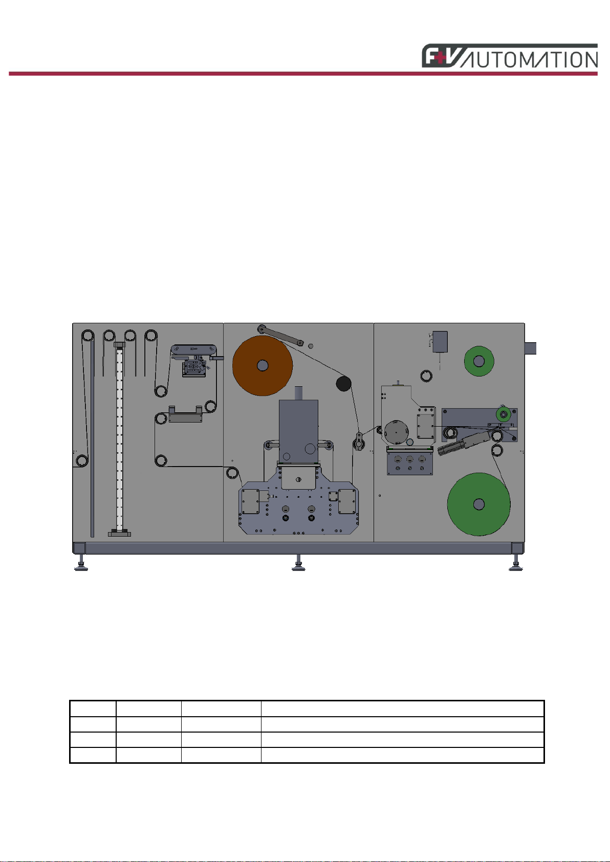
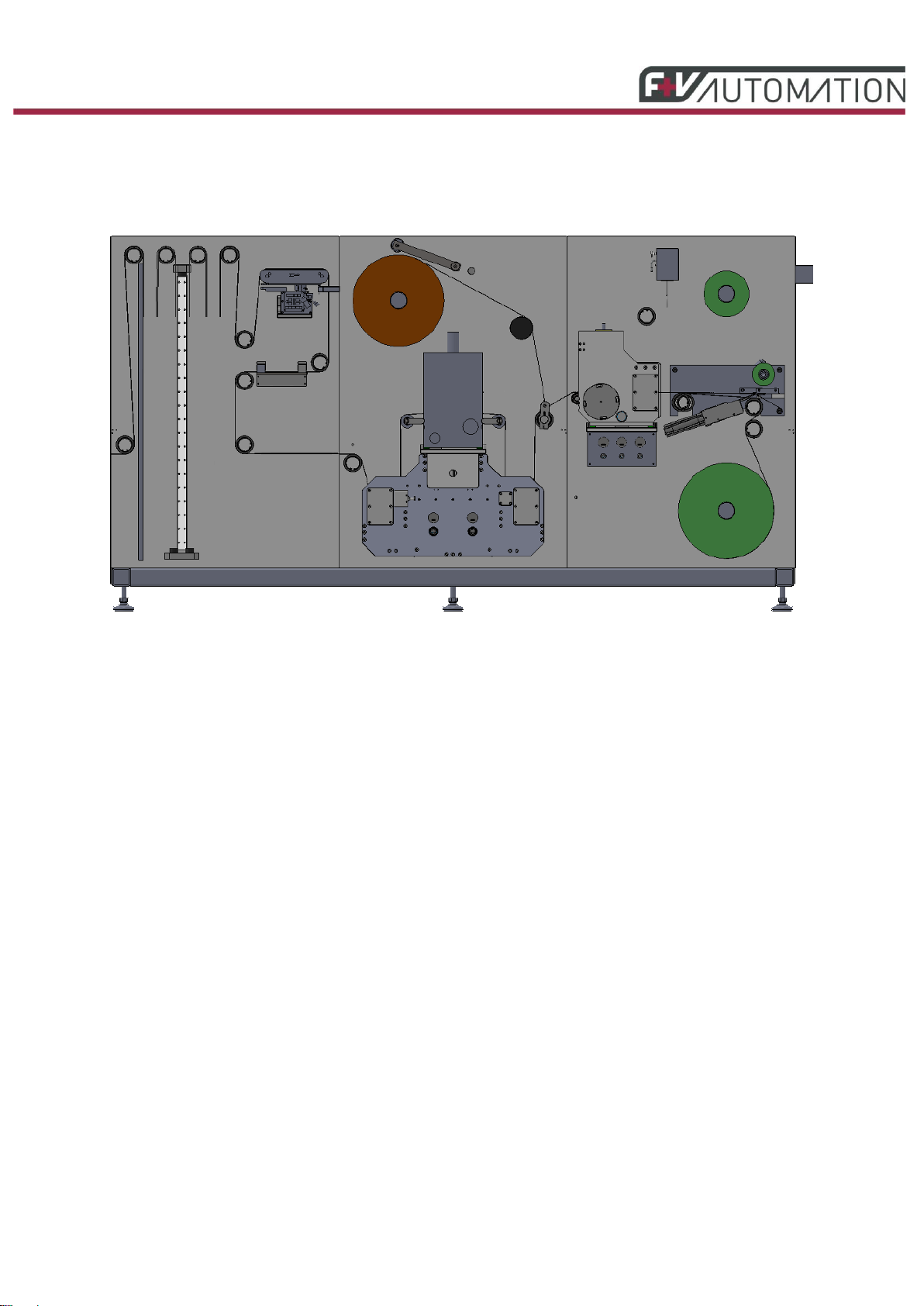
1. MACHINE........................................................................................................................................ 4
2. FIELD OF APPLICATION............................................................................................................... 4
3. MACHINE SPECIFICATION........................................................................................................... 4
4. WARNINGS AND SAFETY INSTRUCTIONS ................................................................................ 5
4.1. GENERAL INFORMATION ................................................................................... 5
4.2. CONTACT FOR SALES,MAINTENANCE AND HELP ............................................... 5
4.3. SKILLED PERSONNEL....................................................................................... 6
4.4. UTILISATION.................................................................................................... 6
4.5. WARNING OF RESIDUAL RISKS .......................................................................... 6
4.6. MAINTENANCE INSTRUCTIONS........................................................................... 7
5. INSTALLATION AND STARTUP ................................................................................................... 7
5.1. INSTALLATION ................................................................................................. 7
5.2. STARTUP ........................................................................................................ 7
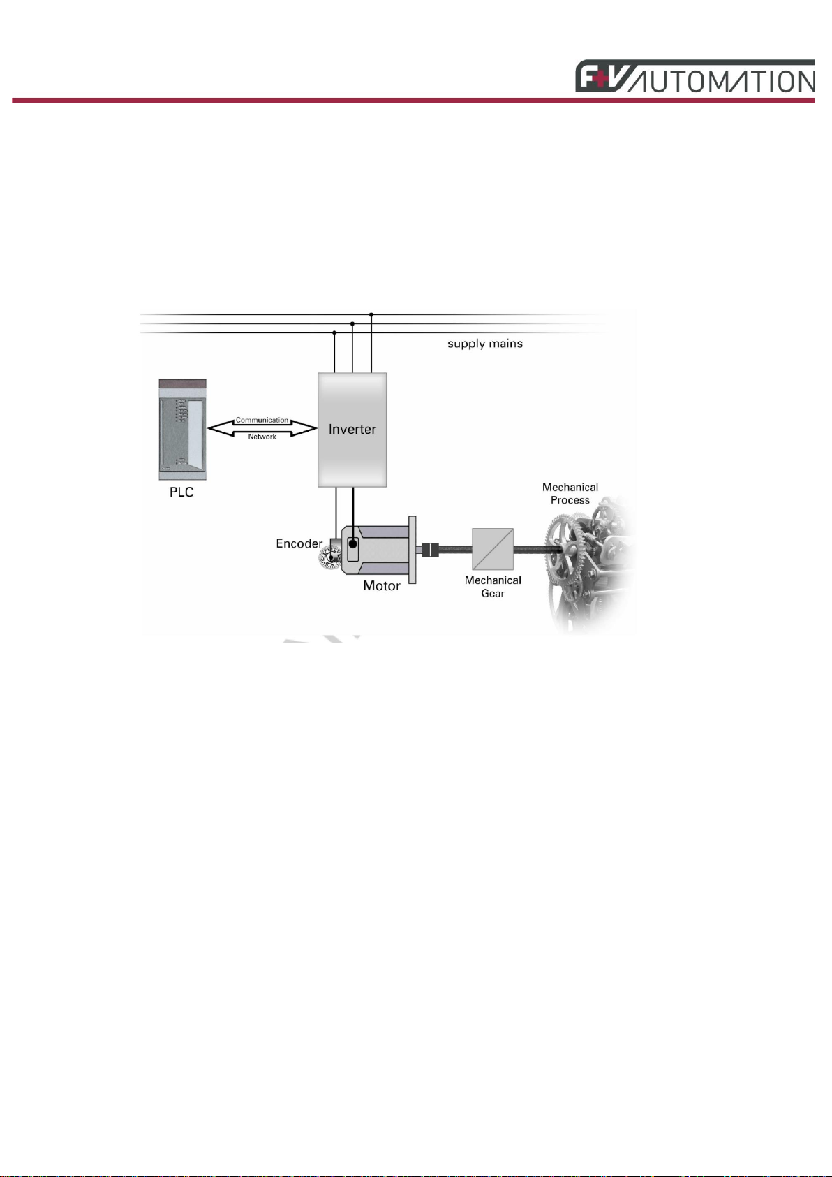
6. INTRODUCTION............................................................................................................................. 8
6.1. FUNDAMENTALS OF DRIVE ENGINEERING........................................................... 8
6.2. OPERATOR TERMINAL...................................................................................... 9
6.2.1. MAIN OPERATOR TERMINAL ........................................................................ 9
6.3. WARNING LIGHT SYSTEM FOR THE ENTIRE MACHINE........................................ 10
7. SAFETY FUNCTIONS .................................................................................................................. 11
7.1. SAFETY HOODS............................................................................................. 11
7.2. EMERGENCY STOP FUNCTION......................................................................... 12
7.2.1. TRIGGERING EMERGENCY STOP............................................................... 12
7.2.2. ACKNOWLEDGING EMERGENCY STOP ....................................................... 12
8. OPERATING THE MACHINE....................................................................................................... 13
8.1. SWITCHING ON THE SYSTEM ........................................................................... 13
8.2. OPERATIONAL CONCEPT................................................................................ 13
8.2.1. GENERAL OPERATION.............................................................................. 13
8.2.2. ICONS AND COLOURS............................................................................... 14
8.2.3. LATERAL EDGE CONTROL ........................................................................ 14
8.3. MACHINE CONTROL BUTTONS,MACHINE STATUS............................................ 15
8.4. SWITCHING OFF THE SYSTEM.......................................................................... 17
9. MENU STRUCTURE..................................................................................................................... 18
9.1. WELCOME SCREEN........................................................................................ 18
9.2. MACHINE OVERVIEW...................................................................................... 19
9.3. CHANGE OF OPERATOR.................................................................................. 28
9.4. DRIVE VALUES TREND DIAGRAM ...................................................................... 29
9.5. MACHINE SETTINGS AND JOB MEMORY........................................................... 30
9.6. QUICK OPERATION ........................................................................................ 37
9.7. REGISTER REGULATOR TREND DIAGRAM ........................................................ 39
9.8. ALARMS –HISTORICAL VIEW.......................................................................... 41

DigiConvert Operating Instructions
Copying this document, or disclosing it to third parties is not allowed without our approval. This document must not be used in any abusive way by the receiver or third
parties. Feldbaum + Vogt GmbH
DigiConvert Operating Instructions 3 of 79
9.8.1. ALARMS FROM INDIVIDUAL AXES............................................................... 42
9.9. SYSTEM DIAGNOSIS....................................................................................... 43
9.10. GENERAL MACHINE INFORMATION ............................................................... 44
9.11. HELP......................................................................................................... 45
10. ERROR MESSAGES AND WARNINGS .................................................................................. 46
11. OPERATING THE ASSEMBLIES............................................................................................. 47
11.1. REELER..................................................................................................... 47
11.1.1. REELER MAIN MENU STANDARD REELER............................................... 47
11.1.2. REELER SUBMENU REELER................................................................... 50
11.1.3. CONFIGURATION MENU ........................................................................ 54
11.2. LONGITUDINAL CUTTER,TRANSLATIVE PULL AND MATRIX REMOVAL ............. 56
11.2.1. MAIN MENU ......................................................................................... 56
11.2.2. MENU SMO LONGITUDINAL CUTTER....................................................... 58
11.3. PUNCHING STATION .................................................................................... 61
11.3.1. GENERAL INFORMATION ABOUT THE PUNCHING STATION ........................ 61
11.3.2. MAIN MENU ......................................................................................... 62
11.3.3. PUNCH SUBMENU................................................................................. 65
11.4. TRANSLATIVE COMPENSATION..................................................................... 68
11.4.1. MAIN MENU ......................................................................................... 68
11.5. WEB STORAGE .......................................................................................... 70
11.5.1. MAIN MENU ......................................................................................... 70
11.6. LABEL DELIVERY........................................................................................ 72
11.6.1. MAIN MENU......................................................................................... 72
11.7. COUNTING FUNCTIONS MAIN MENU ............................................................. 74
12. MAINTENANCE INSTRUCTIONS............................................................................................ 77
13. FIGURES................................................................................................................................... 79

DigiConvert Operating Instructions
Copying this document, or disclosing it to third parties is not allowed without our approval. This document must not be used in any abusive way by the receiver or third
parties. Feldbaum + Vogt GmbH
DigiConvert Operating Instructions 4 of 79
1. Machine
Fig.: 1 Machine overview
2. Field of Application
The main focus of the manufactured products is on punching, cutting and winding up material webs.
3. Machine Specification
Type
DigiConvert
Machine speed
1 m/min ... max. 50 m/min
Machine speed (translative)
1 m/min ... max. 40 m/min
Safe machine speed
1 m/min ... max. 5 m/min
Web tension
max. 250 N m (± 5% with acceleration)
Web width
22 ... 230mm
Cylinder length
mm
Gearing
1/8 in c.p.
Reeler core diameter of tensioning shaft
3 in / 76.20 mm
Reeler, max. diameter
400 mm
Matrix reeler, max. diameter
600 mm
Compressed-air supply building side
6 bars
Sound-pressure level
< 75 dB(A)

DigiConvert Operating Instructions
Copying this document, or disclosing it to third parties is not allowed without our approval. This document must not be used in any abusive way by the receiver or third
parties. Feldbaum + Vogt GmbH
DigiConvert Operating Instructions 5 of 79
4. Warnings and Safety Instructions
4.1. General information
These operating instructions describe all functions and procedures that are necessary for a safe and
proper operation of the machine.
To ensure a precise and faultless utilisation of the machine, please make yourself familiar with the
operating instructions before you start operation.
Only instructed skilled personnel are allowed to operate and maintain the machine.
Ensure that all persons who work on the machine have access to these operating instructions, and
that the specifications and instructions are observed and followed.
Please ensure that these operating instructions are always complete, without any missing pages, and
are in a good and readable state.
Operate the machine only if you are sure that it is in a safe and faultless state.
Comment:
Under certain conditions, incorrect parameter settings can have a negative effect on the tool station
and the entire machine. This is particularly important for the configuration parameters, which should
only be set and modified by skilled personnel who have been authorised for this work by Feldbaum +
Vogt GmbH, or by properly trained persons.
These critical parameters are password-protected. The corresponding chapters in these operating
instructions inform whether or not a parameter can be modified by the operator.
4.2. Contact for Sales, Maintenance and Help
Feldbaum + Vogt GmbH
Dieselstr. 12
32791 Lage
Phone: +49(0)5232 703709-0
Fax: +49(0)5232 703709-9

DigiConvert Operating Instructions
Copying this document, or disclosing it to third parties is not allowed without our approval. This document must not be used in any abusive way by the receiver or third
parties. Feldbaum + Vogt GmbH
DigiConvert Operating Instructions 6 of 79
4.3. Skilled Personnel
The person who is responsible for the overall system is obliged to delegate and entrust the operation
to skilled personnel.
In accordance with this documentation, these are persons who:
•Are familiar with the general safety and accident-prevention regulations.
•Are authorised to operate the system and are, in accordance with their training and
experience, familiar with the operating instructions and the applicable directives and
regulations.
4.4. Utilisation
Operate the system only in accordance with the descriptions in the documentation. Any exceptions
must explicitly be approved by Feldbaum + Vogt GmbH.
The system described in the documentation was developed, manufactured, tested and documented in
accordance with the valid safety directives. Under normal conditions, there should therefore not be
any danger to health or risk of material damage.
Proper transport, correct installation, and cautious operation and maintenance are prerequisites for
normal and safe operation of the system.
The system is intended to be used and operated in a closed building.
Certain configuration parameters can not be accessed by the machine operator and may not be
modified. Such parameters are password-protected. They may only be modified by skilled personnel
who have been authorised by Feldbaum + Vogt GmbH.
4.5. Warning of residual risks
As soon as you open the doors of the control cabinet or remove devices that protect against
accidental contact, you have access to certain system components that can carry dangerous voltage.
Only skilled personnel are allowed to access the system.
Danger of crushing and cutting!
The system controls moving machine components (such as punching tools and cylinders). Ensure that
no limb can get into the danger zone of such a machine component. This could cause severe injuries.
Please observe and follow always the valid safety and accident-prevention regulations that are
applicable when you operate the machine.

DigiConvert Operating Instructions
Copying this document, or disclosing it to third parties is not allowed without our approval. This document must not be used in any abusive way by the receiver or third
parties. Feldbaum + Vogt GmbH
DigiConvert Operating Instructions 7 of 79
4.6. Maintenance Instructions
Working on the system
Only personnel who have been authorised by Feldbaum + Vogt GmbH, or personnel who have been
adequately trained and instructed are allowed to repair or modify the system.
Improper maintenance or unauthorised opening of the control cabinet and its components can cause
severe injuries and/or significant material damage.
Only appropriately trained personnel are allowed to carry out the general maintenance work in
accordance with this documentation.
Under normal working conditions, the system components do not require any measures or
modifications. Changing the settings of the knobs underneath the control unit and the servo amplifier
front panel is not permitted. Any manipulation of these components has a direct and negative effect on
the system and possibly on higher-order machine components. As a result, there can be unpredictable
and dangerous situations.
5. Installation and Startup
This chapter contains instructions for initialisation and startup of the machine. The subchapters refer to
the corresponding applicable electrical circuit diagrams and mechanical drawings.
5.1. Installation
The electrical and mechanical modules must be installed in accordance with the valid regulations. All
work must be carried out by skilled personnel.
(See Chapter 4.3 Skilled Personnel).
5.2. Startup
Only service engineers who have been approved by Feldbaum + Vogt GmbH are authorised to
parameterise and start up the machine in agreement with special customer agreements in the current
setting.

DigiConvert Operating Instructions
Copying this document, or disclosing it to third parties is not allowed without our approval. This document must not be used in any abusive way by the receiver or third
parties. Feldbaum + Vogt GmbH
DigiConvert Operating Instructions 8 of 79
6. Introduction
6.1. Fundamentals of Drive Engineering
The following figure shows the basic components of an
electrical drive system:
Fig.: 2 Components of the Electrical Drive System
The machine (mechanical process) is driven by an electric motor. If necessary, the mechanical
coupling uses a mechanical gearbox to adjust speed and torque. The electrical drive converts
electrical energy into mechanical
energy (torque, force). To control the motor movements, a power converter converts the electrical
energy as required. A position encoder informs of the current position of the drive and the position of
the machine. The power converter receives its commands from a controller CPU. In this CPU, the
application program is executed that implements the required
sequence of movements.

DigiConvert Operating Instructions
Copying this document, or disclosing it to third parties is not allowed without our approval. This document must not be used in any abusive way by the receiver or third
parties. Feldbaum + Vogt GmbH
DigiConvert Operating Instructions 9 of 79
6.2. Operator Terminal
The entire system is controlled via the main control panel, that consists of a touch screen monitor and
several buttons.
Fig.: 3 Main Operator Terminal
6.2.1. Main operator terminal
The base functions, such as STOP, PREP, START, JOG, are activated by the buttons with these
inscriptions on the screen.
The key switch with the states "0" and "1" is used to enable configuration mode (SERVICE mode). In
configuration mode, you can make power-unit-specific settings and settings for the entire machine.
Only trained personnel are allowed to make these settings.
With the exception of the above-mentioned base functions, the entire machine is controlled via the
touchscreen monitor. All system components are represented graphically with corresponding icons.
An alarm menu transfers real-time information about the fault status of each individual drive.
Production data (speeds, web tensions) is interrogated and displayed continuously.
Once the system has been switched on, the operator can calibrate the touch screen monitor to ensure
that the console software can allocate all button activities correctly. Recalibrating the monitor is not
usually necessary. The calibration data is continuously saved in the console memory.
Use the following procedure if recalibration is necessary (if buttons can be pressed,
but no longer aligned):
•Start the system
•Inside the remaining time that is shown by the moving bar, press at any point on the monitor to
get to the calibration page.
•This displays little targets at various points. Press these points at the highest precision
possible.
•Calibration is completed when the original screen reappears.
•Calibration was not successful if the first target reappears.
•In this case, repeat calibration.

DigiConvert Operating Instructions
Copying this document, or disclosing it to third parties is not allowed without our approval. This document must not be used in any abusive way by the receiver or third
parties. Feldbaum + Vogt GmbH
DigiConvert Operating Instructions 10 of 79
6.3. Warning Light System for the Entire Machine
Signal column at the operator terminal
Status red
The red status means:
➢Blinking: EMERGENCY STOP mode active, acknowledgement with the emergency stop reset
button necessary
oThe blue lamp of the emergency stop reset button shines continuously
➢Permanently red: The machine is in STOP mode
Status yellow
The yellow status means:
➢Blinking: PREP status has not yet been reached
➢Permanently yellow: The machine is in PREP mode
Status green
The green status means:
➢Blinking: Although the machine is in START mode, it has not yet reached the desired speed.
➢Permanently green: The machine is in START mode, the desired speed is reached.

DigiConvert Operating Instructions
Copying this document, or disclosing it to third parties is not allowed without our approval. This document must not be used in any abusive way by the receiver or third
parties. Feldbaum + Vogt GmbH
DigiConvert Operating Instructions 11 of 79
7. Safety Functions
7.1. Safety Hoods
There are sources of danger (crushing points, catching points, etc.) on the machine that are
dangerous for the operator. Using mechanical structures, most of these danger points have been
designed such that they are no longer dangerous for the operator. However, machine operation
requires some of these danger points to be accessible. These danger points are protected by safety
hoods that can be opened. A safety switch interrogates the state of the safety hood. If a safety hood is
opened, any danger points behind are safely switched off depending on the current machine state.
This means that drives are safely braked for the process, and switched torque-free. Pressure rolls
open.
This means: If you open a protective hood while the machine is running, the machine stops as quickly
as possible, and the related drive is safely switched off.
Starting the machine with open protective hood and selected drives is not possible.
Danger points include punch, longitudinal cutter, matrix removal, translative pull, and other pulling
stations.
The machine is equipped with six safety hoods. See Figure.
Hood
Top left
Hood
Top centre
Hood
Top right
Hood bottom
left
Hood bottom
centre
Hood bottom
right
If the protective hoods are opened, an emergency stop is triggered depending on the machine state.
Hood
State
top
bottom
left
centre
right
left
centre
right
STOP
-
-
-
-
-
-
PREP
-
-
-
Emergency
stop
Emergency
stop
-
RUN
Emergency
stop
Emergency
stop
Emergency
stop
Emergency
stop
Emergency
stop
Emergency
stop
JOG
-
-
-
Emergency
stop
Emergency
stop
-

DigiConvert Operating Instructions
Copying this document, or disclosing it to third parties is not allowed without our approval. This document must not be used in any abusive way by the receiver or third
parties. Feldbaum + Vogt GmbH
DigiConvert Operating Instructions 12 of 79
In addition, the machine is equipped with a safe jogging switch. Press and hold the jogging switch to
move the punch at a safe speed up to 5 m/min when the top centre safety hood is open. The entire
machine is moved at this speed when all the outer hoods are closed.
7.2. Emergency Stop Function
7.2.1. Triggering Emergency Stop
There are emergency stop switches on the main operator terminal and on the assembly terminals.
Pressing one of the buttons has the following effect:
1. The machine is stopped inside the shortest time possible.
2. The drives are set to the Safe Torque Off (STO) state. This means that no torque-generating
energy can act on a motor, which prevents an unwanted start.
The 24-V control voltage is retained. The servomotors do not produce any torque.
The supply voltage to motors without STO function is switched off.
3. The red lamps of the warning light system and on the main operator terminal blink. The blue
lamp in the reset emergency stop button shines permanently.
7.2.2. Acknowledging Emergency Stop
To terminate the emergency stop condition, first pull out all pressed emergency stop switches (safe
restart lock). Once this has been done, the blue lamp in the emergency stop reset button on the main
control panel starts blinking. Pressing the emergency stop reset button once is enough.
In addition, acknowledge any occurred alarm messages.
The machine then returns to STOP mode and is ready for a restart.

DigiConvert Operating Instructions
Copying this document, or disclosing it to third parties is not allowed without our approval. This document must not be used in any abusive way by the receiver or third
parties. Feldbaum + Vogt GmbH
DigiConvert Operating Instructions 13 of 79
8. Operating the Machine
8.1. Switching on the System
The system is started up at the main switch on the control cabinet. First, the 24-VDC power supply is
released. ETHERNET POWERLINK communication is initialised, and the controllers (control PLC and
safety PLC) start up.
The controllers start up in emergency stop mode. The blue lamp in the emergency stop reset button
blinks if none of the emergency stop buttons has been pressed. In this state, press the emergency
stop reset button on the main control panel. This sets the system in STOP mode.
The red lamp in the STOP button can still blink for a while until the air pressure in the machine is built
up. Once the air pressure has built up, the red lamp in the STOP button shines continuously.
The system is only operational after these actions have been taken.
8.2. Operational Concept
8.2.1. General Operation
The entire machine is operated via the buttons on the main operator terminal, on the touch panel and
on the assembly terminals.
A startup pressing sequence must be followed before a machine movement is initiated via buttons. A
horn sounds during this sequence to warn other persons in the danger zone of the machine.
The startup pressing sequence is:
•Press and hold the button for min. 0.5s, max. 3s. The horn sounds during this time. The lamp
in the button shines for 0.5s.
•Release the button for min. 0.3s, max. 4s. After 0.3s, the lamp in the button starts blinking
rapidly to indicate that the button can be pressed again. See next step.
•Press the button again. Machine movement starts now.
After the machine has been shut down, you can execute the function again inside of 6s, but without
preceding startup pressing sequence.

DigiConvert Operating Instructions
Copying this document, or disclosing it to third parties is not allowed without our approval. This document must not be used in any abusive way by the receiver or third
parties. Feldbaum + Vogt GmbH
DigiConvert Operating Instructions 14 of 79
8.2.2. Icons and Colours
Buttons:
The button can not be operated. The button is blocked by the
application or machine status.
Released button for functions or submenus
Pressed button for functions or submenus
Colours of buttons and icons:
Inactive function
Function is selected
Alternately blinking blue and grey
Function is active. This means something is moving.
Values:
Invariable setpoint
Variable setpoint
Actual value
8.2.3. Lateral Edge Control
A sensor and a control element on the swivel frame from Erhard+Leimer captures and controls the
lateral edge. This frame is operated independently via the operator terminal of the manufacturer. The
lateral edge is sensed with ultrasonic sensors. Please refer to the separate operating instructions for
details.

DigiConvert Operating Instructions
Copying this document, or disclosing it to third parties is not allowed without our approval. This document must not be used in any abusive way by the receiver or third
parties. Feldbaum + Vogt GmbH
DigiConvert Operating Instructions 15 of 79
8.3. Machine Control Buttons, Machine Status
Four buttons are available for the basic operation of the system. These buttons are of the "target" type.
This means that the operator wants to obtain a specific status by pressing the buttons.
If the system is stationary in one of the above-mentioned states, the lamp of the related button shines.
Fig.: 4 Machine status definition
The machine status definition figure shows the individual states and the transitions from one state to
another. The states are shown by coloured rectangles; the transitions by arrows. To change a state,
press, hold, and release the related button on a control panel.
Button
Represents a unidirectional transition to a state. The change happens when you
press the related button.
Represents a bidirectional transition between two states. The change happens
when you press the related button.

DigiConvert Operating Instructions
Copying this document, or disclosing it to third parties is not allowed without our approval. This document must not be used in any abusive way by the receiver or third
parties. Feldbaum + Vogt GmbH
DigiConvert Operating Instructions 16 of 79
Represents a bidirectional transition between two states. The change happens
when you press or release the button.
Is triggered when you press the emergency stop switch.
Standstill, no web tension built up (STOP)
Stop mode is characterised by:
•Machine is stopped (none of the assemblies is rotating)
•No reeler builds up web tension
•All drives are switched off
Stop mode is intended to be used for setting up a new job. Only the transition from "STOP" to "PREP"
mode is permitted.
Standstill, web tension built up (PREP)
This machine status is characterized by:
•All activated motors are released. This means that all pulling groups and unreelers build up
web tension.
•All the other assemblies are released, but do not move.
From PREP mode, transition to the following modes is permitted:
➢START
➢JOG
➢STOP
Slow movement (JOG)
JOG mode is only possible from PREP mode. Jogging means that the machine can be moved at a
very low speed (JOG speed, configurable to max. 5 m/min).
Press the JOG button to move the machine at jogging speed. The machine moves at the selected
JOG speed as long as the button is pressed. The machine stops immediately when the button is
released.
Machine run (START=RUN)
Press the START button in PREP mode to get to RUN mode.
Once the START button has been pressed, the controller starts accelerating machine and punch to
the selected speed. During operation, you can change the desired speed of the machine by touching
the "+" and "-" buttons or via a direct input into the numerical box. Alternatively, you can change the
speed at the handwheel.
At a value of 0m/min, the machine is at standstill but still in START mode.
From START mode you can only transition to PREP. To do this, press either the PREP button or the
STOP button.
Pressing the PREP button reduces the machine speed at the selected deceleration rate down to
standstill.
Pressing the STOP button reduces the machine speed at the selected quick-stop time down to
standstill.
If the machine moves faster than at JOG speed, pressing the JOG button reduces the desired speed
of the machine to the selected JOG speed.

DigiConvert Operating Instructions
Copying this document, or disclosing it to third parties is not allowed without our approval. This document must not be used in any abusive way by the receiver or third
parties. Feldbaum + Vogt GmbH
DigiConvert Operating Instructions 17 of 79
8.4. Switching off the System
Basically, you can always switch off the system at the main switch on the control cabinet. However,
we recommend switching off only when the machine is in STOP mode. After the system has been
switched off, the machine should remain OFF for at least 5 minutes.

DigiConvert Operating Instructions
Copying this document, or disclosing it to third parties is not allowed without our approval. This document must not be used in any abusive way by the receiver or third
parties. Feldbaum + Vogt GmbH
DigiConvert Operating Instructions 18 of 79
9. Menu Structure
9.1. Welcome Screen
Fig.: 5 Welcome screen
The touch panel starts up after the system has been switched on at the main switch of the main
control cabinet. The welcome screen appears. This screen remains displayed until you press the
"Machine overview" button. This takes you to the machine overview screen.

DigiConvert Operating Instructions
Copying this document, or disclosing it to third parties is not allowed without our approval. This document must not be used in any abusive way by the receiver or third
parties. Feldbaum + Vogt GmbH
DigiConvert Operating Instructions 19 of 79
9.2. Machine Overview
Fig.: 6 Machine overview
The top figure "machine overview" shows all assemblies in the system. Important states of individual
assemblies are shown below the related images.
Here you can touch an individual assembly to select it. Next, a menu with the setting options of the
assembly appears in the right-hand screen section.

DigiConvert Operating Instructions
Copying this document, or disclosing it to third parties is not allowed without our approval. This document must not be used in any abusive way by the receiver or third
parties. Feldbaum + Vogt GmbH
DigiConvert Operating Instructions 20 of 79
Functions of the individual buttons in the top bar:
Change of operator
Selection of the Trend diagram page
Selection of the Register regulator Page
Selection of the Machine settings/product store page
Quick operation
Selection of the Messages and alarms page
Showing current information about the machine
Showing Help page
Table of contents
Popular Industrial Equipment manuals by other brands

Henkel
Henkel Loctite 986641 instruction sheet

Grundfos
Grundfos COMFORT PM B manual

SCHUNK
SCHUNK VERO-S NSR mini 100 Assembly and operating manual

Irontite Products
Irontite Products Kwik-Way SVS II Deluxe Instruction manual and parts list

Innova
Innova PantoVision T2 USER INTERFACE MANUAL

Smithco
Smithco Spray Star 2005 Operator's