SEPTEMBER 14, 2017 6 ST-E ELECTRIC PRESSURE COOKER
ADJUSTMENTS & PARTS REPLACEMENT
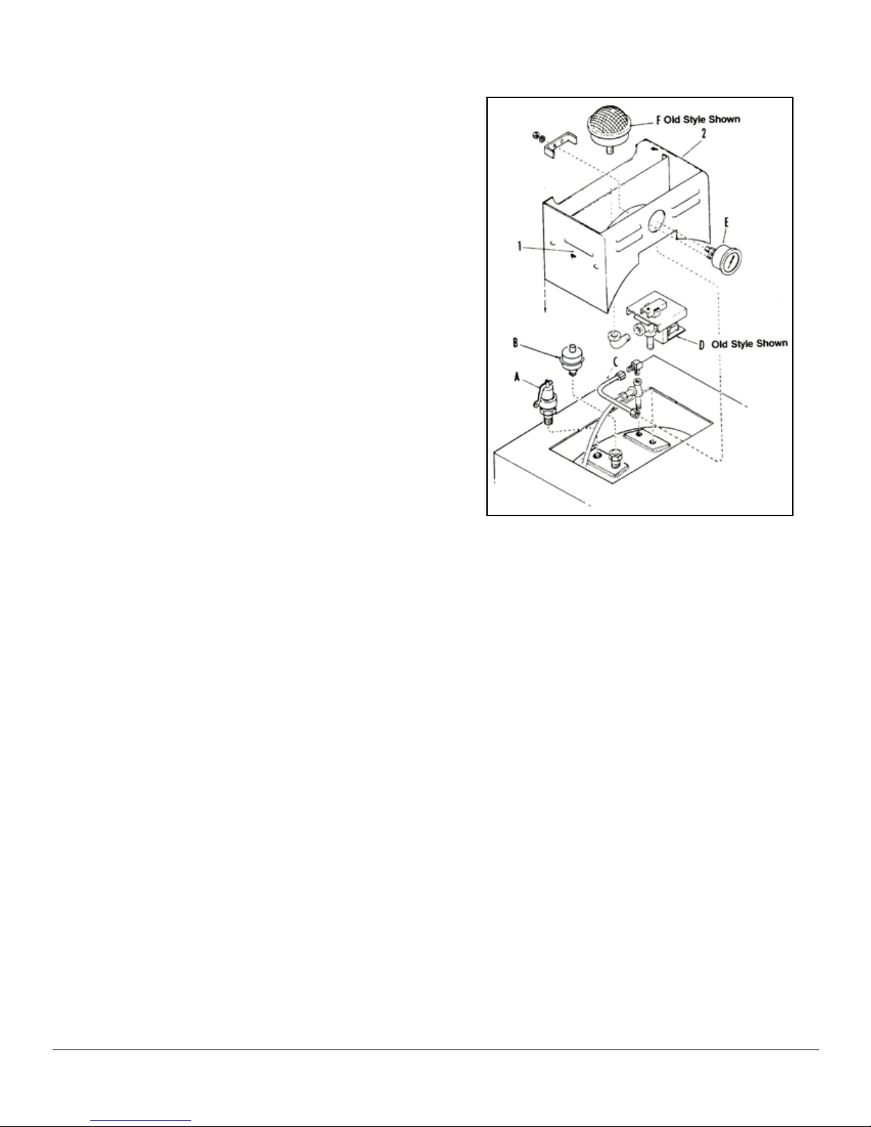
LOW WATER CUT-OFF
The low water cut-off is mounted above the timer assem-
bly under the front lower panel with its thermostat bulb ex-
tending and inserting into a channel provided for it at the
outer edge of the cast-in heating elements. It functions as
a safety feature to shut off the complete unit in the event
the water runs dry.
If the steam-it operated with no water or the water has
evaporated away, the temperature of the cooking cylinder
will rise and by heat inductions effect the thermostat bulb
of the low water cut-off. Electric current ow will b broken
at the low water cut-off and the unit will shut down. With
the replacement of water into the cooking cylinder, the
thermostat bulb will be cooled and the unit will then again
be operative after the reset button has been pressed.
If the unit does not start after pressing the reset button,
more time will have to be allowed for further cooling.
NOTE: Should a cooking cycle be started with insufcient
water and interrupted due to safety action of the
low water cut-off, the food in the process of cook-
ing will be affected. Proper compensation will
have to be made for the cooking performed and
with proper amount of water in the cooking cylin-
der, a new cycle determined and set to complete
the process.
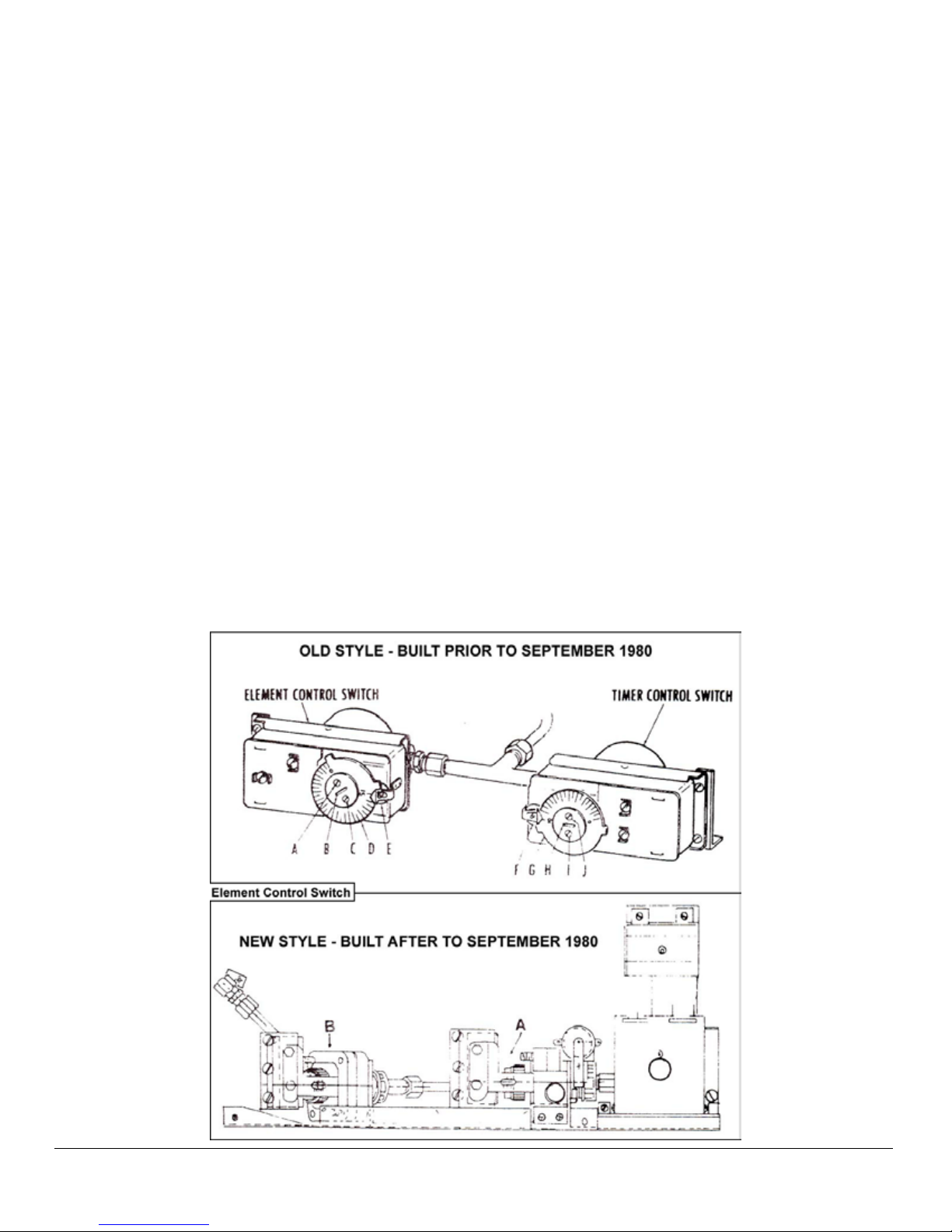
TIMER CONTROL SWITCH
The timer control switch located under the removable
front lower panel just right of center, automatically delays
the timer count-down at the beginning of the cycle until
the Steam-It has fully free-vented out all the cold air from
within the cooking cylinder and pressure has reached 10
PSI. This delay insures the timer to count only that por-
tion of the cycle when cylinder steam pressure is actually
acting on the foods. This, of course, is important when
processing foods which only require very short periods of
cooking time.
The copper tube which extends from the top of the cyl-
inder to the rear portion of the timer control switch con-
stantly reects internal cylinder steam pressure upon the
timer control switches build-up bellows. While cylinder
free-venting is occurring the switch keeps the timer circuit
open. After free-venting has terminated and when the cyl-
inder pressure has built up to approximately 10 PSI, the
contacts will be forces closed by back-pressures working
on the bellows, the timer circuit will be completes and the
timer will then start its countdown.
Adjustments
The cut-in point of the timer control switch has been facto-
ry set at its maximum setting of 10 lbs., and should not be
altered unless its found that the timer does not start until
well after 10 lbs. of steam pressure has been realized on
the pressure gauge. In this case, insert a screw driver into
the center slot (H) of the larger dial (G) and rotate slightly
counterclockwise to adjust timer to start at 10 PSI.
Recalibrating
Should the timer control switch vary through usage from
its original factory setting, it may be restored to proper
working order by recalibrating. A visual check of the timer
control switch during a trial cycle will quickly determine
the need of recalibration. With the timer control switch dial
set at 10 lbs., (fully clockwise) the timer motor should cut-
in when 10 lbs. of steam pressure is registered on the
steam pressure gauge. By watching the smaller dial (F)
on the timer control switch, the cut-in of the switch may
be observed and heard to click forward at the moment the
circuit is made to the timer motor. At that precise moment
the pressure gauge should read 10 lbs.
1. Set the larger dial (G) of the timer control switch to 10
lbs., (fully clockwise).
2. Loosen the two screws (I) and (J) located on either
side of the dial slot (H).
3. First, note the position of the slot (H) in relation to
4. the dial (G). then while holding the dial stationary, in-
sert a screwdriver into the slot and rotate slightly to
adjust (Clockwise- increase pressure, counterclock-
wise-decrease pressure). Tighten the two screws (I)
and (J) to hold this adjustment.
5. Check the unit through a trial cycle and note the pres-
sure gauge reading when the timer control switch is
observed and heard to click forward. Pressure read-
ing should then be at 10 lbs., (check also may be
made by continuity) readjust if necessary.
SAFETY VALVE
The safety valve is set to automatically relieve the cook-
ing compartment of excessive pressure build-up by open-
ing at a point between 15.5 lbs. and 16 lbs. If the safety
valve should leak continually with a pressure build-up, or
should it cause an interruption of the cooking cycle pre-
maturely (less then 15.5 lbs., on steam gauge) it must be
determined to be defective and be replaced. However, the
steam gauge should rst be checked for accuracy before
making this determination. The steam gauge should reg-
ister absolute zero setting with no pressure in the cooking
cylinder. If the normal zero setting has advanced some-
what through usage (a characteristic of steam gauges)
the amount of advancement from absolute zero must be
subtracted from its registered reading to determine the
true steam pressure.