Marklin Digital 60842 User manual

Decoder m84
60842
12345678910
ON
1234
12 3 45 6 78
T
F
D
GB
NL

2
D
GB
Bestimmungsgemäße Verwendung 4
Sicherheitshinweise 4
Wichtige Hinweise 4
Betriebshinweise 4
Einstellen der Adresse am Schalter 5
Elektrischer Anschluss 6
Kontrolllampen 6
Anschluss Hobby Signal 7
Anschluss externer Kontaktgeber 7
Betrieb unter MM (Motorola) 8
Grundsätzliche Einstellungen 8
Betrieb unter DCC 9
Programmieren am Programmiergleis 9
Grundsätzliche Einstellungen 9
Programmieren einer Adresse 9
Betrieb unter mfx 10
CV 79 – Voreingestellter Betriebsmodus 10
Adresstabelle 11
Using the Product as Intended 12
Safety Notes 12
Important Notes 12
Information about operation 12
Setting the Address with the Switches 13
Electrical Connections 14
Monitor Lights 14
Connections for the Hobby Signal 15
Connections for External Contact Generators 15
Operation with MM (Motorola) 16
Factory Setting 16
Operation with DCC 17
Programming on the Programming Track 17
Basic Settings 17
Programming an Address 17
Operation with mfx 18
CV 79 – Preset Operating Mode 18
Table of adresses 19

3
F
NL
Utilisation conforme à sa destination 20
Remarques sur la sécurité 20
Information importante 20
Remarques sur l’exploitation 20
Réglage de l’adresse sur le commutateur 21
Raccordement électrique 22
Voyants de contrôle 22
Raccordement du signal Hobby 23
Raccordement de contacteurs externes 23
Fonctionnement au format MM (Motorola) 24
Paramètre Usine 24
Fonctionnement au format DCC 25
Modifiée avec de la voie de programmation 25
Paramètres de base 25
Programmation d’une adresse 25
Exploitation sous mfx 26
CV 79 – Mode d’exploitation prédéfi ni 26
Tableau des adresses 27
Verantwoord gebruiken 28
Veiligheidsvoorschriften 28
Belangrijke aanwijzing 28
Opmerkingen over de werking 28
Instellen van het adres met de schakelaars 29
Elektrische aansluiting 30
Controlelampen 30
Aansluiten van het hobby sein 31
Aansluiten van externe contactgever 31
Bedrijf met MM (Motorola) 32
Fabriesinstelling 32
Bedrijf met DCC 33
Gemodificeerd met het programmeerspoor 33
Basisinstellingen 33
Programmeren van een adres 33
Bedrijf met mfx 34
CV 79 – Vooringestelde bedrijfsmodus 34
Adrestabel 35

4
Bestimmungsgemäße Verwendung
• Der Decoder m84 ist zum Gebrauch für digitale Modellei-
senbahnen mit den Digitalsystemen Motorola (MM), mfx
oder DCC bestimmt.
• Decoder ist geeignet zum Ein- und Ausschalten von
Dauerstrom für Beleuchtungen, Halteabschnitten als
Signalersatz und anderes elektrisches Zubehör.
Sicherheitshinweise
• Die Spannungsversorgung des m84 erfolgt ausschließlich
über den Gleisanschluss oder über das Schaltnetzteil
66360 (nur in Verbindung mit 60822).
• Anschlussarbeiten am Decoder m84 dürfen nur im span-
nungslosen Zustand erfolgen.
• ACHTUNG! Funktionsbedingte scharfe Kanten und Spitzen.
• Das Gehäuse darf nicht geöffnet werden.
• Der Decoder m84 ist ausschließlich zum Gebrauch in
trockenen Räumen bestimmt.
Wichtige Hinweise
• Die Bedienungsanleitung ist Bestandteil des Produktes
und muss deshalb aufbewahrt sowie bei Weitergabe des
Produktes mitgegeben werden.
• Für Reparaturen wenden Sie sich bitte an Ihren Märklin-
Fachhändler.
• Gewährleistung und Garantie gemäß der beiliegenden
Garantieurkunde.
• Entsorgung: www.maerklin.com/en/imprint.html
1 Dipschalter zur Einstellung der Adresse
2 Anschlussbuchse für 66360 (nur in Verbindung mit 60822)
3 Stecker und Buchsen zur direkten Verbindung mehrerer
Decoder m83/m84
4 Anschlussklemmen zum Anschluss ans Fahrgleis
5 Anschlussklemmen für die Verbraucher
6
Anschlusskontakt für die Lichtsignale 74371, 74391 und 74380
7 Anschlussklemmen für externe Taster bzw. Schaltkontakte
8 Schalter für Beleuchtung Hobby-Signal, werkseitg an.
deut.
12345678910
ON
12 3 45 6 78
T
1
2
333
3
4
5
6
7
8
Betriebshinweise
Bei Spannungsabfall (Kurzschluss) an den Klemmen (4)
werden alle Relais auf „aus“ gestellt. Nach Beseitigen
der Störung werden die Relais in die ursprüngliche Lage
zurückgestellt.
Bei externer Stromversorgung (2) bleibt die Lage der Relais
erhalten.

5
Mit dem Decoder m84 können bis zu 4 Verbraucher
unabhängig voneinander digital geschaltet werden. Dazu
benötigt der Decoder eine Adresse. Diese kann wahlweise
über den von außen zugänglichen Dip-Schalter oder per
Programmierung von Ihrem Steuergerät aus eingestellt
werden. Wir empfehlen dringend, die Einstellung über den
Dipschalter vorzunehmen.
Einstellen der Adresse am Schalter
An dem Decoder m84 können bis zu 4 Verbraucher ange-
schlossen werden. Eingestellt wird die Adresse des ersten
Verbrauchers. Die 3 weiteren Verbraucher bekommen
automatisch die entsprechenden Folgeadressen.
An dem Dip-Schalter sind insgesamt 10 einzelne Schalter.
Die Adresse wird mit den Schaltern 1 bis 9 eingestellt (der
Schalter 10 ist zur Auswahl des Digital-Protokolls, MM / DCC).
Der mit den Schaltern eingestellte Zahlenwert ergibt die
Adresse der ersten angeschlossenen Verbraucher.
Die Tabelle auf Seite 11 zeigt die Schalterstellungen für die
Adressen 1 – 160.
Hinweis: Bevor die Dip-Schalter verändert werden, muss
der Decoder komplett stromlos sein, d.h. dass auch die evtl.
angeschlossene externe Stromversorgung ausgeschaltet
werden muss.
Beispiel:
die Schalter 3 und 4 sind ON, alle anderen nicht:
4 + 8 = 12 Werte der Schalter addieren
-> Gruppenadresse 12
12 x 4 - 3 = 45 Errechnen der Einzeladresse
-> Einzeladressen 45 – 48
Die 4 angeschlossenen Verbraucher haben die Einzeladres-
sen 45 bis 48.
12345678910
ON
0/1
0/2
0/4
0/8
0/16
0/32
0/64
0/128
0/256
MM/DCC

6
Elektrischer Anschluss
Der Decoder m84 benötigt nur den Anschluss an den Fahr-
strom (Gleis) und an die Verbraucher. Zusätzlich kann der
Decoder an das Schaltnetzteil 66360 (nur in Verbindung mit
60822) angeschlossen werden (die Leistung wird dann nicht
vom Fahrgleis genommen – das Fahrgleis wird dadurch
entlastet).
Für den elektrischen Anschluss des Decoders und auch der
Verbraucher an den Decoder müssen die Kabelenden ab
isoliert und verdrillt, aber nicht verzinnt werden. Vor dem
Anschließen der Kabelenden an die Schraubklemmen sind
diese zunächst aufzuschrauben.
Mit den seitlichen Steckkontakten können mehrere
Decoder m83/m84 zusammengesteckt werden. Es dürfen
hierzu keine Verlängerungs- oder Verbindungskabel
verwendet werden. Alle zusammengesteckten Decoder
werden dann zusammen von der Stromversorgung und
dem Gleisanschluss des ersten Decoders versorgt. Es
darf kein weiterer Gleisanschluss erfolgen.
Kontrolllampen
• Ist der m84 richtig angeschlossen, blinkt eine Kontroll-
lampe.
• Die zweite Kontrolllampe blinkt einmal kurz auf, wenn der
Decoder angesprochen wird, d.h. wenn er schaltet oder
programmiert wird.
• Wenn beide Kontrolllampen am Anschluss schnell blin-
ken, wurden das rote und braune Kabel vertauscht.
• Die Kontrolllampen an den Verbraucherausgängen zeigen
den aktuellen Schaltzustand an.
12345678910
ON
AC/DC
12-18V Fahrgleis
Halteab-
schnitt
Halteab
-
schnitt
1234
12 3 45 6 78
T
Anschluss für 66360+60822
Fahrgleis
B 0
deut.

7
12345678910
ON
AC/DC
12-18V Fahrgleis
Halteab-
schnitt
Halteab
-
schnitt
12
34
12 3 45 6 78
T
Anschluss für 66360+60822
Fahrgleis
B 0
Anschluss Hobby Signal
Anschluss des Halteabschnittes
und des Fahrgleises gemäß
nebenstehender Skizze.
Anschluss externer Kontaktgeber
Die Eingänge 1 - 8 sind zum Schalten der Ausgänge des
M 84. Dort können Schaltgleise, Reedkontakte oder
Stellpulte direkt angeschlossen werden. Voraussetzung
ist, dass die Kontaktgeber mit dem braunen Kabel (0) des
Fahrstromes verbunden sind.
12345678910
ON
1234
12 3 45 6 78
T
Anschluss für 66360+60822
B 0
0
Zuordnung der Schalteingänge:
gemeinsame Zuleitung aller Kontaktgeber.
Das Schaltgleis benötigt keinen gesonderten (0) Anschluss,
es ist in die Gleisanlage eingebunden.
Die Eingänge 1 - 8 schalten die Verbraucher/Lichtsignale 1 - 4.
Verbraucher 1 = wird von 1 rot und 2 grün geschaltet
Verbraucher 2 = wird von 3 rot und 4 grün geschaltet
Verbraucher 3 = wird von 5 rot und 6 grün geschaltet
Verbraucher 4 = wird von 7 rot und 8 grün geschaltet
Wenn kein Hobby Signal ange-
schlossen wird, empfehlen wir
den Schalter (8) zur Reduzierung
des Stromverbrauches aus zu
schalten.
12345678910
ON
12 3 45 6
78
T
1
2
333
3
4
5
6
7
8ein
7

8
Betrieb unter MM (Motorola)
Für den Betrieb des m84 unter MM muss der Dip-Schalter 10
auf „OFF“ stehen.
Der Decoder kann nun unter den vorher eingestellten
Adressen angesprochen und geschaltet werden. Die Kon-
trollleuchten des Decoders zeigen den Schaltzustand der
Ausgänge an (grün / rot).
Grundsätzliche Einstellungen
CV Bezeichnung Wert
8 Reset 8
38 Licht Hobbysignal 0=aus / 1-10 = Helligkeit 0 – 10
79 Voreingestellter Betriebsmodus
(siehe Seite 10) 0 – 4
Die Vorgehensweise beim Programmieren mit der Control
Unit 6021 entspricht der Lokprogrammierung
(www.maerklin.de -> Service -> Technische
Informationen).
Zusätzlich externer Leistungsversorgung mit 66360 + 60822
und Anschluss für das Digitalsignal.
12345678910
ON
123456 7 8 910
ON
12345678910
ON
m83m84 m84
12345678910
ON
123456 7 8 910
ON
m83m84 m84
12345678910
ON
12 3 45 6 78
T
12 3 45 6 78
T
12 3 45 6 78
T
12 3 45 6 78
T
Anschluss Leistungsversorgung und Digitalsignal.
12345678910
ON
123456 7 8 910
ON
12345678910
ON
m83m84 m84
12345678910
ON
123456 7 8 910
ON
m83m84 m84
12345678910
ON
12 3 45 6 78
T
12 3 45 6 78
T
12 3 45 6 78
T
12 3 45 6 78
T

9
Grundsätzliche Einstellungen
CV Bedeutung Wert
1 Adresse (unterer Teil) 0 – 63
8 Reset 8
9 Adresse (oberer Teil) 0 – 7
38 Licht Hobbysignal 0=aus / 1-10 = Helligkeit 0 – 10
79 Voreingestellter Betriebsmodus
(siehe Seite 10) 0 – 4
Programmieren einer Adresse
Um unter DCC eine Adresse zu programmieren, müssen
2 CVs eingestellt werden (CV1; CV9). Eingestellt wird die
Weichengruppenadresse. Die Weicheneinzeladressen
errechnen sich gleich wie beim Einstellen der Adresse mit
den Dip-Schaltern.
W.-Gruppenadresse = CV1 + (CV9 x 64)
Beispiel:
CV1 = 15, CV9 = 3 ->
W.-Gruppenadresse: 15 + (3 x 64) = 207
W.-Einzeladressen: 207 x 4 - 3 = 825
Die Weichen haben die Weicheneinzeladressen 825 bis 828.
Betrieb unter DCC
Für den Betrieb des m84 unter DCC muss der Dip-Schalter
10 auf „ON“ stehen.
Die angeschlossenen Verbraucher können nun unter
der eingestellten Adresse angesprochen und geschaltet
werden. Die Kontrollleuchten des Decoders zeigen den
Schaltzustand der Weichen an (grün / rot).
Programmieren am Programmiergleis
Soll die Adresse selbst über Programmierung geändert
werden, so muss der Decoder am Programmiergleis ange-
schlossen werden und die Dip-Schalter 1 bis 9 auf „OFF“
stehen – der Decoder kann dann programmiert werden.

10
Betrieb unter mfx
Die mfx-Anmeldung kann unter MM oder DCC erfolgen.
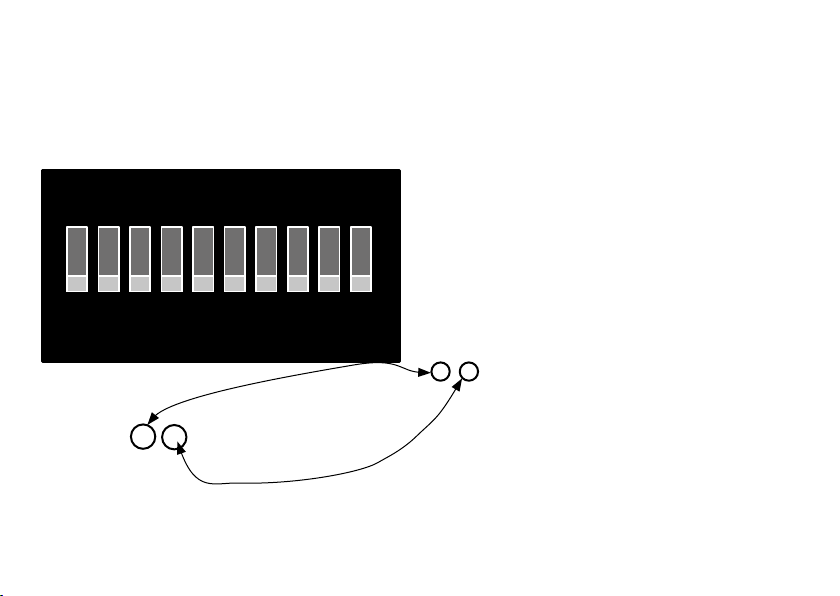
Entscheidend ist die eingestellte Betriebsart über den Dip-
Schalter 10.
Die mfx-Anmeldung wird mit der CS2 60213/60214/60215 in
der Magnetartikelkonfiguration über > und mit der
CS3 60216/60226 in der Magnetartikelkonfiguration über
>„mfx-Artikel suchen“ angestoßen.
Hinweis zur mfx-Anmeldung mit der CS2:
Auswahlmöglichkeit „Magnetartikel automatisch zuweisen“
unter „Setup“ > > „Gleis“.
Ist dort das Häkchen gesetzt erfolgt die mfx-Anmeldung auf
die ersten freien Adressen in der CS2.
Ist das Häkchen nicht gesetzt, erfolgt die mfx-Anmeldung
auf die tatsächlich am Decoder programmierten Adressen.
CV 79 - Voreingestellter Betriebsmodus
Mit den voreingestellten Betriebsmodi ist es möglich,
den Decoder in einen vordefinierten Betriebsmodus zu
versetzen, ohne alle CV-Variablen einzeln programmieren zu
müssen. Der Decoder agiert dann als Häuserbeleuchtung,
Straßenbeleuchtung etc.
Modus 0 (Wert 0) - Standardmodus
Der Decoder belegt in dieser Betriebsart 4 Adressen.
Dieser Modus ist der Auslieferungszustand. Realisiert den
bekannten m84 Umschaltmodus.
Modus 1 (Wert 1) - 8 Schalter, 4 Adressen
Modus-Funktion nur mit Märklin-Zentralen gewährleistet.
Der Decoder belegt in dieser Betriebsart 4 Adressen. Das
Schalten der Ausgänge erfolgt durch Momenttaster (gleiche
Taste für ein und aus). Ein Ausgang wird durch den roten
Momenttaster gesteuert, der grüne Momenttaster steuert
den zweiten Ausgang.
Modus 2 (Wert 2) - 8 Schalter, 8 Adressen
Der Decoder belegt in dieser Betriebsart 8 Adressen. Das
Schalten der Ausgänge erfolgt mittels Rot-Grün-Schalter.
Rot schaltet den Ausgang aus, Grün schaltet den Ausgang
ein.
Modus 3 (Wert 3) - Blinken und Zufall, 8 Adressen
Der Decoder belegt in dieser Betriebsart 8 Adressen. Das
Schalten der Ausgänge erfolgt mittels Rot-Grün-Schalter.
Rot schaltet den Ausgang aus, Grün schaltet den Ausgang
ein. Der Decoder realisiert diverse Blinkfunktionen zur Simu-
lation von Warnblinkern oder Werbetafelbeleuchtung.
Modus 4 (Wert 4) - Zufalls Häuserbeleuchtung, 8 Adressen
Der Decoder belegt in dieser Betriebsart 8 Adressen. Das
Schalten der Ausgänge erfolgt mittels Rot-Grün-Schalter.
Rot schaltet den Ausgang aus, Grün schaltet den Ausgang
ein. Der Decoder realisiert diverse Zufallsfunktionen zum
Beleuchten von Häusern.

11
Einzelad-
ressen
Dip-Schalter
123456789
1 – 4 1 — — — — — — — —
5 – 8 — 1 — — — — — — —
9 – 12 1 1 — — — — — — —
13 – 16 — — 1 — — — — — —
17 – 20 1 — 1 — — — — — —
21 – 24 — 1 1 — — — — — —
25 – 28 1 1 1 — — — — — —
29 – 32 — — — 1 — — — — —
33 – 36 1 — — 1 — — — — —
37 – 40 — 1 — 1 — — — — —
41 – 44 1 1 — 1 — — — — —
45 – 48 — — 1 1 — — — — —
49 – 52 1 — 1 1 — — — — —
53 – 56 — 1 1 1 — — — — —
57 – 60 1 1 1 1 — — — — —
61 – 64 — — — — 1 — — — —
65 – 68 1 — — — 1 — — — —
69 – 72 — 1 — — 1 — — — —
73 – 76 1 1 — — 1 — — — —
77 – 80 — — 1 — 1 — — — —
Einzelad-
ressen
Dip-Schalter
123456789
81 – 84 1 — 1 — 1 — — — —
85 – 88 — 1 1 — 1 — — — —
89 – 92 1 1 1 — 1 — — — —
93 – 96 — — — 1 1 — — — —
97 – 100 1 — — 1 1 — — — —
101 – 104 — 1 — 1 1 — — — —
105 – 108 1 1 — 1 1 — — — —
109 – 112 — — 1 1 1 — — — —
113 – 116 1 — 1 1 1 — — — —
117 – 120 — 1 1 1 1 — — — —
121 – 124 1 1 1 1 1 — — — —
125 – 128 — — — — — 1 — — —
129 – 132 1 — — — — 1 — — —
133 – 136 — 1 — — — 1 — — —
137 – 140 1 1 — — — 1 — — —
141 – 144 — — 1 — — 1 — — —
145 – 148 1 — 1 — — 1 — — —
149 – 152 — 1 1 — — 1 — — —
153 – 156 1 1 1 — — 1 — — —
157 – 160 — — — 1 — 1 — — —

12
Using the Product as Intended
• The m84 decoder is designed for use for digital model
railroads with the Motorola (MM), mfx, or DCC digital
systems.
• This decoder is designed to turn continuous current on
and off for lighting, stop blocks in the track as a substitute
for signals, and other electrical accessories.
Safety Notes
• Voltage for the m84 comes exclusively through track con-
nections or from the 66360/66365 switched mode power
pack (only in conjunction with 60822).
• Connections to the m84 decoder may only be done with
no voltage is present.
• IMPORTANT! The m84 has sharp edges and points due to
its function.
• The housing may not be opened.
• The m84 decoder is designed for use in dry areas only.
Important Notes
• The operating instructions are a component part of
this product and must therefore be kept safe as well as
passed on with the product to third parties.
• Please see your authorized Märklin dealer for repairs.
• The warranty card included with this product specifies
the warranty conditions.
• Disposing: www.maerklin.com/en/imprint.html
Information about operation
In the event of a drop-off in voltage (short circuit) at the
terminals (4) all of the relays are set to “off”. After the
12345678910
ON
12 3 45 6 78
T
1
2
333
3
4
5
6
7
8
1 Dip switches for setting the address
2 Connection socket for 66360 (230V) /66365 (120 V) (only in
conjunction with 60822)
3 Plugs and sockets for direct connection of several
m83/m84 decoders
4 Set screw terminals for connections to the track
5 Set screw terminals for users
6 Contact connections for the 74371, 74391, and 74380 color
light signals
7
Set screw terminals for external buttons or switching contacts
8 Switches for the lighting on Hobby signals, delivered from
the factory on.
problem has been fixed, the relays are set back to their
original position.
When there is an external supply of current (2), the position
of the relays remains preserved.

13
Up to 4 users can be digitally controlled independently of
each other with the m84 decoder. To do this the decoder
needs an address. This can be set either with the externally
accessible dip switches or with programming from your
controller. We strongly recommend setting the address with
the dip switches.
Setting the Address with the Switches
Up to 4 users can be can be connected to the m84 decoder.
The address of the first user is set. The other 3 users
automatically are assigned the corresponding sequential
addresses after this address.
There are 10 individual dip switches. The address is set with
switches 1 to 9 (switch 10 is for selecting the digital protocol
MM / DCC). The number value set with the switches gene-
rates the address for the first user connected to the decoder
The table on page 19 shows the switch settings for addres-
ses 1 – 160.
Note: There must be no current present in the decoder
before changing the dip switch settings. This means that
any external current supply connected to the decoder must
be turned off.
Example:
Switches 3 and 4 are ON, all of the others are off:
4 + 8 = 12 Adding the values of the switches
-> Group Address 12
12 x 4 - 3 = 45 Calculating the individual address
->
Individual addresses 45 – 48
The 4 users connected to the decoder have the individual
addresses 45 to 48.
12345678910
ON
0/1
0/2
0/4
0/8
0/16
0/32
0/64
0/128
0/256
MM/DCC

14
Electrical Connections
The m84 decoder only requires connections to the track cur-
rent and to the users. The decoder can also be connected
to the 66360/66365 switched mode power pack (only in con-
junction with 60822) (here power is not taken from the track
and the power demanded from the track is thereby less).
Strip insulation from the ends of the wires from the users
to the decoder and from the power supply to the decoder.
Twist these ends, but do not tin these ends with solder.
The set screws on the terminals must be loosened before
connecting the ends of the wires to them.
Several m83/m84 decoders can be plugged together with
the side plug contacts. No extension or connecting wire
may be used for this. All decoders plugged together are then
supplied with power from the power supply and the track
connection for the first decoder. No other track connections
may be made.
Monitor Lights
• If the m84 is connected correctly, a monitor light will
blink.
• The second monitor light blinks briefly one time when
the decoder is addressed, i.e. when it is switched or
programmed.
• If both monitor lights at the connections blink rapidly, then
the red and the brown wires were mistakenly swapped.
• The monitor lights at the switching outputs display the
current status of the circuit being switched.
12345678910
ON
AC/DC
12-18V Fahrgleis
Halteab-
schnitt
Halteab
-
schnitt
1234
12 3 45 6 78
T
Anschluss für 66360+60822
Fahrgleis
B 0
Connection for 66360/66365 + 60822
Stopping
Area
Stopping
Area
Track Track

15
12345678910
ON
AC/DC
12-18V Fahrgleis
Halteab-
schnitt
Halteab
-
schnitt
12
34
12 3 45 6 78
T
Anschluss für 66360+60822
Fahrgleis
B 0
Connections for the Hobby Signal
Stopping
Area Track
The nearby diagram shows the
connections for the signal block
and the regular track.
Connections for External Contact Generators
Inputs 1 - 8 are for switching the outputs on the M 84. Circuit
tracks, reed switches, or control boxes can be connected
directly to these inputs. A requirement is that the contact
generators must be connected with the brown wire (0) for
the locomotive operating current.
12345678910
ON
1234
12 3 45 6 78
T
Anschluss für 66360+60822
B 0
0
Assignment of the switching inputs:
Common wire to all contact generators.
The circuit track requires a special (0) connection; it is
connected in the track layout.
Inputs 1 - 8 switch users / color light signals 1 - 4.
User 1 = is switched by 1 red and 2 green
User 2 = is switched by 3 red and 4 green
User 3 = is switched by 5 red and 6 green
User 4 = is switched by 7 red and 8 green
If no Hobby signals are con-
nected, we recommend turning
the switch off (8) to reduce the
current consumption.
12345678910
ON
12 3 45 6
78
T
1
2
333
3
4
5
6
7
8ein
7
Connection for 66360/66365 + 60822

16
Operation with MM (Motorola)
Dip switch 10 must be set at “OFF“ for operation of the m84
with MM.
The decoder can now receive commands and be switched
at the address previously set. The status lights on the deco-
der indicate the switching status at the outputs (green / red).
Factory Setting
CV Description Value
8 Reset 8
38 Hobby color light signal 0 = off / 1-10 =
brightness 0 – 10
79 Preset Operating Mode
(See Page 18) 0 – 4
The procedure for programming with the 6021 Control Unit is
analogous to the programming for locomotives
(www.maerklin.de -> Service -> Technische Informationen).
Additional external power supply with 66360/66365 + 60822
and connections for the digital signal.
Connections for the power supply and digital signal.
12345678910
ON
123456 7 8 910
ON
12345678910
ON
m83m84 m84
12345678910
ON
123456 7 8 910
ON
m83m84 m84
12345678910
ON
12 3 45 6 78
T
12 3 45 6 78
T
12 3 45 6 78
T
12 3 45 6 78
T
12345678910
ON
123456 7 8 910
ON
12345678910
ON
m83m84 m84
12345678910
ON
123456 7 8 910
ON
m83m84 m84
12345678910
ON
12 3 45 6 78
T
12 3 45 6 78
T
12 3 45 6 78
T
12 3 45 6 78
T

17
Basic Settings
CV Meaning Value
1 Address (lower part) 0 – 63
8 Reset 8
9 Address (upper part) 0 – 7
38 Hobby color light signal 0 = off / 1-10 =
brightness 0 – 10
79 Preset Operating Mode
(See Page 18) 0 – 4
Programming an Address
Two CVs (CV1; CV9) must be set in order to program an
address in DCC. The turnout group address is set. The
individual turnout addresses are generated in the same way
as when setting the address with the dip switches.
Turnout group address = CV1 + (CV9 x 64)
Example:
CV1 = 15, CV9 = 3 ->
Turnout group address: 15 + (3 x 64) = 207
Individual turnout addresses: 207 x 4 - 3 = 825
Turnouts have the individual turnout addresses 825 to 828.
Operation with DCC
Dip switch 10 must be set at “ON“ for operation of the m84
with DCC.
The users connected to the decoder can now receive
commands and be switched at the address that has been
set. The status lights on the decoder indicate the switching
status at the outputs (green / red).
Programming on the Programming Track
If the address itself is to be changed by means of program-
ming, then the decoder must be connected to the program-
ming track and the dip switches 1 to 9 must be set at “OFF”
– the decoder can then be programmed.

18
Operation with mfx
mfx registration can be done with MM or DCC.The mode of
operation that has been set by means of Dip Switch 10 is
critical.
The mfx registration is initiated with the 60213/60214/60215
CS2 in > and with the 60216/60226 CS3 in the solenoid
item configuration by means of >“search for mfx item“.
Note about mfx registration with the CS2:
Selection possibility „Automatically assign solenoid item“ at
„Setup“ > > „Track“.
If the check mark there is checked, the mfx registration is
done at the first open address in the CS2.
If the check mark is not checked, the mfx registration is
done at the address actually programmed on the decoder.
CV 79 – Preset Operating Mode
With the preset operating modes, it is possible to move the
decoder into a pre-defined operating mode without having
to program all of the CV variables individually. The decoder
then operates as building lighting, street lighting, etc.
Mode 0 (Value 0) – Standard Mode
In this mode of operation, the decoder occupies 4 addresses.
This is the mode as delivered from the factory. Executes the
familiar m84 switching mode.
Mode 1 (Value 1) – 8 Switches, 4 Addresses
Mode function ensured only with Märklin central unit
controllers.
In this mode of operation, the decoder occupies 4 addres-
ses. Switching the outputs is done by means of momentary
buttons (same button for on and off). An output is controlled
by the red momentary button, and the green momentary
button controls the second output.
Mode 2 (Value 2) – 8 Switches, 8 Addresses
In this mode of operation, the decoder occupies 8 addres-
ses. Switching the outputs is done by means of red/green
buttons. Red switches the output off and green switches the
output on.
Mode 3 (Value 3) – Blinking and Random, 8 Addresses
In this mode of operation, the decoder occupies 8 addres-
ses. Switching the outputs is done by means of a red/green
button. Red switches the output off and green switches the
output on. The decoder executes various blinking functions
to simulate blinking warning lights or billboard lights.
Mode 4 (Value 4) – Random Building Lighting, 8 Addresses
In this mode of operation, the decoder occupies 8 addres-
ses. Switching the outputs is done by means of a red/green
button. Red switches the output off and green switches the
output on. The decoder executes various random functions
for lighting buildings.

19
Individual
Addresses
Dip Switches
123456789
1 – 4 1 — — — — — — — —
5 – 8 — 1 — — — — — — —
9 – 12 1 1 — — — — — — —
13 – 16 — — 1 — — — — — —
17 – 20 1 — 1 — — — — — —
21 – 24 — 1 1 — — — — — —
25 – 28 1 1 1 — — — — — —
29 – 32 — — — 1 — — — — —
33 – 36 1 — — 1 — — — — —
37 – 40 — 1 — 1 — — — — —
41 – 44 1 1 — 1 — — — — —
45 – 48 — — 1 1 — — — — —
49 – 52 1 — 1 1 — — — — —
53 – 56 — 1 1 1 — — — — —
57 – 60 1 1 1 1 — — — — —
61 – 64 — — — — 1 — — — —
65 – 68 1 — — — 1 — — — —
69 – 72 — 1 — — 1 — — — —
73 – 76 1 1 — — 1 — — — —
77 – 80 — — 1 — 1 — — — —
Individual
Addresses
Dip Switches
123456789
81 – 84 1 — 1 — 1 — — — —
85 – 88 — 1 1 — 1 — — — —
89 – 92 1 1 1 — 1 — — — —
93 – 96 — — — 1 1 — — — —
97 – 100 1 — — 1 1 — — — —
101 – 104 — 1 — 1 1 — — — —
105 – 108 1 1 — 1 1 — — — —
109 – 112 — — 1 1 1 — — — —
113 – 116 1 — 1 1 1 — — — —
117 – 120 — 1 1 1 1 — — — —
121 – 124 1 1 1 1 1 — — — —
125 – 128 — — — — — 1 — — —
129 – 132 1 — — — — 1 — — —
133 – 136 — 1 — — — 1 — — —
137 – 140 1 1 — — — 1 — — —
141 – 144 — — 1 — — 1 — — —
145 – 148 1 — 1 — — 1 — — —
149 – 152 — 1 1 — — 1 — — —
153 – 156 1 1 1 — — 1 — — —
157 – 160 — — — 1 — 1 — — —

20
Utilisation conforme à sa destination
• Le décodeur m84 est destiné à être utilisé pour les trains
miniatures digitalisés avec les systèmes numériques
Motorola (MM), mfx ou DCC.
• Le décodeur permet la mise en circuit ou hors circuit
sous courant permanent d’éclairages, sections d’arrêt
remplaçant un signal et autres accessoires électriques.
Remarques sur la sécurité
• Le décodeur m84 est alimenté exclusivement par la
jonction ou le convertisseur continu-continu 66360
(uniquement avec 60822).
• Les travaux de raccordement sur le décodeur m84
doivent être effectués uniquement hors tension.
• ATTENTION ! Pointes et bords coupants lors du fonction-
nement du produit.
• Le boîtier ne doit pas être ouvert.
• Le décodeur m84 est conçu exclusivement pour un usage
dans un endroit sec.
Information importante
• La notice d’utilisation fait partie intégrante du produit ;
elle doit donc être conservée et, le cas échéant, transmi-
se avec le produit.
• Pour toute réparation, adressez-vous à votre détaillant-
spécialisé Märklin.
• Garantie légale et garantie contractuelle conformément
au certificat de garantie ci-joint.
• Elimination : www.maerklin.com/en/imprint.html
12345678910
ON
12 3 45 6 78
T
1
2
333
3
4
5
6
7
8
1 Commutateur DIP pour le réglage de l’adresse
2
Douille de raccordement pour 66360 (uniquement avec 60822)
3 Fiches et douilles pour le raccordement direct de plu-
sieurs décodeurs m83/m84
4 Bornes pour le raccordement à la voie de roulement
5 Bornes de connexion pour les consommateurs
6
Contact pour les signaux lumineux réf. 74371, 74391 et 74380
7 Bornes de connexion pour interrupteurs externes resp.
contacteurs
8 Commutateur pour éclairage signal Hobby mis en place
en usine
Remarques sur l’exploitation
En cas de chute de tension (court-circuit) au niveau des bornes
(4), tous les relais sont positionnés sur « off ». Après élimination
de la panne, les relais reviennent dans leur position initiale.
Dans le cas d’une alimentation en courant externe (2), la
position des relais est conservée.
Table of contents
Languages:
Other Marklin Digital Media Converter manuals