10 Betrieb • Operation • Fonctionnement • Exploitatie
Remarques importantes sur la sécurité
• Lalocomotivenepeutêtremiseenservicequ’avecunsystème
d’exploitation adéquat (DC = 18V ±, Märklin AC, Märklin Digital ou
Märklin Systems).
• Utiliseruniquementdesconvertisseursettransformateurscorre-
spondant à la tension du secteur local.
• Lalocomotivenepeutêtrealimentéeencourantqueparuneseule
source de courant.
• Veuillezimpérativementrespecterlesremarquessurlasécurité
décrites dans le mode d’emploi de votre système d’exploitation.
• Pourl’exploitationdelalocomotiveenmodeconventionnel,lavoie
deraccordementdoitêtredéparasitée.Aceteffet,utiliserlesetde
déparasitage réf. 104770. Le set de déparasitage ne convient pas
pour l’exploitation en mode numérique.
• Nepasexposerlemodèleàunensoleillementdirect,àdefortes
variations de température ou à un taux d‘humidité important.
• ATTENTION! Pointes et bords coupants lors du fonctionnement du
produit.
Information importante
• Lanoticed‘utilisationfontpartieintégranteduproduit;ilsdoiventdonc
êtreconservéset,lecaséchéant,transmisavecleproduit.
• Pourtouteréparationouremplacementdepièces,adresses-vousà
votre détaillant-spécialiste Märklin.
• Garantielégaleetgarantiecontractuelleconformémentaucerticat
de garantie ci-joint.
• http://www.maerklin.com/en/imprint.html
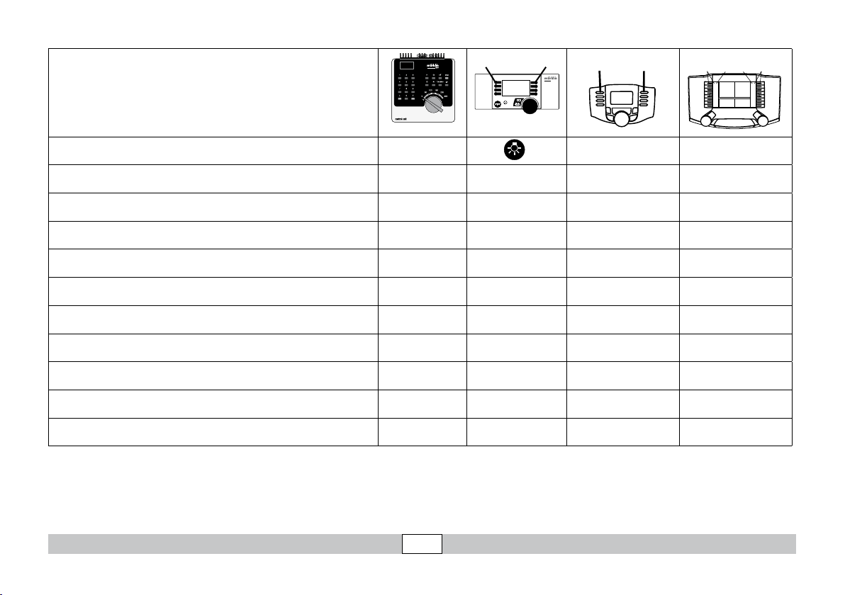
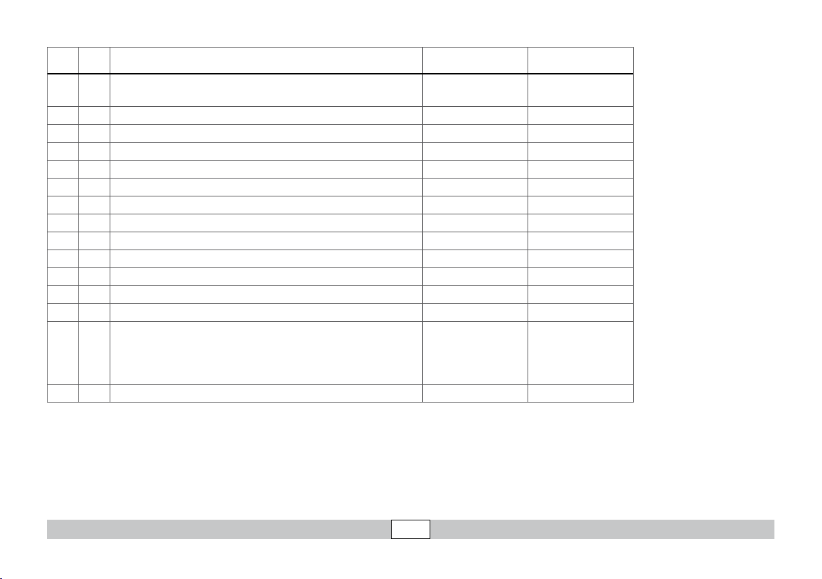
Fonctionnement
• Lemoded’exploitation(AC/DC,Mfx,Märklin-MotorolaouDCC)est
identiéautomatiquement.
• Adressesdisponibles:
1-80 (Control Unit 6021/Mobile Station 60651/652)
1-255 (Central Station 6021x/Mobile Station 60653)
• Adressedépartusine:(Märklin) 35 / (DCC) 03
• TechnologiemfxpourMobileStation/CentralStation.
Nomencodéeenusine:BR 335 105-3
• Temporisationd’accélérationréglable(ABV).
• Temporisationdefreinageréglable(ABV).
• Vitessemaximaleréglable.
• Paramétrerlesparamètresdeslocomotives(adresse,retardement
au démarrage / au freinage, vitesse maximale etc.) avec Control Unit
et DCC (programmation CV), Mobile Station ou Central Station.
• Feuxdesignalisationavecinversionselonsensdemarche.
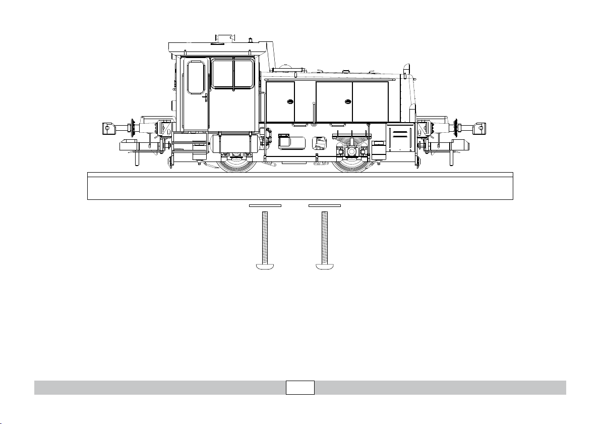
• LemodèleréduitestconçupourroulersurdesvoiesMärklin1.Le
faire rouler sur des voies d’autres systèmes comporte des risques.
• Rayonminimald’inscriptionencourbe:1020mm.
• AttelagesàgriffeMärklinavantetarrière.Encasd’utilisation
d’un système provenant d’un autre fabricant, des problèmes sont
susceptibles de survenir.
• Enmoded’exploitationanalogique,seuleslesfonctionsrelativesà
la conduite et à l‘inversion des feux sont disponibles.