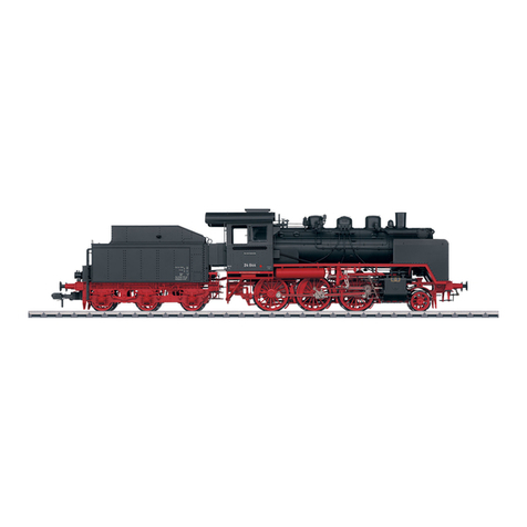
marklin 55424 User manual

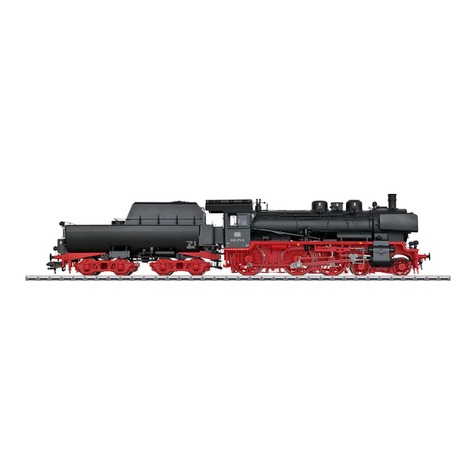
Modell der Schlepptender-Dampflok BR 042
55424

2
Inhaltsverzeichnis: Seite
Informationen zum Vorbild 4
Inbetriebnahme 6
Sicherheitshinweise 12
Wichtige Hinweise 12
Funktionen 12
Schaltbare Funktionen 13
Parameter / Register 14
Betrieb auf der Anlage 36
Wartung und Instandhaltung 42
Ersatzteile 44
Table of Contents: Page
Information about the prototype 4
Putting into Operation 6
Safety Notes 16
Important Notes 16
Functions 16
Controllable Functions 17
Parameter / Register 18
Operation on a layout 36
Service and maintenance 42
Spare parts 44
Sommaire : Page
Informations concernant la locomotive réelle
5
Mise en service 6
Remarques importantes sur la sécurité 20
Information importante 20
Fonctionnement 20
Fonctions commutables 21
Paramètre / Registre 22
Exploitation sur réseau 36
Entretien et maintien 42
Pièces de rechange 44

3
Indice de contenido: Página
Puesta en servicio 7
Aviso de seguridad 28
Notas importantes 28
Funciones 28
Funciones posibles 29
Parámetro / Registro 30
Funcionamiento del sistema 36
El mantenimiento 42
Recambios 44
Inhoudsopgave: Pagina
Informatie van het voorbeeld 5
Ingebruikname 7
Veiligheidsvoorschriften 24
Belangrijke aanwijzing 24
Functies 24
Schakelbare functies 25
Parameter / Register 26
Bedrijf op een modelbaan 36
Onderhoud en handhaving 42
Onderdelen 44
Indice del contenuto: Pagina
Messa in esercizio 7
Avvertenze per la sicurezza 32
Avvertenze importanti 32
Funzioni 32
Funzioni commutabili 33
Parametro / Registro 34
Exploitation sur réseau 36
Manutenzione ed assistere 42
Pezzi di ricambio 44

4
Vorbild • Prototype Exploitation dans le réelle • Grootbedrijf
Informationen zum Vorbild
Im Rahmen des Einheitslokprogramms der DRG entwickelte die Loko-
motivindustrie für schnellfahrende Güterzüge die 1’D1’-Lokomotive der
Baureihe 41. Die beiden Baumustermaschinen lieferte Schwartzkopff
1936. Das Fahrwerk war eine Neuentwicklung, der Kessel war der glei-
che wie bei der Baureihe 03, allerdings wurde er bei der BR 41 für 20
bar ausgelegt. Die Radsatzfahrmasse konnte wahlweise auf 18 t oder
20 t eingestellt werden. Mit der Baureihe 41 entstand erstmals eine
universell einsetzbare Mehrzwecklokomotive. Den beiden Vorserien-
maschinen folgten 364 Serienlokomotiven, die geringfügig verbessert
und von nahezu allen deutschen Lokomotivfabriken bis 1941 geliefert
wurden. Die 90 km/h schnellen und rund 1.900 PS starken Lokomotiven
kamen in fast allen Bereichen zum Einsatz.
Nach dem Zweiten Weltkrieg blieben 216 Loks bei der DB, 116 bei der
DR. Da beide Staatsbahnen auf die Baureihe 41 nicht verzichten konn-
ten, wurden zahlreiche Maschinen mit neuen Kesseln versehen. Als
Ersatz für die verschlissenen St47K-Kessel entwickelte die DB einen
vollständig geschweißten Hochleistungskessel mit Verbrennungskam-
mer. Gegenüber dem bisherigen Langrohrkessel hatte dieser einen
höheren Anteil an hochwertiger Strahlungsheizfläche und konnte somit
höher belastet werden. Zwischen 1957 und 1961erhielten im Ausbes-
serungswerk (AW) Braunschweig 102 Loks der Baureihe 41 diesen
neuen Kessel, der in Verbindung mit der entfallenen Frontschürze das
Erscheinungsbild der 41er deutlich veränderte. 40 dieser Umbauloks
kamen zusätzlich in den Genuss einer Ölhauptfeuerung.
Die nicht umgebauten Maschinen wurden größtenteils in den 1960er-
Jahren ausgemustert, bis 1971 folgten die rostgefeuerten Umbauma-
schinen, die ab 1968 als 041 bezeichnet wurden. Die ölgefeuerten 41er
(ab 1968: 042) hingegen standen bis zum Ende der Dampftraktion bei
der DB 1977 beim Bahnbetriebswerk Rheine im Einsatz.
Information about the prototype
The locomotive industry developed the class 41 2-8-2 locomotive for fast
freight trains as part of the DRG‘s standardized locomotive program.
Schwartzkopff delivered the two prototype units in 1936. The running
gear and frame was a new design. The boiler was the same as on the
class 03, but on the class 41 it was designed for 20 bar / 290 pounds per
square inch. The axle load could be set at 18 or 20 tons. The class 41 was
the first time for a universally applicable general-purpose locomotive.
The two prototype units were followed by 364 regular production loco-
motives that were improved slightly and that were delivered by almost all
German locomotive builders by 1941. These locomotives could run at 90
km/h / 56 mph and produced around 1,900 horsepower. They were used
in almost all areas.
After World War II 216 locomotives remained on the DB and 116 on
the East German DR. Since both state railroads could not do without
the class 41, numerous units were equipped with new boilers. The
DB developed an all-welded high-efficiency boiler with a combustion
chamber as a replacement for the worn out St47K boiler. Compared to
the previous long tube boiler, this boiler had a higher proportion of high
quality radiant heating surface and could thereby sustain a higher load.
Between 1957 and 1961, 102 class 41 locomotives were equipped with
this new boiler at the maintenance facility (AW) in Braunschweig. This
in conjunction with the discarded front skirting clearly changed the
look of the class 41 units.
The units not rebuilt were retired for the most part in the Sixties.
The rebuilt units fired with a grate followed by 1971. They had been
reclassified as the class 041 starting in 1968. The oil-fired class 41 units
(starting in 1968: 042) by contrast were in use and stationed at Rheine
until the end of steam motive power on the DB in 1977.

5
Vorbild • Prototype Exploitation dans le réelle • Grootbedrijf
Informations concernant la locomotive réelle
La locomotive de la série 41 1’D1’ (disposition d’essieux 141) fut conçue
dans le cadre du programme d’unification des locomotives de la DRG. Les
deux prototypes furent livrés par Schwartzkopff en 1936. Le châssis était de
conception nouvelle, la chaudière était la même que celle de la série 03, à
la différence que pour la BR 41, elle était prévue pour 20 bars. La charge par
essieu pouvait être réglée au choix sur 18 ou 20 t. La série 41 était la pre-
mière série de locomotives polyvalentes universelles. Les deux machines de
pré-série furent suivies de 364 locomotives de série légèrement améliorées
qui furent livrées jusqu’en 1941 par presque toutes les usines de locomotives
allemandes. Les locomotives, qui avec leurs 1900 ch pouvaient atteindre une
vitesse de 90 km/h, étaient utilisées dans presque tous les domaines.
Après la seconde guerre mondiale, 216 locomotives restèrent à la
DB et 116 à la DR. Ces deux compagnies ferroviaires ne pouvant se
passer de la série 41, de nombreuses machines furent pourvues d’une
nouvelle chaudière. Pour remplacer les chaudières St47K usées, la
DB conçut une chaudière haute performance entièrement soudée
avec chambre de combustion. Comparée à la chaudière à tubes longs
utilisée jusqu’alors, celle-ci présentait une plus grande surface de
chauffe à rayonnement très performante et supportait donc de plus
lourdes charges. Entre 1957 et 1961, 102 locomotives de la série 41
furent équipées dans l’atelier principal de Braunschweig de cette
nouvelle chaudière qui, avec la suppression du tablier frontal, modifiait
sensiblement l’apparence de la BR 41. Quarante de ces locomotives
transformées furent dotées en outre d’une chauffe principale au fuel.
Les machines non transformées furent en grande partie réformées dans
les années 1960, suivies jusqu’en 1971 par les machines transformées
avec grille de chauffe qui, à partir de 1968, furent immatriculées dans
la série 041. Les machines de la série 41 chauffées au fuel (désignées
comme série 042 à partir de 1968), affectées au dépôt de Rheine, restè-
rent par contre en service jusqu’en 1977, fin de la traction vapeur à la DB.
Informatie van het voorbeeld
In het kader van het eenheidslocprogramma van de DRG ontwikkelde
de locomotiefindustrie de 1’D1’-locomotief van de serie 41 voor snelle
goederentreinen. Beide prototypes werden in 1936 door Schwartzkopff
geleverd. Het onderstel was een nieuwe ontwikkeling, de ketel was
dezelfde als bij de serie 03, maar bij de BR 41 werd die voor 20 bar
gebouwd. De wielstelbelasting kon naar keuze op 18 ton of 20 ton wor-
den ingesteld. Met de serie 41 ontstond voor het eerst een universeel
inzetbare, multifunctionele locomotief. Na beide voorseriemachines
volgden 364 serielocomotieven, die lichtjes werden verbeterd en tot
1941 door nagenoeg alle Duitse locomotieffabrieken werden geleverd.
Deze locomotieven haalden 90 km/u en waren circa 1.900 pk sterk; ze
werden in vrijwel alle domeinen ingezet.
Na de Tweede Wereldoorlog bleven 216 locomotieven bij de DB en 116
bij de DR. Omdat beide staatsspoorwegen niet op de serie 41 konden
rekenen, werden vele machines met een nieuwe ketel uitgerust. Ter
vervanging van de versleten St47K-ketel ontwikkelde de DB een volle-
dig gelaste hoogrendementsketel met verbrandingskamer. In tegen-
stelling tot de voorheen gebruikte kokervormige ketel, had de nieuwe
ketel een groter aantal verwarmde stralingsoppervlakken, waardoor
die hoger kon worden belast. Tussen 1957 en 1961 kregen 102 loco-
motieven van de serie 41 deze nieuwe ketel in de reparatiewerf (AW)
Braunschweig, waardoor het uitzicht van de 41 duidelijk veranderde
gezien het frontschort nu was verdwenen. 40 van deze omgebouwde
locomotieven werden bovendien met een oliestookvoorziening uitge-
rust.
De niet-omgebouwde machines werden grotendeels in de jaren 60
buiten bedrijf gesteld, tot 1971 volgden de ombouwmachines op vaste
brandstof, die vanaf 1968 als 041 werden aangeduid. De oliegestookte
41 (vanaf 1968: 02) bleef daarentegen tot het einde van de stoomtractie
in 1977 bij de DB ingezet bij het spoorbedrijfdepot Rheine.
6
Betrieb • Operation • Fonctionnement Exploitatie • Operación • Operazione
Vor dem ersten Betrieb
Dieses Modell ist hinsichtlich der Technik
und er Ausführung besonders aufwändig und
hochwertig. Die meisten angesteckten oder
verbauten Teile sind aus Metall gefertigt.
Solche Teile können nicht so einfach ge-
tauscht werden, wie z.B. Kunststoffteile. Bitte
beachten Sie daher, dass Sie dieses Modell
besonders vorsichtig handhaben sollten.
Für den Tausch von Teilen oder Reparaturen
wenden Sie sich bitte an den Märklin Service.
Hinweise
• Das Modell muss vor dem ersten Betrieb
geschmiert werden (siehe Seite 42/43).
• Die Lok kann nicht ohne Tender betrieben
werden. Das Verbindungskabel zwischen
Lok und Tender muss sicher eingesteckt
sein (siehe Seite 10). Das Verbindungskabel
zwischen Lok und Tender darf nur im span-
nungslosen Zustand eingesteckt werden.
• Wenn das Modell mit aktivem Dampfgene-
rator betrieben wird, so kann ins Besondere
der durch die Zylinder ausströmende Dampf
die Gleise stark verschmutzen.
Before Operating for the First Time
This model is especially complex and costly
in terms of its technology. Most of the applied
parts are constructed of metal. Such parts
cannot be replaced so easily as for example
plastic parts. Please therefore note that you
should handle this model with special care.
Please contact Märklin Service for replace-
ment of parts or for repairs.
Notes
• This model must be lubricated before ope-
rating it for the first time (see page 42/43).
• This locomotive cannot be operated without
the tender. The connecting cable between
the locomotive and tender must be plugged
in securely (see page 10). The connecting
cable between the locomotive and tender
may be plugged in only when there is no
voltage present or on.
• When the model is operated with the smoke
generator on, especially the steam flowing
out of the cylinders can dirty up the track
greatly.
Avant la première mise en service
Ce modèle bénéficie d’une technicité de
haut niveau et d‘une finition particulièrement
soignée. La plupart des éléments rapportés
ou intégrés sont en métal. De tels éléments ne
se remplacent pas aussi facilement que des
éléments en plastique par exemple. Veillez
donc à manipuler ce modèle avec un soin
particulier.
Pour les pièces détaillées ou d’éventuelles
réparations, veuillez vous adresser au Service
Märklin.
Remarques
• Le modèle doit être graissé avant sa premi-
ère mise en service (voir page 42/43)
• La locomotive ne peut pas être exploitée
sans tender. Le câble de raccordement
entre la locomotive et le tender doit être
enfiché correctement (voir page 10). Le
câble de raccordement entre la locomotive
et le tender doit être branché hors tension
uniquement.
• Si le modèle est exploité avec un généra-
teur de fumée activé, la vapeur émise – et
particulièrement celle émanant des cylin-
dres – risque d‘encrasser sérieusement la
voie.

7
Betrieb • Operation • Fonctionnement Exploitatie • Operación • Operazione
Voor het eerste gebruik
Dit model is vanwege de techniek en de
uitvoering bijzonder uitgewerkt en hoogwaar-
dig uitgevoerd. De meeste opgestoken of
aangebouwde delen zijn van metaal gemaakt.
Dergelijke delen kunnen niet zo eenvoudig
vervangen worden dan kunststof delen. Let
er daarom op dat u het model uitermate voor-
zichtig behandelt.
Voor het vervangen van delen of reparaties
kunt u zich wenden tot het Märklin service
centrum.
Aanwijzingen
• Het model moet voor het eerste gebruik
gesmeerd worden (zie afb. 42/43)
• De loc kan niet zonder de tender gebruikt
worden. De verbindingskabel tussen loc en
tender moet op de juiste manier ingestoken
zijn (zie afb. 10). De verbindingskabel tussen
loc en tender mag alleen in spanningsloze
toestand er in gestoken worden.
• Als het model met de geactiveerde
dampgenerator gebruikt word, kan in het
bijzonder de door de cilinders uitgestoten
damp de rails sterk vervuilen.
Antes de la primera puesta en servicio
En los aspectos de tecnología incorporada y
ejecución, este modelo en miniatura es muy
sofisticado y avanzado. La mayoría de piezas
enchufadas o incorporadas son de metal.
Tales piezas no se pueden sustituir con la
facilidad de, p. ej., las piezas de plástico. Por
este motivo, tenga presente que debe mane-
jar este modelo con suma precaución.
Para la sustitución de piezas o para reparaci-
ones, diríjase al Servicio de Märklin.
Consejos
• Lubricar el modelo en miniatura antes de la
primera puesta en servicio (véase 42/43).
• No está permitido utilizar la locomotora sin
ténder. El cable de interconexión entre la
locomotora y el ténder debe estar enchufa-
do de modo seguro (véase página 10). Está
permitido enchufar el cable de intercone-
xión entre locomotora y ténder únicamente
sin tensión eléctrica presente.
• Si el modelo se utiliza con un generador de
vapor activo, en particular el vapor que sale
de los cilindros puede provocar un fuerte
ensuciamiento de las vías.
Prima del primo funzionamento
Questo modello è particolarmente complicato
e di alto pregio sotto l’aspetto della tecnolo-
gia e dell’esecuzione. La maggior parte degli
elementi applicati a innesto o riportati sono
realizzati di metallo. Tali componenti non pos-
sono venire sostituiti tanto facilmente, come
ad es. le parti di materiale sintetico. Vogliate
pertanto prestare attenzione, affinché Voi
maneggiate questo modello con particolare
cautela.
Per la sostituzione di componenti oppure
riparazioni, vogliate rivolgerVi al Servizio
Assistenza Märklin.
Avvertenza
• Tale modello deve venire lubricato prima
del primo funzionamento
(si veda pagina 42/43).
• Tale locomotiva non può venire messa in
funzione senza tender. Il cavetto di collega-
mento tra locomotiva e tender deve essere
innestato in modo sicuro (si veda pagina 10).
Il cavetto di collegamento tra locomotiva
e tender deve venire innestato solamente
nella condizione di assenza di tensione.
• Qualora tale modello venga fatto funzionare
con generatore di vapore attivo, special-
mente quel vapore che defluisce attraverso
i cilindri può allora imbrattare fortemente i
binari.

8
Betrieb • Operation • Fonctionnement Exploitatie • Operación • Operazione
Für den sicheren Transport wurde dieses
schwere Modell auf dem Sockel ange-
schraubt. Bitte transportieren Sie dieses
Modell nur trocken und so gesichert und in
der Originalkassette.
Beachten Sie, dass der Tender nach ent-
fernen der Sicherungsschrauben auf dem
Stellbrett frei rollen kann und gegen Absturz
gesichert werden muss.
This heavy model was bolted to the base for
safe transport. Please transport this model
only when it is dry and secured as described
in preceding sentence and in the original box.
Please note that the tender can roll free after
removing the mounting bolts on the base, and
it must therefore be protected against falling
and crashing.
Afin d’éviter tout problème lié au transport, ce
modèle lourd a été vissé sur son socle. Veillez
à le transporter uniquement sous cette condi-
tion, au sec et dans son boîtier d’origine.
Notez qu’une fois la vis de sécurité enlevée,
le tender peut rouler librement sur la planche
et qu‘il faut donc prévenir le risque de chute.
Voor een veilig transport is het model op een
sokkel vast geschroefd. Transporteer het
model a.u.b. alleen droog en vastgeschroefd
in de originele cassette.
Let er op dat de tender na het verwijderen
van de transportschroeven, op de sokkel vrij
kan rollen en vastgehouden moet worden om
vallen te voorkomen.
Para hacer posible un transporte seguro, se
ha atornillado este pesado modelo al zócalo.
Transporte este modelo en miniatura siempre
seco y bien asegurado y en su casete original.
Asegúrese de que el ténder, tras retirar los
tornillos inmovilizadores, pueda rodar libre-
mente sobre el pupitre de la maqueta y de
protegerlo contra el vuelco.
Per un trasporto sicuro questo pesante mo-
dello è stato fissato con viti al basamento. Si
prega di trasportare questo modello soltanto
asciutto e così assicurato, e nella cassetta
originale.
Prestate attenzione al fatto che il tender, dopo
la rimozione delle viti di fissaggio sulla tavo-
letta di appoggio, può correre liberamente e
deve venire assicurato contro la caduta.

9
Betrieb • Operation • Fonctionnement Exploitatie • Operación • Operazione

10
Betrieb • Operation • Fonctionnement Exploitatie • Operación • Operazione
1
Hinweis: Das Verbindungskabel zwischen
Lok und Tender darf nur im spannungslosen
Zustand eingesteckt werden. Stellen Sie die
Fahrzeuge dazu auf ein abgeschaltetes Gleis
oder schalten Sie die Anlage vorher ab.
Note: The connecting cable between the
locomotive and tender may be plugged in only
when there is no voltage present or on. To
do this, place the locomotive and tender on a
length of track with no power in it or shut the
layout off before doing this.
Remarque : Le câble de raccordement entre
la locomotive et le tender doit être branché
hors tension uniquement. Pour cela, placez
les véhicules sur un rail non alimenté ou
débranchez au préalable l’installation.
Nota: Está permitido enchufar el cable de
interconexión entre locomotora y ténder
únicamente sin tensión eléctrica presente.
Para tal fin, coloque los vehículos en una
vía con la alimentación eléctrica apagada o
apague previamente el suministro eléctrico a
la maqueta de trenes.
Avvertenza: Il cavetto di collegamento tra
locomotiva e tender deve venire innestato
solamente nella condizione di assenza di
tensione. A tale scopo vogliate collocare i
rotabili sopra un binario disattivato oppure in
precedenza disattivate l’impianto.
Opmerking: De verbindingskabel tussen loc
en tender mag alleen in spanningsloze
toestand er in gestoken worden. Zet het
voertuig hiervoor op een afgeschakeld spoor
of schakel de gehele baan voordien uit.

11
Betrieb • Operation • Fonctionnement Exploitatie • Operación • Operazione
2

12
Betrieb • Operation • Fonctionnement Exploitatie • Operación • Operazione
Sicherheitshinweise
• Die Lok darf nur mit einem dafür bestimmten Betriebssystem
(Gleichstrom [DC] = max 18V±, Märklin Wechselstrom,
Märklin Digital oder Märklin Systems) eingesetzt werden.
• Nur Schaltnetzteile/Transformatoren verwenden, die Ihrer örtlichen
Netzspannung entsprechen.
• Die Lok darf nur aus einer Leistungsquelle versorgt werden.
• Beachten Sie unbedingt die Sicherheitshinweise in der Bedienungs-
anleitung zu Ihrem Betriebssystem.
• Für den konventionellen Betrieb der Lok muss das Anschlussgleis
entstört werden. Dazu ist das Entstörset 104770 zu verwenden. Für
Digitalbetrieb ist das Entstörset nicht geeignet.
• Das verwendete Gleisanschlusskabel darf maximal 2 Meter lang sein.
• Setzen Sie das Modell keiner direkten Sonneneinstrahlung, starken
Temperaturschwankungen oder hoher Luftfeuchtigkeit aus.
• ACHTUNG! Funktionsbedingte scharfe Kanten und Spitzen.
• Verbaute LED`s entsprechen der Laserklasse 1 nach Norm EN 60825-1.
Wichtige Hinweise
• Wegen der hohen Leistungsaufnahme dieser Lokomotive ist der
Betrieb mit der Mobile Station 60652 nur eingeschränkt möglich.
• Die Bedienungsanleitung ist Bestandteil des Produktes und muss
deshalb aufbewahrt sowie bei Weitergabe des Produktes mitgege-
ben werden.
• Für Reparaturen oder Ersatzteile wenden Sie sich bitte an Ihren
Märklin-Fachhändler.
•
Gewährleistung und Garantie gemäß der beiliegenden Garantieurkunde.
• Entsorgung: www.maerklin.com/en/imprint.html
Funktionen
•
Die Betriebsart (AC/DC, Mfx, Märklin-Motorola oder DCC) wird
automatisch erkannt.
• Mfx-Technologie für Mobile Station / Central Station.
Name ab Werk: 042 096-8
• Einstellbare Adressen:
1-80 (Control Unit 6021)
1-255 (Central Station 6021x)
01 – 9999 DCC
• Adresse ab Werk: (Märklin) 42 & 43 / (DCC) 3
• Einstellen der Lokparameter (Adresse, Anfahr-/Bremsverzögerung,
Höchstgeschwindigkeit usw.): mit Control Unit und DCC (CV Pro-
grammierung), Mobile Station oder Central Station.
• Fahrtrichtungsabhängige Stirnbeleuchtung.
• Bei eingeschaltetem Rauch sind einzelne Rauchfunktionen zusam-
men mit den Geräuschfunktionen auslösbar (siehe Seite 39).
• Im Fahrbetrieb wird die Steuerstange auf der rechten Seite der Lok
über einen Motor vorbildgerecht in 5 Stellungen verstellt.
• Die Türen an Lok und Tender können durch die beiliegenden Türen
ersetzt werden (S. 36). Durch die größeren können Probleme im
Fahrbetrieb entstehen.
• Das Modell ist für den Betrieb auf Märklin 1-Gleisen entwickelt. Ein
Betrieb auf anderen Gleissystemen geschieht auf eigenes Risiko.
• Befahrbarer Mindestradius: 1020 mm
• Im Analogbetrieb stehen nur die Fahr- und Lichtwechselfunktionen
zur Verfügung.

13
Betrieb • Operation • Fonctionnement Exploitatie • Operación • Operazione
Schaltbare Funktionen
Digital/Systems
Spitzensignal function/off Funktion f0
Rauchgenerator (42) f1 Funktion f1
Betriebsgeräusch (42) f2 Funktion f2
Geräusch & Dampf1: Pfeife (42) f3 Funktion f3
Telex-Kupplung (42) f4 Funktion f4
Führerstandsbeleuchtung (43) f1 Funktion f5
Triebwerksbeleuchtung (43) f2 Funktion f6
Geräusch & Dampf: Rangierpfiff (43) f3 Funktion f7
ABV, aus (43) f4 Funktion f8
Geräusch: Bremsenquietschen aus — Funktion f9
Geräusch: Ölbrenner — Funktion f10
Geräusch: Glocke — Funktion f11
Geräusch: Luftpumpe — Funktion f12
Geräusch: Injektor — Funktion f13
Geräusch: Wasserpumpe — Funktion f14
Geräusch & Dampf1, 2: Zylinder ausblasen — Funktion f15
f0 f8 f0f8
1nur in Verbindung mit F1
2nur wenn Taste länger gedrückt bleibt

14
Betrieb • Operation • Fonctionnement Exploitatie • Operación • Operazione
CV Bedeutung Wert für 6021 Wert DCC
01 Adresse 01 – 80 (42) 1 – 127 (3)
CV 29/Bit 5 =0
02 PoM Minimalgeschwindigkeit — 0 – 255 (20)
03 PoM Anfahrverzögerung 01 – 63 0 – 255 (15)
04 PoM Bremsverzögerung 01 – 63 0 – 255 (15)
05 PoM Maximalgeschwindigkeit 01 – 63 0 – 255 (250)
08 Werkreset/Herstellerkennung 08 08 (131)
13 PoM Funktionen F1 - F8 im Analogbetrieb — 0 – 255 (0)
14 PoM Funktionen F9 - F15 und Licht im Analogbetrieb — 0 – 255 (1)
17 Erweiterte Adresse (oberer Teil CV29 Bit 5 =1) — 192 – 255 (192)
18 Erweiterte Adresse (unterer Teil CV29 Bit 5 =1) — 0 – 255 (128)
19 Traktionsadresse — 0 – 255 (0)
21 PoM Funktionen F1 - F8 bei Traktion — 0 – 255 (0)
22 PoM Funktionen F9 - F15 und Licht bei Traktion — 0 – 255 (0)
27 PoM Bit 4 = normales Bremsverhalten
Bit 5 = inverses Bremsverhalten — 0, 16, 32, 48 (48)
29 PoM
Bit 0: Umpolung Fahrtrichtung
Bit 1: Anzahl Fahrstufen 14 oder 28/128
Bit 2: Analogbetrieb ein/aus
Bit 5: Adressumfang 7 Bit / 14 Bit
—
0 / 1 (0)*
0 / 2 (2)*
0 / 4 (4)*
0 / 32 (0)*
50 PoM DC Vmax — 0 – 255 (255)
60 PoM
Multibahnhofsansage
Bit 0 – 3 = Anzahl der Bahnhöfe
Bit 4 = letzter Bahnhof kehrt Reihenfolge um
Bit 5 = Lokrichtung bestimmt Reihenfolge
Bit 6 = Reihenfolge Grundeinstellung
— 0 – 127 (1)

15
Betrieb • Operation • Fonctionnement Exploitatie • Operación • Operazione
( ) Werte = Werkseinstellung
DCC: programmieren auf dem Programmiergleis mittels CV Programmierung,
programmieren mit PoM (Program on the Main); dies muss vom Steuergerät unterstützt werden.
* Die Werte der gewünschten Einstellungen sind zu addieren!
Z.B. Anzahl der Fahrstufen 28/128 = 2 + DCC Betrieb mit Bremsstrecke = 4, ergibt Wert = 6
CV Bedeutung Wert für 6021 Wert DCC
63 PoM Lautstärke 01 – 63 (63) 0 – 255 (255)
64 PoM Bremsschwelle 0 – 255 (255)
75 Adresse 2 (1. Folgeadresse) 01 – 80 (43) —
138 PoM Lautstärke Sound „Bremsenquietschen“ — 0 – 255 (255)
139 PoM Lautstärke Sound „Betriebsgeräusch“ — 0 – 255 (255)
140 PoM Lautstärke Sound 1 (Pfeife) — 0 – 255 (255)
141 PoM Lautstärke Sound 2 (Rangierpfiff) — 0 – 255 (255)
142 PoM Lautstärke Sound 3 (Glocke) — 0 – 255 (255)
146 PoM Lautstärke Sound 7 (Wasserpumpe) — 0 – 255 (255)
147 PoM Lautstärke Sound 8 (Pfeife) — 0 – 255 (255)
150 PoM Lautstärke Sound 11 (Luftpumpe) — 0 – 255 (255)
151 PoM Lautstärke Sound 12 (Injektor) — 0 – 255 (255)
152 PoM Lautstärke Sound 13 (Zylinder ausblasen) — 0 – 255 (255)

16
Betrieb • Operation • Fonctionnement Exploitatie • Operación • Operazione
• The warranty card included with this product species the warranty
conditions.
• Disposing: www.maerklin.com/en/imprint.html
Functions
• The mode of operation (AC/DC, Mfx, Märklin Motorola, or DCC) is
recognized automatically.
• Mfx technology for the Mobile Station / Central Station.
Name set at the factory: 042 096-8
• Possible addresses:
1-80 (Control Unit 6021)
1-255 (Central Station 6021x)
01 – 9999 DCC
• Address set at the factory: (Märklin) 42 & 43 / (DCC) 3
• Setting locomotive parameters (address, acceleration/braking delay,
maximum speed, etc.): with the Control Unit and DCC (CV program-
ming), Mobile Station, or the Central Station.
• Headlights, changing over with the direction of travel.
• Individual smoke functions can be activated with the sound func-
tions when the smoke is turned on (see page 39).
• When the locomotive is running, the control rod on the right side of the
locomotive is shifted prototypically in 5 positions by means of a motor.
• The doors on the locomotive and the tender can be replaced by doo-
rs included with the model (Page 36). The larger doors may cause
problems when the locomotive is running.
• The model is designed for operation on Märklin 1 Gauge track. As the
consumer you assume the risk for operating on other makes of track.
• Minimum radius for operation: 1020 mm / 40-1/6“.
• Only the train control functions and headlight changeover feature
are available in analog operation.
Safety Notes
• This locomotive is to be used only with an operating system desi-
gned for it (DC power = 18V±, Märklin AC, Märklin Digital,
Märklin Systems).
• Use only switched mode power supply units and transformers that
are designed for your local power system.
• This locomotive must never be supplied with power from more than
one transformer.
• Pay close attention to the safety notes in the instructions for your
operating system.
• The feeder track must be equipped to prevent interference with
radio and television reception, when the locomotive is to be run in
conventional operation. The 104770 interference suppression set is
to be used for this purpose.
• The wire used for feeder connections to the track may only be a
maximum of 2 meters / 78 inches long.
• Do not expose the model to direct sunlight, extreme changes in
temperature, or high humidity.
• WARNING! Sharp edges and points required for operation.
• The LEDs in this item correspond to Laser Class 1 according to Stan-
dard EN 60825-1.
Important Notes
• Due to the high power requirements for this heavy locomotive, there
are only limited possibilities for operation with the 60652 Mobile Station.
• The operating instructions are a component part of the product and must
therefore be kept as well as transferred along with the product to others.
• Please see your authorized Märklin dealer for repairs or spare parts.

17
Betrieb • Operation • Fonctionnement Exploitatie • Operación • Operazione
Controllable Functions
Digital/Systems
Headlights function/off Function f0
Smoke generator (42) f1 Function f1
Operating sounds (42) f2 Function f2
Sound effect & steam1: whistle blast (42) f3 Function f3
Telex coupler (42) f4 Function f4
Engineer‘s cab lighting (43) f1 Function f5
Running gear lights (43) f2 Function f6
Sound effect & steam: Switching whistle (43) f3 Function f7
ABV; OFF (43) f4 Function f8
Sound effect: Squealing brakes off — Function f9
Sound effects of the oil burner — Function f10
Sound effect: Bell — Function f11
Sound effect: Air pump — Function f12
Sound effect: Injector — Function f13
Sound effect: Water pump — Function f14
Sound effect & steam1, 2: Blowing out cylinders — Function f15
f0 f8 f0f8
1only in conjunction with F1
2only when the button is pressed down longer

18
Betrieb • Operation • Fonctionnement Exploitatie • Operación • Operazione
CV Discription 6021 Value DCC Value
01 Address 01 – 80 (42) 1 – 127 (3)
CV 29/Bit 5 =0
02 PoM Minimum Speed — 0 – 255 (20)
03 PoM Acceleration delay 01 – 63 0 – 255 (15)
04 PoM Braking delay 01 – 63 0 – 255 (15)
05 PoM Maximum speed 01 – 63 0 – 255 (250)
08 Factory Reset / Manufacturer Recognition 08 08 (131)
13 PoM Functions F1 - F8 in analog operation — 0 – 255 (0)
14 PoM Functions F9 - F15 and lights in analog operation — 0 – 255 (1)
17 Extended address (upper part CV29 Bit 5 = 1) — 192 – 255 (192)
18 Extended address (lower part CV29 Bit 5 = 1) — 0 – 255 (128)
19 Multiple Unit Address — 0 – 255 (0)
21 PoM Functions F1 - F8 on Multiple Unit — 0 – 255 (0)
22 PoM Functions F9 - F15 and lights on Multiple Unit — 0 – 255 (0)
27 PoM Bit 4 = Normal braking behavior
Bit 5 = Inverse braking behavior — 0, 16, 32, 48 (48)
29 PoM
Bit 0: Reversing direction
Bit 1: Number of speed levels 14 or 28/128
Bit 2: analog operation on/off
Bit 5: Address length 7 Bit / 14 Bit
—
0 / 1 (0)*
0 / 2 (2)*
0 / 4 (4)*
0 / 32 (0)*
50 PoM DC Vmax — 0 – 255 (255)
60 PoM
Multiple station announcements
Bit 0 – 3 = Number of stations
Bit 4 = Last station reverses the sequence.
Bit 5 = Locomotive direction determines the sequence.
Bit 6 = Basic setting for sequence.
— 0 – 127 (1)

19
Betrieb • Operation • Fonctionnement Exploitatie • Operación • Operazione
( ) Values = factory settings
DCC: programming on the programming track by means of CV programming,
programming with PoM (Program on the Main); this must be supported by the controller you are using.
* The values for the desired setting must be added!
Example: The number of speed levels 28/128 = 2 + DCC operation with a braking route = 4, results in the value = 6
CV Discription 6021 Value DCC Value
63 PoM Volume 01 – 63 (63) 0 – 255 (255)
64 PoM Brake threshold 0 – 255 (255)
75 Address 2 (1st consecutive address) 01 – 80 (43) —
138 PoM Volume for sound "squealing brakes" — 0 – 255 (255)
139 PoM Volume for sound "operating sounds" — 0 – 255 (255)
140 PoM Volume for sound 1 (whistle) — 0 – 255 (255)
141 PoM Volume for sound 2 (Switching whistle) — 0 – 255 (255)
142 PoM Volume for sound 3 (Bell) — 0 – 255 (255)
146 PoM Volume for sound 7 (Water pump) — 0 – 255 (255)
147 PoM Volume for sound 8 (whistle) — 0 – 255 (255)
150 PoM Volume for sound 11 (Air pump) — 0 – 255 (255)
151 PoM Volume for sound 12 (Injector) — 0 – 255 (255)
152 PoM Volume for sound 13 (Blowing out cylinders) — 0 – 255 (255)

20
Betrieb • Operation • Fonctionnement Exploitatie • Operación • Operazione
Remarques importantes sur la sécurité
• La locomotive ne peut être mise en service qu’avec un système
d’exploitation adéquat (DC = 18V ±, Märklin AC, Märklin Digital ou
Märklin Systems).
• Utiliser uniquement des convertisseurs et transformateurs corre-
spondant à la tension du secteur local.
• La locomotive ne peut être alimentée en courant que par une seule
source de courant.
• Veuillez impérativement respecter les remarques sur la sécurité
décrites dans le mode d’emploi de votre système d’exploitation.
• Pour l’exploitation de la locomotive en mode conventionnel, la voie
de raccordement doit être déparasitée. A cet effet, utiliser le set de
déparasitage réf. 104770. Le set de déparasitage ne convient pas
pour l’exploitation en mode numérique.
• Le câble de raccordement à la voie utilisé ne doit en aucun cas
dépasser deux mètres.
• Ne pas exposer le modèle à un ensoleillement direct, à de fortes
variations de température ou à un taux d‘humidité important.
• ATTENTION! Pointes et bords coupants lors du fonctionnement du
produit.
• Les DEL installées correspondent à la classe laser 1 selon la
norme EN 60825-1.
Information importante
• Du fait de l’importance de la puissance absorbée de cette locomotive,
l’exploitation avec la Mobile Station 60652 n’est possible que dans cer-
taines limites.
• La notice d‘utilisation font partie intégrante du produit ; ils doivent donc
être conservés et, le cas échéant, transmis avec le produit.
• Pour toute réparation ou remplacement de pièces, adresses-vous à
votre détaillant-spécialiste Märklin.
• Garantie légale et garantie contractuelle conformément au certicat
de garantie ci-joint.
• Elimination : www.maerklin.com/en/imprint.html
Fonctionnement
• Le mode d’exploitation (AC/DC, Mfx, Märklin-Motorola ou DCC) est
identifié automatiquement.
• Technologie mfx pour Mobile Station / Central Station.
Nom encodée en usine : 042 096-8
• Adresses pouvant être paramétrées :
1-80 (Control Unit 6021)
1-255 (Central Station 6021x)
01 – 9999 DCC
• Adresse départ usine : (Märklin) 42 & 43 / (DCC) 3
• Paramétrer les paramètres des locomotives (adresse, retardement
au démarrage / au freinage, vitesse maximale etc.) avec Control Unit
et DCC (programmation CV), Mobile Station ou Central Station.
• Feux de signalisation avec inversion selon sens de marche.
• Une fois le générateur de fumée activé, les différentes fonctions
peuvent être déclenchées avec les fonctions sonores (voir page 39).
•
En mode d’exploitation, la bielle de commande est déplacée de manière
réaliste par un moteur sur le côté droit de la loco selon cinq positions.
• Les portes de la loco et du tender peuvent être remplacées par les
portes fournies (page 36), mais celles-ci peuvent être à l’origine de
problèmes importants lors de l’exploitation.
• Le modèle réduit est conçu pour rouler sur des voies Märklin 1. Le
faire rouler sur des voies d’autres systèmes comporte des risques.
• Rayon minimal d’inscription en courbe: 1020 mm.
• En mode d’exploitation analogique, seules les fonctions relatives à la
conduite et à l‘inversion des feux sont disponibles.
Table of contents
Other marklin Model Train manuals

marklin
marklin 55381 User manual

marklin
marklin 58013 User manual

marklin
marklin 55804 User manual

marklin
marklin 55182 User manual

marklin
marklin 260 V 60 User manual

marklin
marklin 55717 User manual

marklin
marklin 55247 User manual

marklin
marklin 55383 User manual

marklin
marklin 55388 User manual

marklin
marklin 55386 User manual

marklin
marklin 55716 User manual

marklin
marklin 55385 User manual

marklin
marklin 58016 User manual

marklin
marklin 58027 User manual

marklin
marklin 55414 User manual

marklin
marklin 58081 User manual

marklin
marklin 55963 User manual

marklin
marklin 55918 User manual

marklin
marklin 55184 User manual

marklin
marklin 55185 User manual