Marpo Kinetics VMX User manual

Marpo Kinetics, Inc.
258 LINDBERGH AVE, Livermore, A 94551 • (925) 606-6919 • www.marpokinetics.com
- VMX –
IMPORTANT
INFORMATION
TO SAFELY REMOVE PRODUCT
FROM THE PACKAGE,
FOLLOW THESE INSTRUCTIONS
FOR SAFETY, TWO OR MORE PEOPLE MUST ASSIST IN THE PACKAGE
REMOVAL AND PRODUCT INSTALLATION.
IT IS BEST THAT THE REMOVAL OF THE PRODUCT FROM THE PACKAGE, BE
DONE NEAR THE AREA WHERE THE PRODUCT WILL BE PLACED FOR USE.
THIS WILL ELIMINATE THE NEED TO MOVE THE PRODUCT AROUND AFTER
IT IS ASSEMBLED. SHOULD THERE BE A NEED TO MOVE THE PRODUCT,
THERE MUST ALWAYS BE AT LEAST TWO PEOPLE DOING THIS OPERATION
TO AVOID ANY INJURIES. TO PROTECT THE ROPE FROM SNAGS, IT MUST BE
KEPT WRAPPED UNTIL IT IS READY TO BE STRETCHED ONTO THE PULLEYS.
REMEMBER, ALWAYS KEEP ALL BODY PARTS AWAY FROM PULLEYS OR ANY
MOVING PARTS AS THESE ELEMENTS CAN CAUSE SERIOUS INJURY.
MINORS SHOULD NEVER BE ALLOWED TO OPERATE THE MACHINE WITHOUT
THE CONSENT AND CONSTANT SUPERVISION OF AN ADULT.
Securing Equipment
All MARPO e uipment must be secured to the floor to stabilize and eliminate rocking or
tipping. This must be performed by a licensed contractor. DO NOT use the e uipment if it
is not set up and located on a solid, level surface.
DO NOT install equipment on an uneven surface.
Use fasteners having a minimum of 500 lbs. tensile capacity (3/8" grade 2 bolts or better).
If legs/frame do not make contact with the ground, DO NOT pull down with anchors. Shim
any leg or frame not in contact with surface using flat washers.
1

Marpo Kinetics, Inc.
258 LINDBERGH AVE, Livermore, A 94551 • (925) 606-6919 • www.marpokinetics.com
1. Remove all wrapping material.
CAUTION: Do not use blades to cut wrapping material since it may damage the unit.
2. Remove all contents from the box:
1 MA N UN T
1 BOOM
1 STEP
1 ADUSTABLE REAR CROSS BAR
1 M D CROSS BAR
1 BENCH LEG
1 BENCH
1 SET (LEFT AND R GHT) COVERS FOR BOOM BASE
1 USER MANUAL
1 PACKAGE REMOVAL NSTRUCT ON
1 WORKOUT POSTER
2

Marpo Kinetics, Inc.
258 LINDBERGH AVE, Livermore, A 94551 • (925) 606-6919 • www.marpokinetics.com
3. One person should hold on to the MA N UN T while a second person should attach the
M D CROSS BAR to it using the provided 1/4-20 X 3” screws. Use a cardboard block
provided with the unit to prop up the unit while attaching the M D CROSS BAR. Have a
second person hold the unit from falling over while attaching the M D CROSS BAR. The
anti-skid tape of the M D CROSS BAR should be pointing to the ground. nsert screws
with 1” OD fender washer from the bottom up through the M D CROSS BAR so the
threads protrude from the M D CROSS BAR upwards. Fasten provided 0.25-20 nut onto
protruding thread.
CAUTION: Leaving the product unsupported before the unit is attached to the
MID CROSS BAR could cause the unit to fall over and cause injury and/or product
damage.
4. Attach the ADUSTABLE REAR CROSS BAR with the anti-skid tape pointing up and
adjust the two leveling feet until both touch the ground. nsert screws with 1” OD fender
washer from the bottom up through the ADJUSTABLE REAR CROSS BAR so the
threads protrude upwards. Fasten thread on top with 0.25” washer and 0.25-20 nylon nut.
Use the cardboard block again for wrench clearance.
5. As shown above & left, attach the BENCH LEG to the bottom holes on the 2 uprights of
the MA N UN T. Do NOT connect to the M D CROSS BAR. Leave the bolts loose until
the BENCH gets installed in the next step.
6. Now attach the BENCH to the MA N UN T. Ensure the nuts for this connection are on
the outside as shown above. This will protect the rope from getting snagged on the end
threads of the screws.
7. Connect the back end of the BENCH to the BENCH LEG as shown above/right. After
this connection is made tighten all screws for BENCH LEG and BENCH.
3
For BENCH connection to MA N UN T,
ensure the nuts are on the outside to
protect rope from getting damaged by the
threads on the end of the bolts

Marpo Kinetics, Inc.
258 LINDBERGH AVE, Livermore, A 94551 • (925) 606-6919 • www.marpokinetics.com
8. Connect HORSE SHOE as shown. Note orientation, the flat end of the horseshoe faces
the MA N UN T.
9. f the product rocks side-to-side or front to back, adjust the nuts on the 3 threaded
LEVEL NG FEET. Re-tighten the nuts after calibration.
10. Attach the ADJUSTABLE BOTTOM PULLEYS (W TH BRACKETS) to the MA N
UN T. Use provided screws (screws temporarily attached to the frame of the MA N
UN T).
11. nstall the STEP to the rear of the MA N UN T.
12. nstall the CARR AGE on the BOOM and then attach the BOOM CAP to the BOOM.
To install the CARR AGE, slide the 4 metal rollers of the CARR AGE inside the two
4
Boom
Cap
Carriage
Handle
Boom
connection
Step
Adjustable Bottom Pulleys
with Brackets
Covers for Boom
Base

Marpo Kinetics, Inc.
258 LINDBERGH AVE, Livermore, A 94551 • (925) 606-6919 • www.marpokinetics.com
barrels of the BOOM. Note the CARR AGE PULLEY orients to the front of the unit.
Remove the pulley from the CARR AGE and install the rope on it. Make sure rope is not
twisted when installing it on the CARR AGE. After the BOOM CAP is attached to the
BOOM, slide carriage to the bottom slot in the boom before proceeding. (Ropes with
plastic cap ends may be connected to carriage at a later time)
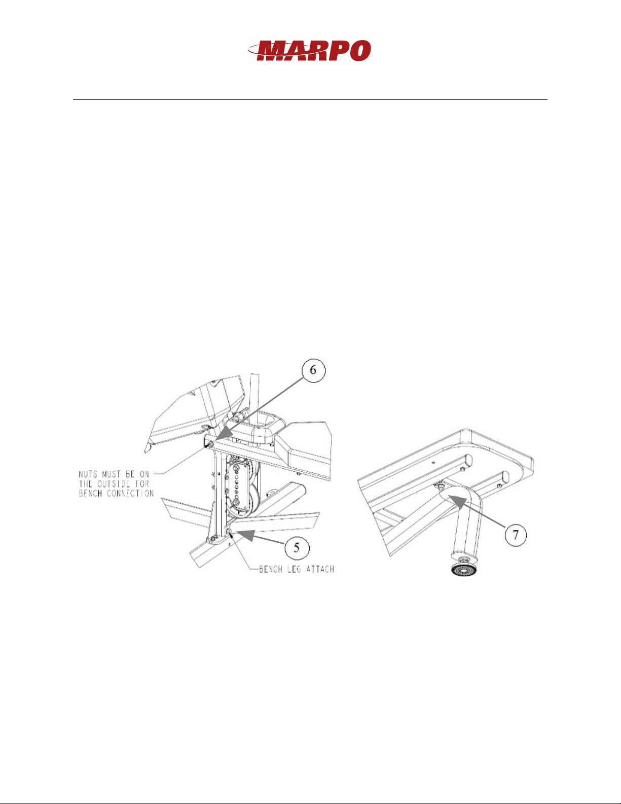
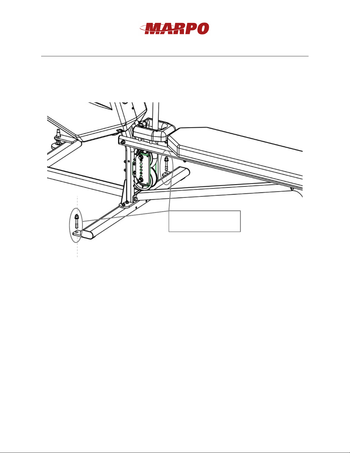
13. Connect the BOOM to the MA N UN T with the 3/8-16 bolts, nuts and washers. .
14. Connect the two PLAST C COVERS for Boom Base. Attach the small covers to the
main covers first. Afterwards, attach the top of the small cover to the boom with provided
screws on boom.
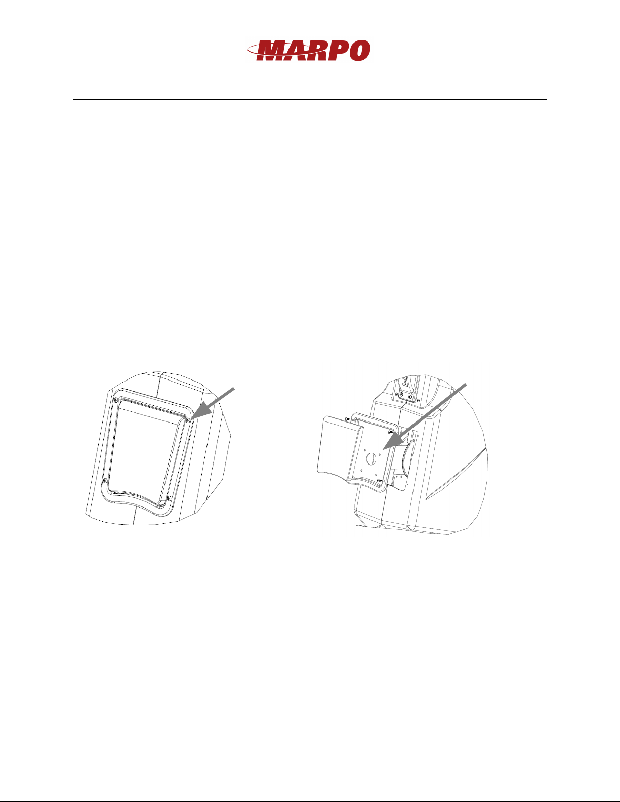
15. The electronic display works with two AAA batteries. To replace the batteries remove
the 4 screws that connect the D SPLAY TRAY to the main covers. Slowly pull the
D SPLAY TRAY away from the machine. Disconnect the display from the main
harness. Next remove the 4 machine screws that connect the D SPLAY to the the
D SPLAY TRAY to access the battery cover on the back of the D SPLAY.
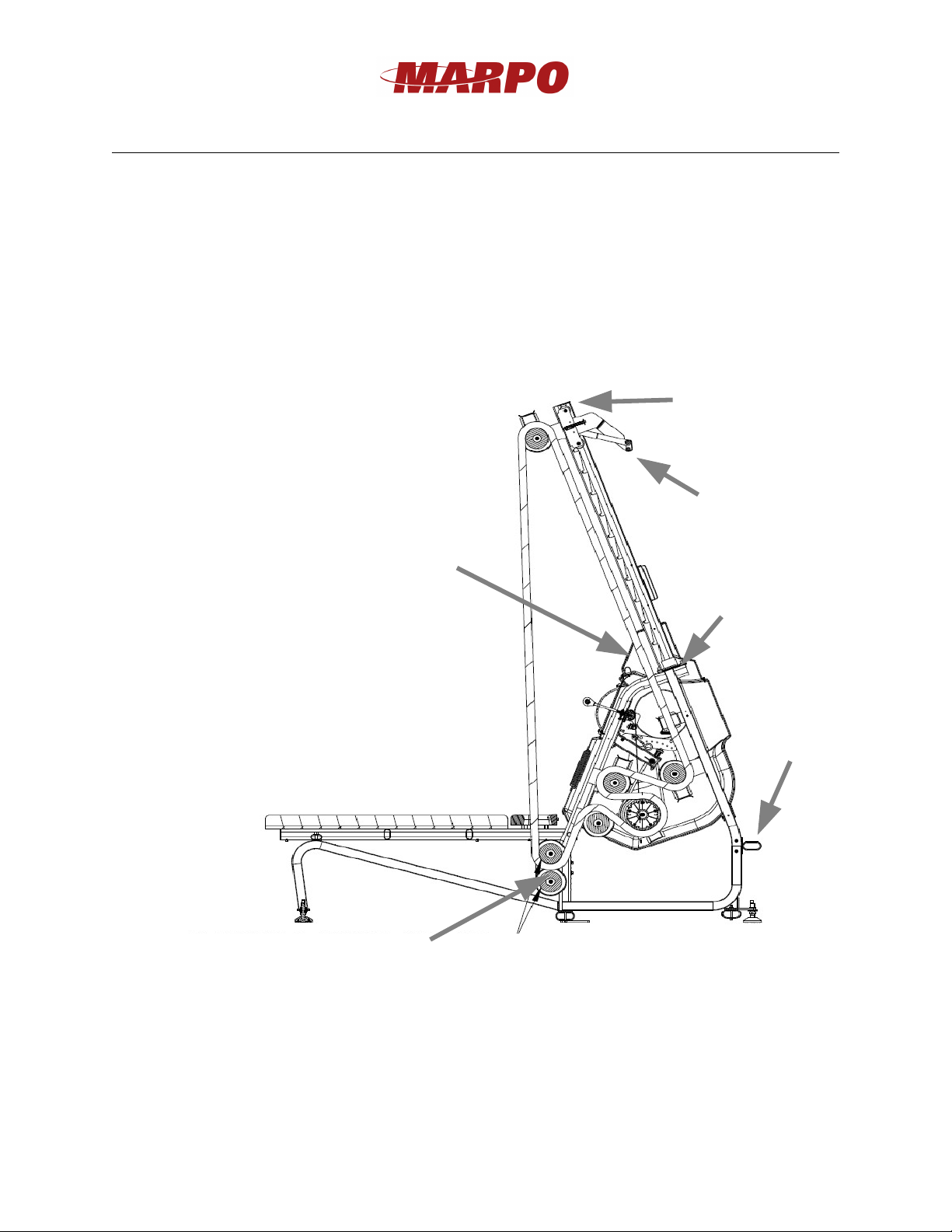
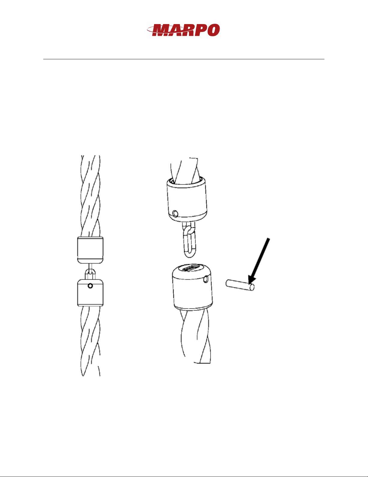
16. f the unit has black plastic end caps on the rope ends, pull end of the rope through the
BOOM and over the top of the CARR AGE PULLEY and the other end of the rope, pull
under and around the BOTTOM ROPE PULLEY and through the HORSE SHOE of the
BENCH to connect the two ends of the rope. See illustration on previous page for rope
routing diagram. Also see steps 18 and 19 for ends connection.
NOTE: the rope tends to tighten up during shipping so you may need to stretch it before
connecting the two ends. To do this hold the two ends of the rope and work the rope up
and down with a few pulls, to stretch it until the ends can reach each other. For optimal
unit performance, allow some slack in the rope after the two ends are connected. f
needed, the slack in the rope can be adjusted by moving the BOTTOM ROPE PULLEY
to a higher or lower set of holes.
5
Remove these
screws first and
watch out for the
harness as pulling
the display tray
away from the
main covers
Remove these
screws next to
access batteries.

Marpo Kinetics, Inc.
258 LINDBERGH AVE, Livermore, A 94551 • (925) 606-6919 • www.marpokinetics.com
17. f your unit has rope with plastic end cap connection follow these instructions to connect
the ends of the rope. Pin the chain link in the end cap with the provided
1/4-20 set screw. Before you install this screw ensure the rope is not twisted as this will
create kinks in the rope over time.
MPORTANT: YOU MUST LOCK THE ROPE CONNECT ON SET SCREW BY
PLAC NG A DROP OF SUPER GLUE ON THE LAST 3-4 THREADS OF THE
SCREW R GHT BEFORE YOU HAVE NSERTED T ALL THE WAY N THE
PLAST C END CAP. (see illustration below)
6
Rope ends
connection
Place a drop of
super glue here

Marpo Kinetics, Inc.
258 LINDBERGH AVE, Livermore, A 94551 • (925) 606-6919 • www.marpokinetics.com
18. Once the machine has been leveled off with the ground, drill the anchor rods provided
with the user manual at the specified locations in the picture below. Anchor rods must be
drilled into the concrete with a minimum embedment length of 2" for optimal
performance.
7
Anchor rod minimum
embedment length: 2”
Other manuals for VMX
3
Table of contents
Other Marpo Kinetics Fitness Equipment manuals
Popular Fitness Equipment manuals by other brands

Tuff stuff
Tuff stuff CVR-341 owner's manual

Lifepro
Lifepro THE SURGER Setup guide and user manual

TriStar
TriStar AbCoaster Quick and Easy Assembly Guide

Life Fitness
Life Fitness CLUB SERIES BACK EXTENSION Assembly instructions

Pro-Form
Pro-Form Wellness PFICVU26907.0 user manual

Life Gear
Life Gear 63140 G5/HOME GYM owner's manual