marsden UFR103 User manual

-
Version 1.0 07/20
UFR103 Non Contact
Infrared Thermometer
User Manual

2
Contents
Introduction 3
Declaration of Conformity 3
Specification 4
Symbol Descriptions 4
Important Safety Instructions 5
Parts Identification 6
Battery Installation 6
Mode Setting 7
Unit & Sound Setting 7
About Normal Temperature & Fever 8
Measurement Ranges 8
Operation 9
Error Messages 11
Warranty 12
EMC Declaration 13

3
Thank you for purchasing this Marsden UFR103 Non Contact Infrared Thermometer.
This thermometer uses advanced infrared (IR) technology to measure forehead or
object temperature instantly and accurately. To ensure accurate use of the UFR103,
please read this user manual before use and keep to hand for future reference.
Declaration of Conformity
●This product is approved under 93/42/EEC Medical Devices Directive.
●Full responsibility for the conformance of this product to the Standard is
assumed by Shenzhen Urion Technology Co., Ltd, Floor 4-6th Floor Building
D, Jiale Science & Technology Industrial Zone, No.3, ChuangWei Road,
Heshuikou Community, MaTian Street, GuangMing New District, 518106
Shenzen.
EN 60601-
1-2:2015
Medical electrical equipment -- Part 1-2: General requirements for basic safety and
essential performance - Collateral standard: Electromagnetic disturbances -
Requirements and tests
IEC 60601-
1-2:2014
Medical electrical equipment -- Part 1-2: General requirements for basic safety and
essential performance - Collateral standard: Electromagnetic disturbances -
Requirements and tests
EN 60601-
1-11:2015
Medical electrical equipment –Part 1-11: General requirements for basic safety and
essential performance –Collateral Standard: Requirements for medical electrical
equipment and medical electrical systems used in the home healthcare environment
Clause 12 of IEC 60601-1-11
IEC 60601-
1-11:2015
Medical electrical equipment –Part 1-11: General requirements for basic safety and
essential performance –Collateral Standard: Requirements for medical electrical
equipment and medical electrical systems used in the home healthcare environment
Clause 12 of IEC 60601-1-11
ISO 80601-
2-56:2017
Medical electrical equipment —Part 2-56: Particular requirements for basic safety and
essential performance of clinical thermometers for body temperature measurement
Clause 202 of ISO 80601-2-56
This does not guarantee in any way that the device will not be affected by electromagnetic
interference. Avoid using the device in a high electromagnetic environment.
Classification
1. Internally powered equipment;
2. Type BF applied part;
3. Protection against ingress of water or particulate matter: IP21;
4. Not category AP/APG equipment;
5. Mode of operation: Continuous operation.
Note: the user must check that the equipment functions safely and ensure that it is in
proper working condition before it being used.

4
Specification
Measurement Range/Accuracy
Body mode:32.0℃~43.0℃(89.6℉~109.4℉)
Object mode:0.0℃~100.0℃(32.0℉~199.9℉)
Ambient temperature:0.0℃~40.0℃(32.0℉~104.0℉)
Measuring Distance
1cm –3cm
Temperature Unit
℃/℉
Display Resolution
0.1℃/0.1℉
Accuracy
±0.2°C/±0.4°F (within 35.0°C~42.0C/ 95.0°F~107.6°F)
Memory Function
20 sets memory of measurement values
Buzzer Function
(1)Turn on the device:1Short beep
(2) Measurement completed: 1 long beep
(3) Fever> 37.5 °C or 99.5 °F: 10 short beeps
Power
2x AAA batteries
Auto Power Off
1 minute±5seconds
Device Weight
Approx.98g (without batteries)
Device Dimensions
152mm x 103mm x 39mm
Battery Life
Upto 300 temperature measurements
Operating Environment
Body mode: 10~40℃(50℉to 104℉) Object mode: 5℃~40℃(41℉to
104℉)
Relative humidity range:≤85%RH;
Atmospheric pressure range:70kPa~106kPa.
Storage & Shipping
Environment
Ambient temperature range:-20℃~+50℃;
Relative humidity range:15%~95%RH;
Atmospheric pressure range:70kPa~106kPa.
Symbol Descriptions
The following symbols may appear in this manual, on the label, on the device or on accessories. Some of
the symbols represent standards and compliances associated with the device and its use.
WARNING: This alert identifies hazards that may cause serious personal injury or
death
CAUTION: This alert identifies hazards that may cause minor personal injury, product
damage or property damage
Type BF applied part
Manufacturer
Specifies serial number
DISPOSAL: Do not dispose of this product as unsorted municipal waste. This product
should be treated as electronic waste
Direct current
Follow instructions for use

5
Important Safety Instructions
Before using this device, please read the following instructions with care.
WARNING:
•This thermometer is not intended to substitute for a consultation with your physician.
The forehead scan temperature serves as a reference only.
•Basic safety precautions should always be observed, especially when the
thermometer is used on or near children and disabled persons.
•Please place the device out of reach of children.
•Avoid using or leaving the device in direct sunlight.
•Do not touch the lens.
•Do not attempt to modify the device.
•The swallowing of small parts like packing bag, battery, battery cover and so on may
cause suffocation.
CAUTION:
•Please do not use a dilution agent, alcohol or petrol to clean the unit. Please use the
device with care.
•Please do not immerse the device in liquid.
•Please remove the batteries if you do not intend to use the device for more than
three months.
•Replace the batteries if the device shows a low battery symbol.
•Do not mix old and new batteries.
•Do not use the device during transportation.
Disposal
•Do not dispose of electrical appliances as unsorted municipal waste: use separate
collection facilities. Contact your local government for information. If electrical appliances are
disposed of in landfills or dumps, hazardous substances can leak into groundwater.
Care and Maintenance
•Keep the device in its box when not in use, and store in a dry location.
•Clean the device with a soft, dry cloth. Do not use any abrasive cleaners.
•Never immerse the device in water.
•NOTE: The manufacturer/supplier will not be responsible for any quality or technical issues
that arise from improper use/maintenance as highlighted in this user manual.
▲ Intended Use
The Infrared Thermometer is intended for the intermittent measurement and
monitoring of human body temperature from forehead or object. The device is
indicated for use by people of all ages at homecare and in hospital.

6
Parts Identification
Battery Installation
1. Remove the battery cover from the battery compartment.
2. Insert two 1.5V AAA batteries ensuring each one is facing the correct
way. Positive (+) and Negative (-) are displayed on the back of battery
cover.
3. Replace the battery cover.
4. If the low battery symbol appears on the display, please replace
the batteries. Ensure that only identical 1.5V AAA batteries are used.
WARNING:
Dispose of batteries in accordance with local laws. To avoid explosion or
fire, do not burn or incinerate batteries.
Do not used batteries beyond their expiry date.

7
Mode Setting
1. Switch the scale on using the ON/OFF button.
2. Default start-up setting for the device is Body Mode. Short press the SET button once
to switch to Object Mode.
3. Press the SET button again to switch to Ambient Temperature Mode.
4. Pressing the SET button again will revert the device to Body Mode.
Note: The Body Mode is used to measure forehead temperature. Object Mode is used to
measure object temperature, and Ambient Temperature Mode is used to measure ambient
temperature.
Unit & Sound Setting
1. With the device switchedon, long press the SET button for three seconds to enter ℃/℉
and sound switch settings.
2. Press the MEMORY button to toggle between ℃and ℉.
3. Press the SET button to confirm section. The device then enters the sound settings.
4. Press the SET button again to confirm and exit settings.
1. To change sound settings, follow points 1-3 above, and then press the MEMORY
button to toggle sounds on/off.
2. Press the SET button to exit settings.
NOTE: On restart, default settings will be ℃and sounds on.
Note: The Body Mode is used to measure forehead temperature. Object Mode is used to
measure object temperature, and Ambient Temperature Mode is used to measure ambient
temperature.
Body
Mode
Object
Mode
Ambient
Temperatur
e Mode

8
Before Use: About Normal Body Temperature &
Fever
Forehead and temple area temperature differs from internal temperature, which can be taken orally or
rectally.
Vasoconstriction, an effect which constricts the blood vessels and cools the skin, can occur during the
early stages of a fever.
In this case, the temperature measured by the Infrared thermometer may be unusually low. If the
measurement therefore does not match the patient's own perception or is unusually low, repeat the
measurement every 15 minutes. As a reference, you can also measure the internal body temperature
using a conventional oral or rectal thermometer.
Body temperature can vary from one individual/person to next.
An individual’s temperature will also vary depending on location and time of day. The table below shows
the statistical normal ranges from different sites.
Please keep in mind that temperatures measured from different sites, even at the same time, should
not be directly compared. Fever indicates that the body temperature is higher than normal. This
symptom may be caused by infection, overdressing or immunisation. Some people may not experience
fever even when they are ill.
These include, but are not limited to, infants younger than 3 months old, individuals with compromised
immune systems, individuals taking antibiotics, steroids, or antipyretics (aspirin, ibuprofen,
acetaminophen), or individuals with certain chronic illnesses. Please consult your physician when you
feel ill even if you do not have fever.
Normal Temperatures According to Measurement
Method
Measurement Method
Normal Temp Range ºC
Normal Temp Range ºF
Rectal/Ear
36.6 to 38
97.8 to 100.4
Oral
35.5 to 37
95.9 to 98.6
Axillary
34.7 to 37.3
94.4 to 99.1
Note: Body Temperature at WebMD: Website:http://firstaid.webmd.com/body-
temperature; retrieved at 2010 Jan 7

9
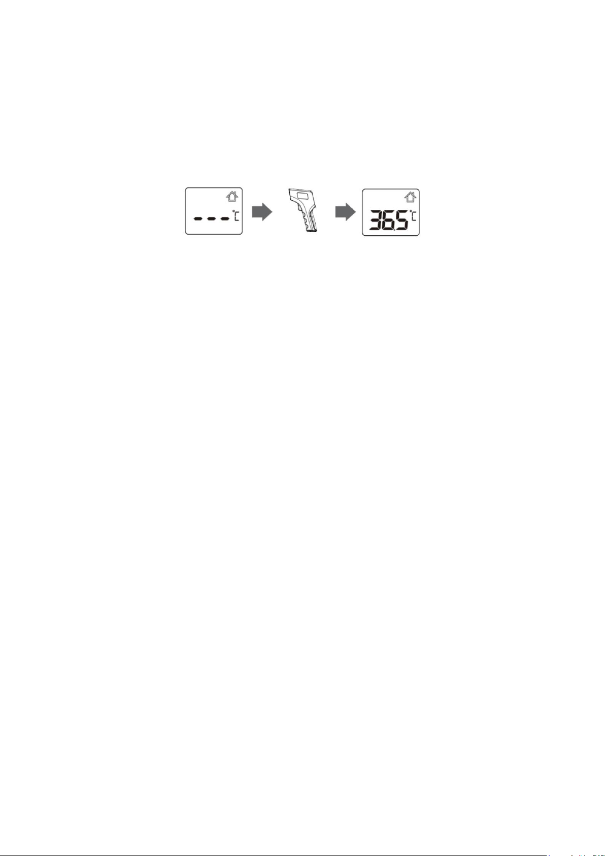
Operation: As a Body Thermometer
1. Press the ON/OFF button.
2. When the preparation screen displays (see below) the device is ready for
temperature measurement.
3. Align the device with the centre of the forehead, ensuring the distance between the
forehead and the device is 10mm.
4. Press the ON/OFF button to take temperature. The temperature will appear on the
display, accompanied by one long beep.
•If the reading is between 37.5°C(99.5°F) and 43°C(109.4°F), the display will be accompanied
by ten short beeps.
•As forehead temperature measurement could be affected by sweat, oil and the ambient
temperature of the location, the reading should be taken as a reference only.
•If the probe is placed at an angle close to the forehead, the reading will be affected by
surrounding temperature.
•Babies' skin reacts very quickly to ambient temperature. Therefore, do not take their
temperature during/after breastfeeding as the skin temperature may be lower than their
internal body temperature.
Operation: As an Object Thermometer
1. Press the ON/OFF button.
2. Ensure the device is in Object Mode (see Page 7)
3. Point the device at the object to be measured.
4. Press the ON/OFF button to take temperature. The temperature will appear on the
display, accompanied by one beep.
•As forehead temperature measurement could be affected by sweat, oil and the ambient
temperature of the location, the reading should be taken as a reference only.
•If the probe is placed at an angle close to the object, the reading will be affected by
surrounding temperature.
10
Operation: As an Ambient Thermometer
1. Press the ON/OFF button.
2. Ensure the device is in Ambient Temperature Mode (see Page 7)
3. Press the ON/OFF button to take temperature. The temperature will appear on the
display, accompanied by one beep.
Memory Recall of Measurements
1. With the device switched off, press the MEMORY button to enter Read Memory
Mode.
2. The ‘M’ icon and the first recorded memory appears.
3. Press the MEMORY button to move through the saved measurements.
Clear Measurements Memory
1. With the device switched off, long press the MEMORY button for eight seconds.
2. The display will show ‘CLr’
3. Press the ON/OFF button to confirm. ‘CLr’ will flash three times, accompanied by
beeps, and the memory will be cleared.

11
Error Messages
Symbol
Explanation
In Body Mode, measured temperature is above the measuring
range of 43 ℃/109.4℉.
In Body Mode, measured temperature is below the measuring
range of 32℃/89.6℉.
In Object Mode, measured temperature is above the measuring
range 100.0℃/199.9℉,or environmental temperature is above
the measuring range of 40℃/104.0℉.
In Object Mode, measured temperature is below the measuring
range of 0.0℃/32.0℉, or environmental temperature is below the
measuring range of 5℃/41.0℉.
In Ambient Mode, measured temperature is above the
measuring range of
40.0°C/104.0°F.
In Ambient Mode, measured temperature is below the
measuring range of 0.0°C/32.0°F.
Low battery, replace the batteries.
Err
Device has failed or is affected by electric magnetic field.

12
Warranty
•The device is guaranteed to be free of defects in workmanship and materials
under normal use for a period of 1 Year from the date of purchase.
•For repair under this warranty, our authorised service agent must be advised
of the fault within the period of the warranty. This warranty only covers parts
and labour service under normal operations. Any defect resulting from natural
causes, eg.flood, hurricane etc, is not covered in this guarantee. This
guarantee does not cover damage incurred by use of the unit not in
accordance with the instructions, accidental damage, or being tampered or
serviced by unauthorised service agents.
•The following will be excluded from this warranty: If the thermometer has been
misused, abused, or there has been neglect in following the manual's
instructions on purpose and unauthorised repair or modifications.
•The device requires no calibration.
•The device is not repairable and contains no user serviceable parts.

13
EMC Declaration
Table 1
Guidance and manufacturer's declaration-electromagnetic emissions
The Infrared forehead thermometer is intended for use in the
electromagnetic environment specified below. The customer or the user of
the infrared forehead thermometer should assure that it is used in such an
environment
Emissions
test
Compliance
Electromagnetic
environment-guidance
RF emissions
CISPR 11
Group 1
The Infrared forehead thermometer uses
RF energy only for its internal function.
Therefore, its RF emissions are very low
and are not likely to cause any
interference in nearby electronic
equipment
RF emissions
CISPR 11
Class 「B」
The Infrared forehead thermometer is
suitable for use in all establishments
other than domestic and those directly
connected to the public low-voltage
power supply network that supplies
buildings used for domestic purposes.
Harmonic
Emissions
IEC 61000-3-
2
Class A
Voltage
fluctuations/
Flicker
emissions
IEC 61000-3-
3
Complies
Table 2
Guidance and manufacturer's declaration-electromagnetic emissions
The Infrared forehead thermometer is intended for use in the electromagnetic
environment specified below. The customer or the user of the infrared forehead
thermometer should assure that it is used in such an environment
Immunity
Test
IEC 60601 Test level
Compliance
level
Electromagnetic
Environment-guidance
Electromagne
tic
Discharge
(ESD)
IEC 61000-4-
±8 kV contact
±15 kV air
±8 kV contact
±15 kV air
Floors should be wood,
concrete or ceramic tile. If
floors are covered with
synthetic material, the
relative humidity should be

14
2
at least 30%
Electrical fast
transient/burs
t IEC 61000-
4-4
Power supply
lines:±2 kV
Input/output
Lines:±1 kV
Power supply
Lines:±2 kV
Input/output
Lines:±1 kV
Mains power quality
Should be that of a typical
commercial or hospital
environment.
Surge
IEC 61000-4-
5
line(s) to line(s):±1 kV
line(s) to earth:±2 kV
100 kHz repetition
frequency
line(s) to
line(s) :±1 kV.
line(s) to earth:±2
kV.
100 kHz repetition
frequency
Mains power quality
Should be that of a typical
commercial or hospital
environment.
Voltage
dips,short
interruptions
and voltage
variations on
power supply
inputlinesIEC
61000-4-11
0% 0.5 cycle At
0°,45°,90°,135°,180°,
225°,270° and 315°
0% 1 cycle And 70%
25/30 cycles Single
phase: at 0
0% 300 cycle
0% 0.5 cycle At
0°,45°,90°,135°,1
80°,225°,270°
and 315°
0% 1 cycle And
70% 25/30 cycles
Single phase: at 0
0% 300 cycle
Mains power quality
Should be that of a typical
commercial or hospital
environment.
Power
frequency
(50/60Hz)
magnetic field
IEC 61000-4-
8
30 A/m
50Hz/60Hz
30 A/m
50Hz/60Hz
Power frequency magnetic
fields should be at levels
characteristic of a typical
commercial or hospital
environment.
NOTE U is the a.c. mains voltage prior to application of the test level.
Table 3
Guidance and manufacturer's declaration-electromagnetic emissions
The Infrared forehead thermometer is intended for use in the electromagnetic environment specified
below. The customer or the user of the Infrared forehead thermometer should assure that it is used in
such an environment
Immunity Test
IEC 60601
Test level
Compliance
level
Electromagnetic environment-guidance

15
Conduced RF
IEC61000-4-6
150KHz to
80MHz:
6Vrms (in
ISM and
amateur
radio
bands)
80% Arm at
1kHz
150KHz to
80MHz:
3Vrms
6Vrms(in
ISM and
amateur
radio
bands)
80% Arm at
1kHz
Portable and mobile RF communications
equipment should be
used no closer to any part of the
Infrared forehead thermometer,
including cables, than the
recommended separation distance
calculated from the equation
appropriate for the frequency of the
transmitter. Recommended separation
distances:
d=0.35;
d=1.2;
Radiated RF
IEC61000-4-3
10V/m,80%
Am at 1kHz
10V/m,80%
Am at 1kHz
80MHz to 800MHz:
d=1.2
800MHz to
2.7GHz:
d=2.3
Where, P is the maximum
output power rating of the
transmitter in watts (W)
according to the
transmitter
manufacturer, d is the
recommended separation
distance in meters (m)
Field
strengths from fixed RF
transmitters, as
determined
by an electromagnetic
site
survey, should be less
than
the compliance level in
each
frequency range.
Interference may occur in
the
vicinity of equipment
marked
with the following
symbol:
NOTE 1 At 80 MHz and 800 MHz, the higher frequency range applies.
NOTE 2 These guidelines may not apply in all situations. Electromagnetic propagation is affected by
absorption and reflection from structures, objects and people.
Field strengths from fixed transmitters, such as base stations for radio (cellular/cordless) telephones
and land mobile radios, amateur radio, AM and FM radio broadcast and TV broadcast cannot be
predicted theoretically with accuracy. To assess the electromagnetic environment due to fixed RF
transmitters, an electromagnetic site survey should be considered. Ifthe measured field strengthin the
location in which the Infrared forehead thermometer is used exceeds the applicable RF
compliance level above, the Infrared forehead thermometer should be observed to verify normal
16
operation. If abnormal performance is observed, additional measures may be necessary, such as re-
orienting or relocating the Infrared forehead
thermometer.
Over the frequency range 150 kHz to 80 MHz, field strengths should be less than 3 V/m.
Table 4
Recommended separation distances between portable and mobile RF communications equipment and
the
The Infrared forehead thermometer is intended for use in an electromagnetic environment in which
radiated RF disturbances are controlled. The customer or the user of the Infrared forehead thermometer
can help prevent electromagnetic interference by maintaining a minimum distance between portable and
mobile RF communications equipment (transmitters) and the Infrared forehead thermometer as
recommended below, according to the maximum output power of the communications equipment.
Rated maximum output
power of transmitter
Separation distance according to frequency of transmitter
150 kHz to 80
MHz
d=3.5
80MHz to
800MHz
d=1.2
800MHz to 2.7GHz
D=2.3
0,01
/
0.12
0.23
0,1
/
0.38
0.73
1
/
1.2
2.3
10
/
3.8
7.3
100
/
12
23
For transmitters rated at a maximum output power not listed above, the recommended separation
distance d in meters (m) can be estimated using the equation applicable to the frequency of the
transmitter, where P is the maximum output power rating of the transmitter in watts (W) according to
the transmitter manufacturer.
NOTE 1 At 80 MHz and 800 MHz, the separation distance for the higher frequency
range applies.
NOTE 2 These guidelines may not apply in all situations. Electromagnetic propagation is affected by
absorption and reflection from structures, objects and people.
Table 5
Guidance and manufacturer's declaration-electromagnetic emissions
The Infrared forehead thermometer is intended for use in the electromagnetic environment specified
below. The customer or the user of the infrared forehead thermometer should assure that it is used in
such an environment
Radiated RF
IEC61000-4-3
(Test
Test
Frequency
(MHz)
Band
a)
(MHz)
Service
a)
Modu
lation
b)
Modulati
on b)(W)
Distanc
e (m)
IMMUNITY
TEST LEVEL
(V/m)

17
specifications
for
ENCLOSURE
PORT
IMMUNITY to
RF wireless
communication
s
equipment)
385
380-
390
TETRA
400
Pulse
modu
lation
b)
18 Hz
1,8
0,3
27
450
380-
390
GMRS
460,
FRS 460
FM c)
±5
kHz
deviat
ion
1 kHz
sine
2
0,3
28
710
704-
787
LTE
Band
13,17
Pulse
modu
lation
b)
217
Hz
0,2
0,3
9
745
780
810
800-
960
GSM
800/900,
TETRA
800,
IDEN
820,
CDMA
850,
LTE
Band
1,3,4,2
5;UMT
S
Pulse
modu
lation
b)
18 Hz
2
0,3
28
870
930
1720
1700-
1900
GSM
1800;
CDMA
1900;
GSM
1900;
DECT;
LTE
Band
1,3,4,25;
UMTS
Pulse
modu
lation
b)
217
Hz
2
0,3
28
1845
1970
2450
2400-
2570
Bluetooth
,
WLAN,
802.11
b/g/n,
RFID
2450,
LTE
Pulse
modu
lation
b)
217
Hz
2
0,3
28

18
Band 7
5240
5100-
5800
WLAN
802.11
a/n
Pulse
modu
lation
b)
217
Hz
0,2
0,3
9
5240
5785
NOTE If necessary to achieve the IMMUNITY TEST LEVEL, the distance between the transmitting antenna
and the
ME EQUIPMENT or ME SYSTEM may be reduced to 1 m. The 1 m test distance is permitted by IEC
6100-4-3.
a) For some services, only the uplink frequencies are included.
b) The carrier shall be modulated using a 50 % duty cycle square wave signal.
c) As an alternative to FM modulation, 50 % pulse modulation at 18 Hz may be used because while it
does not
represent actual modulation. it would be worst case.
The MANUFACTURER should consider reducing the minimum separation distance, based on RISK
MANAGEMENT, and using higher IMMUNITY TEST LEVELS that are appropriate for the reduced
minimum separation distance. Minimum separation distances for higher IMMUNITY TEST LEVELS shall
be calculated using the following equation: E=6/d√P
Where P is the maximum power in W, d is the minimum separation distance in m, and E is the IMMUNITY
TEST LEVEL in V/m.

19

20
+44 (0) 1709 364296
sales@marsdengroup.co.uk
Distribution:
Unit 7, Centurion Business Park,
Coggin Mill Way,
Rotherham,
S60 1FB
Head Office:
Unit 1, Genesis Business Park,
Sheffield Road,
Rotherham
S60 1DX
www.marsden-weighing.co.uk
Other manuals for UFR103
1
Table of contents
Other marsden Thermometer manuals


