Form #906 Rev A
ATTENTION:
The installation of these devices must be in accordance with NFPA standards No. 54 & 58, along with all
federal, state, and local codes. All personnel installing these devices should be trained on the hazards
associated with combustible gases and fluids. MEC assumes no responsibility from damage, injury, or death
that may result from servicing, altering, or the improper installation of this regulator.
OPERATION:
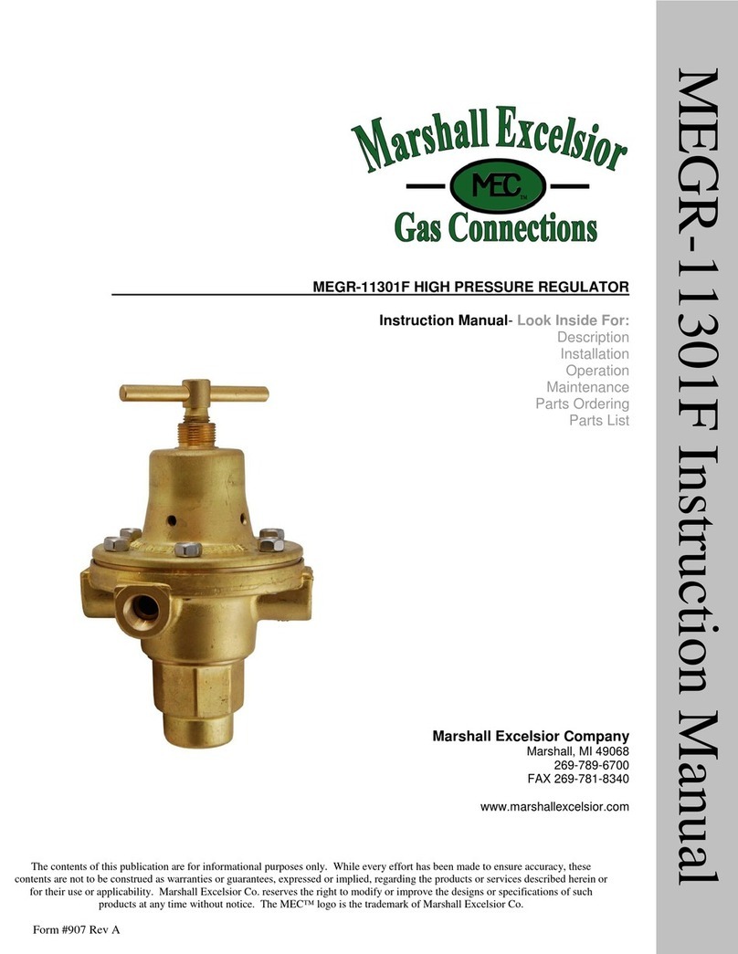
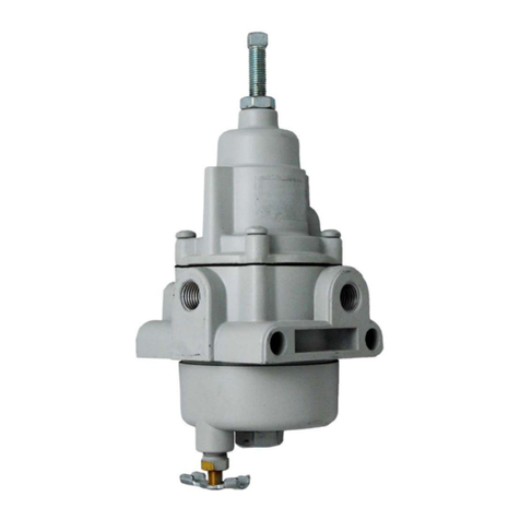
The MEGR-167CH/CW & MEGR-167CN are high pressure (pounds to pounds), industrial gas regulators.
They are designed to conform to UL Standard 144 for use with gas. The maximum supply pressure is 250
PSIG. The maximum output pressure is printed on the regulator nameplate. These regulators are not intended
for use in low-pressure applications below 3 PSIG. Operating temperature ranges are between 0° and 160° F.
The MEGR-167CH/CW regulators are field adjustable with a 5/16" wrench. The MEGR-167CN is factory
preset and is not intended for field adjustment. This preset pressure is printed on the regulator nameplate.
NOTE: It is strongly recommended that a pressure measuring device be installed on the outlet of the
regulator during adjustment to ensure that the regulator is not adjusted beyond the output pressure
range listed on the regulator nameplate. The regulator should not be used to regulate pressure above
what is recommended.
INSTALLATION:
Ensure all gas lines are free from dirt and scale before installation is made. Shut off the gas. The gas
regulator can be mounted at any angle without affecting operation. The inlet and outlet ports for all of these
gas regulators are 1/4" NPT.
Install the regulator as close as possible to the system that it is to supply. Avoid using undersized fittings that
will limit the flow through the regulator and cause downstream pressure drop. Apply a minimum amount of
pipe compound to the male threads of the inlet and outlet piping. The words "IN" and "OUT" are cast into the
body of the regulator to indicate the direction of flow. The regulator must be oriented in the correct flow
direction. Internal damage to the regulator may result from the regulator being installed backwards. The 1/4"
NPT gauge port can also be used as an optional output port, but with decreased flow delivery.
Before putting the MEGR-167CH/CW regulators into service for the first time, relieve compression on the
range spring by turning the adjustment assembly counter clockwise. (Since the MEGR-167CN is preset at
the factory it cannot be adjusted in the field.) It is recommended that the gas supply be introduced slowly to
the regulator. After gas is applied to the regulator, check installation to ensure that there is a bubble tight seal.
This can be accomplished by using a leak detector or applying a small amount of soapy water at the
connection points. To operate, turn the adjustment assembly slowly in a clockwise direction until the required
downstream pressure is obtained. Turned in this direction, the range spring is compressed thus causing
increased output pressure.
CAUTION: These gas regulators are non-relieving regulators and thus cannot exhaust excess pressure
at the regulator. Use of a relief device upstream or downstream of these regulators is recommended in
accordance with NFPA 58. In order to establish an accurate output pressure from the regulator, it will
be necessary to cycle downstream flow or to set the regulator at a slight flow.
