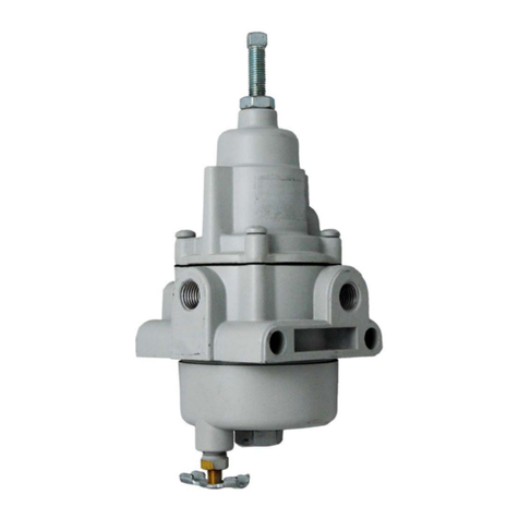
Marshall Excelsior MEGR-1630 User manual

MEGR-1630 HIGH FLOW GAS REGULATOR
Instruction Manual- Look Inside For:
Description
Installation
Overpressure Protection
Startup and Adjustment
Shutdown
Maintenance
Parts Ordering
Parts List
Marshall Excelsior Company
Marshall, MI 49068
269-789-6700
FAX 269-781-8340
www.marshallexcelsior.com
The contents of this publication are for informational purposes only. While every effort has been made to ensure accuracy, these contents
are not to be construed as warranties or guarantees, expressed or implied, regarding the products or services described herein or for their use
or applicability. Marshall Excelsior Co. reserves the right to modify or improve the designs or specifications of such products at any time
without notice. The MEC™ logo is the trademark of Marshall Excelsior Co.
Form #909 Rev B
MEG
R-1630 I
ns
truction
M
anual

Form #909 Rev B
DESCRIPTION:
MEGR-1630 is a spring loaded, self-operated pressure regulator for use with inlet pressures as high as
1500 PSIG and outlet pressures between 3 and 500 PSIG.
INSTALLATION:
Qualified personnel only should perform installation, operation and maintenance in accordance with
NFPA 54 & 58 and other local, State and Federal Regulations.
WARNING!
Over-pressurizing the regulator or any of its adjacent piping could cause equipment damage,
property damage, or personal injury as a result of the bursting of any of the pressure containing
parts. It is highly recommended that a pressure limiting device (usually required by an appropriate
code, regulation, or standard) be installed to prevent operating conditions from exceeding any
limits.
WARNING: These products contain a chemical known to the state of California to cause
cancer and birth defects or reproductive harm.
The regulator can be mounted in any position. An arrow on the bonnet, above the nameplate, indicates the
proper direction of the flow. Inspect the piping and the regulator for any contaminants before installing.
Always apply pipe sealant to the male threads of the piping.
OVERPRESSURE PROTECTION:
The MEGR-1630 pressure regulator has rated outlet pressures that are lower than their rated inlet
pressures. Pressure relief devices must be used if either the inlet or outlet pressure can exceed their rated
limit. See the tables and notes below for those limits. After any overpressure condition, check the regulator
and any piping for damage.
WARNING!
The use of a pressure-relieving device is recommended to ensure that both the inlet and outlet
pressures do not exceed their rated limits. Damage to the regulator, or personal injury, could result
from an overpressure condition.
Orifice Size
Maximum Inlet
Pressure (psig)
Maximum
Pressure
Differential (psi)
1/8" and 3/16"
1500
1500
1/4"
1500
1000
3/8"
1000
500
1/2"
750
250
Outlet Pressure
Range (psig)
Maximum Outlet Pressure (psig)
Above the Pressure Setting
Maximum Emergency
Outlet Pressure (psig)
27-50
200
550
46-95
200
550
90-150
200
550
200-275
200
550
275-500
200*
550

Form #909 Rev B
NOTE: The sum of the outlet pressure and the maximum pressure differential must be greater than the inlet
pressure.
CAUTION: The maximum outlet emergency pressure (casing pressure) is 550 psig. This number takes
precedence over the maximum outlet pressure above the pressure setting.
VENTS:
The MEGR-1630 pressure regulator is supplied with a screened vent assembly in the 1/4 NPT bonnet vent
hole.
WARNING!
The vent should be inspected periodically to insure that it has not become plugged. Make sure the
vent remains free from any foreign debris, or weather related contaminants. If the regulator is to be
used in an enclosed area, vent lines should be piped to a ventilated area.
START UP:
To start up the regulator, open the upstream shut-off valve allowing gas pressure to enter. The use of
gauges to monitor pressures is strongly advised. The outlet pressure range is noted on the nameplate. In
the event that the desired pressure setting is outside the rated pressure range of the regulator, substitute
the correct range spring. Make sure the nameplate is changed to reflect the new outlet pressure range.
WARNING!
To prevent placing the range spring under excessive stress, always use the correct adjustment
screw for the range selected.
Dangerous conditions, which may damage internal components, may result from outlet pressures
exceeding the set pressure by more than 200 psig. This excess pressure must never exceed the maximum
casing pressure of 550 psig. To prevent overpressure conditions, make certain the new pressure setting
does not exceed the limits of the range spring being used. The use of a pressure gauge when making
adjustments is strongly recommended.
SHUTDOWN:
Slowly close the upstream shut-off valve and relieve the system of all pressure. The use of pressure
gauges is recommended to ensure that there is no upstream or downstream pressure still applied to the
regulator or pressure system.
MAINTENANCE:
During the course of the regulator's service it may become necessary to replace or repair certain
components.
WARNING!
These procedures are for gaining access to the range spring, diaphragm assembly, and the lever.
All spring pressure must be released from the regulator before these steps can be performed. While

Form #909 Rev B
following these procedures, refer to the diagram for item number locations unless otherwise
directed. Assembly is the reverse of these procedures.
Replacing the Orifice, Valve Disk Assembly and Lever
1. Disconnect the piping from the inlet housing (item19)
2. Remove 4 screws (item 18) and thehousing
3. Remove the orifice (item 22), and the 2 gaskets (item21)
4. If necessary, disconnect the remote ventpipe
5. Remove the 2 screws that attach the diaphragm housing (item 14) to the inlet body (item 20) and
separate
6. Remove the pin (item 16) and slide out the lever (item 15). When replacing the lever, make sure the
slot in the lever contacts the connector (item13).
7. Remove the carrier assembly (item 24) from the inletbody.
8. Using a 3/4" socket wrench, remove the valve disk and holder assembly (item23).
9. Replace those parts that show wear, andreassemble.
Note: New gaskets (item 17 and 21) should always be installed when rebuilding a MEGR-1630 Regulator.
Replacing the Diaphragm
1. Loosen locknut (item 4) and turn adjustment screw (item 3) counterclockwise until allspring
compression is removed.
2. If necessary, disconnect the remote ventpipe.
3. To remove the bonnet (item 6), unscrew the nuts (item 11) and remove the bolts (item 12).
NOTE: Nuts will not be present on units with steelenclosures.
4. Separate the diaphragm assembly (items 8,9, 10 and 13) from the lever (item 15) andremove.
5. Unscrew the screw (item 8) from the connector assembly (item13).
6. Install the new diaphragm, being certain that it is centered, andreassemble.
NOTE: Be careful not to twist the diaphragm/lever attachment during assembly. When installing the
bonnet, install the screws finger tight, turn the adjusting screw clockwise to slightly compress the
spring and take up any slack in the diaphragm, then finish tightening the screws and nuts.
Table 1
Spring
Range
(psig)
Adjusting
Screw
Spring Color
Code
27-50
Specify Spring
Range when
Ordering
Red Stripe
46-95
Olive Drab
90-150
Silver
150-200
Green Stripe
200-275
Blue Stripe
275-500
Yellow Stripe

Form #909 Rev B
PARTS LIST
ITEM
DESCRIPTION
1
Nameplate
2
Drive Screws (4 Req'd)
3
Adjusting Screw (See Table 1)
4
Hex Nut
5
Upper Spring Guide (0-275 psig Pressure Range)
Upper Spring Guide (over 275 psig Pressure Range)
6
Bonnet - Iron
7
Spring (See Table #1)
8
Screw
9
Lower Spring Guide (0-275 psig Pressure Range)
Lower Spring Guide (over 275 psig Pressure Range)
10
Diaphragm - Neoprene
11
Hex Nut (4 Req'd)
12
Build Screw (4 Req'd)
13
Connector Piston Assembly - Aluminum Trim
14
Diaphragm Housing - Iron
15
Lever Assembly
16
Pin
17
Gasket
18
Build Screw (4 Req'd) 2" Body
19
Inlet Adapter - 2" NPT Iron
20
Body - 2" NPT Iron
21
Body Gaskets (2 Req'd)
22
Orifice - 1/8"
Orifice - 3/16"
Orifice - 1/4"
Orifice - 3/8"
Orifice - 1/2"
23
Valve Disk Assembly - NBR
24
Valve Carrier
26
Vent Protector Assembly
27
Cap Screws (Body to Housing)

SIDE VIEW
Table of contents
Other Marshall Excelsior Controllers manuals

Marshall Excelsior
Marshall Excelsior MEGR-253 User manual

Marshall Excelsior
Marshall Excelsior MEGR-167CH/751 User manual

Marshall Excelsior
Marshall Excelsior MEGR-253 Series User manual

Marshall Excelsior
Marshall Excelsior MEGR-11301F User manual

Marshall Excelsior
Marshall Excelsior MEC MEGR-167CH User manual

Marshall Excelsior
Marshall Excelsior MEGR-1627 User manual