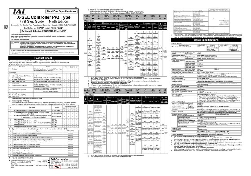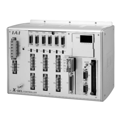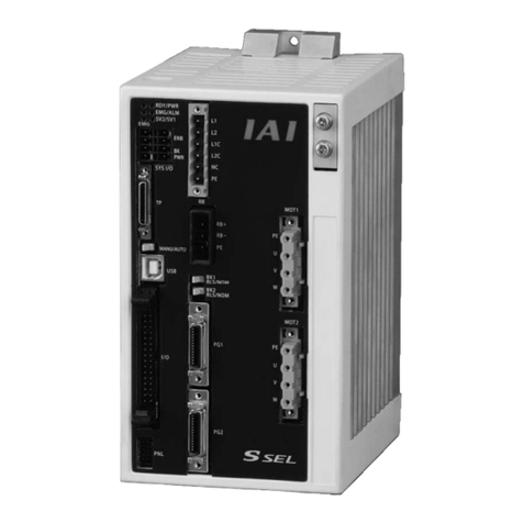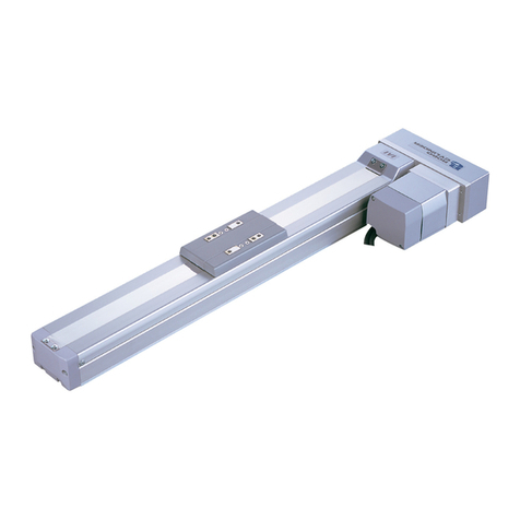
Specification Item XSEL-RA/RAX/RAXD XSEL-SA/SAX/SAXD
Motor Control System AC full-digital servo
Applicable Encoder
Battery-less absolute encoder, incremental serial encoder or absolute serial encoder
Speed Setting From 1mm/s The upper limit depends on the specifications of actuator
Acceleration Setting From 0.01G The upper limit depends on the specifications of actuator
Serial
Communication
Interface
Teachin
por
Connector dedicated for teachin
tool Connecto
: D-sub 25 pin
USB port Applicable for USB2.0
Connecto
: Mini-B
EtherNet 10/100/1000BASE-T
Connecto
: RJ-45
RS232C
Port 1
RS232C: 1CH
Baud rate: Max. 230.4kbps Connector: D-sub 9 pin
Cable len
th: Max.10m
External
Interface
PIO Type
PIO Board MAX. 2 pieces
Signal I/O dedicated for 24V DC (Input and output ports, selected from
NPN/PNP
[Refer to How to read the model of the controller]
Field Network Type
DeviceNet, CC-Link, PROFIBUS-DP, EtherNet/IP, EtherCAT
(For either of DeviceNet, CC-Link or PROFIBUS-DP and either of EtherNet/IP
or EtherCAT, either of the boards can be inserted at the same time.)
[Refer to each Fieldbus Instruction Manual]
Data Setting and Input PC software,
touch panel teachin
pendant TB-01/01D/01DR, TB-02/02D o
TB-03
Program Specification SEL language
Max. Number of Program Steps 20000 steps
Max. Number of Positions
1-axis t
pe : 60000 position 5-axis t
pe : 33333 position
2-axis t
pe : 50000 position 6-axis t
pe : 30000 position
3-axis t
pe : 42867 position 7-axis t
pe : 27272 position
4-axis t
pe : 37500 position 8-axis t
pe : 25000 position
Max. Number of Programs 255 programs
Max. Number of Multitask Programs 16 programs
Data Retention Memory Flash ROM + FRAM
Extension Motion Control Master Feature ROBO Cylinder Controllers of MECHATROLINK-Ⅲ type max. 32 axes
Clock Function
Retaining time after power turned off: approximately 10 days
Time for battery charge after power is on after the clock data is lost:
approximately 100 hours
System I/O Emergency stop input, safety gate input, system ready output and other safety
circuit inputs and outputs, and MANU/AUTO external chan
eove
Safety Circuit
Configuration
Drive-source Cutoff Method Internal Relay External Safety Circuit
Emergency-Stop Input
b Contact (Normally Closed)
Input (internal power supply)
b Contact (Normally Closed) Input
(external power supply, duplication
available
Enable Input
b Contact (Normally Closed)
Input (internal power supply)
b Contact (Normally Closed) Input
(external power supply, duplication
available
System Ready Output No-voltage contact (relay) output Max.200mA (DC24V)
Protective Functions
Motor over current, overload, motor driver temperature check, overload check,
encoder open circuit detection, soft limit over, system abnormality, battery
abnormality
Regenerative Resistor Equipped with built-in 1kΩ/20W regenerative resistor
Extension available with connecting an external regenerative resistor
Absolute Batter
AB-5
Enclosed in Product
Mounted inside robot for SCARA Robot.
Protection Function against Electric Shock Class 1 In case grounding conducted on ground terminal in addition to basic
insulation for electric shock proof.
Overvoltage Category Category 2 Voltage durability 2500V at less than 300V AC for input rating
Insulation Resistance 10MΩ or more (Between power terminal and I/O terminal and also all external
terminals and case at the power supply of DC500V)
Insulation strength 1500V AC for 1 min.
Cooling Method Forced Air-Cooling
Environment
Surrounding air temperature 0 to +40°C
Surrounding humidity 85% RH or less (non-condensing)
Surrounding environment [Refer to the Item for the Installation Environment]
Surrounding storage
temperature -20 to 70°C (The Absolute Battery is excluded.)
Surrounding storage humidity 85% RH or less (non-condensing)
Maximum Operation Height 1000m
Vibration Resistance
10 to 57Hz in XYZ directions/Pulsating amplitude 0.035mm (continuous),
0.075mm (intermittent) 57 to 150Hz/4.9m/s² (continuous),
9.8m/s² (intermittent)
Protection Class IP20
Pollution Degree Pollution Degree 2
External Dimensions [Refer to the External dimensions Dimension]
Mass
Four-axis
type frame
Without absolute
batter
uni
Approx. 4.4kg 3-phase type: Approx. 3.8kg Single-phase type: Approx. 4.4kg
With the absolute
batter
uni
Approx. 5.0kg 3-phase type: Approx. 4.4kg Single-phase type: Approx. 5.0kg
XSEL-SAX4-NNN10040/12040: Approx. 5.3k
Eight-axis
type frame
Without absolute
batter
uni
Approx. 5.3kg 3-phase type: Approx. 4.7kg Single-phase type: Approx. 5.3kg
With the absolute
batter
uni
Approx. 6.0kg 3-phase type: Approx. 5.4kg Single-phase type: Approx. 6.0kg
Note 1 Rush current at the power connection continues for 3 msec. Note that the value of in-rush current differs
depending on the impedance of the power supply line.
Note 2 Leak current varies depending on the capacity of connected motor, cable length and the surrounding
environment. Measure the leak current at the point where a ground fault circuit interrupter is to be
installed when leakage protection is conducted.
Regarding the leakage breaker, it is necessary to have a clear purpose for selection such as a fire
protection or protection of human body. Use the harmonic type (for inverter) for a leakage breaker.
Note 3 Power supply is not necessary if PIO is not to be used.
[Power Capacity and Heating Value]
Rated Power Capacity [VA] = Total Capacity of Motor Power [VA] + Total of the power consumption at the control part
[VA]
Heating Value [W] = Total Output Loss [W] + (Total of internal power consumption [VA] × 0.7 (Efficiency) × 0.6 (Power
factor))
• Select the Motor Driving Power [VA] from the Table 1 and 2.
• Figure out the total of the power consumption at the control part [VA] with the total of power of the actually
mounted components • quantity, by selecting the applicable ones from Table 3 Control Power Source (Internal
Consumption and External Consumption).
• To calculate the sum total of output loss [W], refer to the “Output Loss” column in Table 1 below and select the
values corresponding to the output losses of each connected actuator.
• For the inner power demand (VA) for calculating the heating value (W) in the control unit, select the components
which are being placed, from the columns of Control Power Supply (Internal Consumption) and External Power
Supply (Internal Consumption) in Table 3 and calculate it using the formula “Power • Quantity of the Placement
Component”
Table: 1 Motor Power Capacity of Single-Axis Actuator and Output Loss
Wattage of Actuator
Motor [W]
Motor Power
Capacity [VA]
Output loss = Heat
Generation [W]
Wattage of
Actuator Motor [W]
Motor Power
Capacity [VA]
Output loss = Heat
Generation [W]
20 26 1.58 100 (Linear Actuator
LSAS-N10SS) 379 4.48
30 46 2.07
60 138 3.39 200 (Linear Actuator
LSAS-N15SS) 486 4.37
100 234 6.12
150 328 8.30 200 (Linear Actuator
LSAS-N15HS) 773 6.42
200 421 9.12
400 796 19.76 DD/DDA (200W) 503 7.5
600 1164 27.20 DD/DDA (600W) 1462 20.8
750 1521 29.77 RCS3-CTZ5C (60W) (Note 1) 197 3.6
RCS3-CT8C (400W) (Note 1) 1230 18.0
Note 1 Assume 120W for RCS3-CTZ5C and 800W for RCS3-CT8C when performing calculation for those such as the power capacity.
Table: 2 Motor Volt Amperage of SCARA Robot and Output Loss Note 1 Calculated with 0.6 for power factor
SCARA Robot Wattage [W]
(Rated output)
Motor Power Capacity
[VA] (Note 1)
Output loss =
Heat Generation [W]
IX-NN1205/1505/1805 129.8 216.3 8.13
IX-NN2515H/3515H, IX-TNN(UNN)3015H/3515H 1117.9 1863.1 44.8
IX-NN50H/60H, IX-HNN(INN)5020H/6020H 2218.0 3696.7 69.7
IX-NN70H/80H, IX-HNN(INN)7020H/8020H 3880.6 6467.7 93.2
IX-NSN5016H/6016H 4102.9 6338.1 95.2
IX-NNN10040/12040 6412.6 10687.7 131.6
IXA-3NNN1805 319.4 532.3 10.7
IXA-3NNN3015 1330.4 2217.3 34.0
IXA-3NNN45 1178.8 1964.7 33.3
IXA-3NNN60 1469.1 2448.5 43.6
IXA-4NNN1805 356.0 593.4 14.3
IXA-4NNN3015 1582.3 2637.1 40.3
IXA-4NNN45 1370.6 2284.3 38.6
IXA-4NNN60 1660.9 2768.1 48.9
IXA-3NSN3015 2343.0 3905.1 54.0
IXA-3NSN45 2533.6 4222.7 55.3
IXA-3NSN60 2413.5 4022.6 56.3
IXA-4NSN3015 2594.9 4324.8 60.4
IXA-4NSN45 2725.4 4542.3 60.5
IXA-4NSN60 2605.3 4342.2 61.6
IXA-4NSW3015 2555.5 4259.1 61.6
IXA-4NSW45 2399.3 3998.9 60.5
IXA-4NSW60 2496.2 4160.3 61.6
Table: 3 Motor Driving Power and Output Loss
Control power supply External Power Source
(24VDC)
Quantity
Internal
Consumption
[VA]
External
Consumption
[VA]
Internal
Consumption
[VA]
External
Consumption
[VA]
Base Unit 46.64 1
Driver Per Board 6.26
[Refer to Table 4]
Encoder
Section Per axis 2.38 3.57
Fan Unit Per fan 5.71
Axis Sensor Per axis 4.57
I/O Board DIO (48 points) N1, N2
P1, P2 5.95 14.52 0 to 2 Number of PCBs
on I/O slot 1 and
2
DIO (96 points) N3, P3 8.33 26.81 0 to 2
Network
Module
DeviceNet DV 1.98 3.43 0 to 1 Number of PCBs
on Field Network
Board 1
CC-Link CC 5.67 0 to 1
PROFIBUS-DP PR 1.98 0 to 1
EtherNET/IP EP 1.98 0 to 1 Number of PCBs
on Field Network
Board 2
EtherCAT EC 3.93 0 to 1
Teaching
pendant TB-01, TB-02, TB-03 8.57 0 to 1
Brake Per axis 0.12 2.5 7.5 Total number of brake-
equipped actuators 0 to 8
Table: 4 Number of Controlled Parts
Number of axes
1-Axis 2-Axis 3-Axis 4-Axis 5-Axis 6-Axis 7-Axis 8-Axis
Driver 1 1 2 2 3 3 4 4
Encoder Section 1 2 3 4 5 6 7 8
Fan Unit
Fou
-axis t
pe frame Ei
ht-axis t
pe frame
XSEL-RA/RAX : 5 units
XSEL-SA/SAX (three phase type) : 4 units
XSEL-SA (single phase type) : 5 units
XSEL-RA/RAX/RAXD : 6 units
XSEL-SA/SAX/SAXD (three phase type) : 5 units
XSEL-SA (single phase type) : 6 units
XSEL-SAX4-NNN10040
12040 : 6 units
Axis Sensor 1 2 3 4 5 6 7 8
[Selection of Circuit Interrupter]
• 3 times of the rated current flows to the controller during the acceleration/deceleration. Select one that does not trip
when the above current passes. When it trips, select the breaker with a rated current one rank above. (Confirm that
Operation Characteristic Curve described in the catalogue of each manufacturer.)
•
For the rated breaking current, select the current value which can break the current even when a short circuit occurs.
Rated Breaking Current > Short-circuit Current = Primary Power Supply Capacity/Power Voltage
• Consider margin for the rated current on the circuit breaker.
Rated current of circuit breaker >
rated voltage amperage [VA] / AC input voltage × Margin (1.2 to 1.4 for reference)
[Selection of Leakage Breaker]
• Regarding the leakage breaker, it is necessary to have a clear purpose for selection such as a fire protection or
protection of human body.
• Leak current varies depending on the capacity of connected motor, cable length and the surrounding environment.
Measure the leak current at the point where a ground fault circuit interrupter is to be installed when leakage
protection is conducted.
• Use the applicable to higher harmonics type leakage breaker.
External Dimensions
1. Absolute Battery Non-Equipped Type
Controller Type
All Types Equipped
Four-axis Type Frame Eight-axis Type Frame
RA
(Single-phase/
3-phase type)
290
304
180
186
195
2512012025
5
3-φ5
358
372
180
186
195
5912012059
5
3-φ5
SA
(Single-phase type)
RAX/RAXD
(3-phase type)
SA/SAX/SAXD
(3-phase type)
247
261
180
186
195
48.5757548.5
5
3-φ5
315
329
180
186
195
57.510010057.5
5
3-φ5
Side View
125.3
(80)
3
125.3
(80)
3
* There is only the eight-axis type frame for XSEL-RAXD/SAXD.
2. Absolute Battery Equipped Type
Controller Type
All Types Equipped
Four-axis Type Frame Eight-axis Type Frame
RA
(Single-phase/
3-phase type)
290
333
180
186
195
2512012025
5
3-φ5
(36)
290
333
180
186
195
2512012025
5
3-φ5
(36)
SA
(Single-phase type)
RAX/RAXD
(3-phase type)
XSEL-SAX4-
NNN10040,
NNN12040
SA/SAX/SAXD
(3-phase type)
315
329
180
186
195
57.510010057.5
5
3-φ5
247
290
180
186
195
48.5757548.5
5
3-φ5
(36)
Side View
125.3
(80)
3
125.3
(80)
3
Standard
(3 places)
Standard
(3 places)
Standard
3
laces
Standard
(3 places)
Standard
(3 places)
Standard
(3 places)
* There is onl
the ei
ht-axis t
pe frame for XSEL-RAXD/SAXD.
Standard
(3 places)
Standard
(3 places)
