manuals.online logo
Brands
  1. Home
  2. •
  3. Brands
  4. •
  5. Marshall Excelsior
  6. •
  7. Industrial Equipment
  8. •
  9. Marshall Excelsior ME990-3F-VRK User manual

Marshall Excelsior ME990-3F-VRK User manual

ME990-3F-VRK
COMPLETE VALVE REPAIR KIT
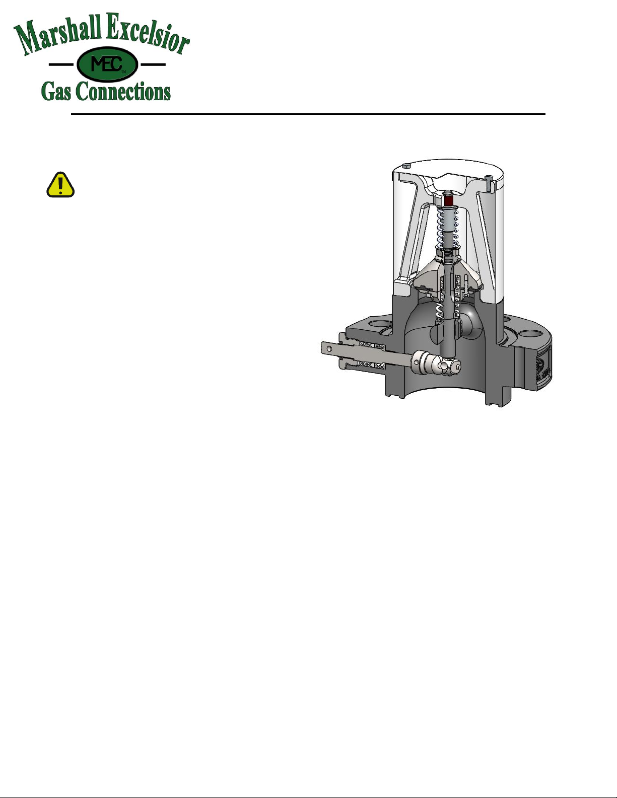
FOR: ME990-3F 3" SINGLE FLANGE
INTERNAL VALVE
Marshall Excelsior Company
1506 George Brown Drive Marshall, MI 49068
Phone (269) 789-6700 Fax (269) 781-8340
www.marshallexcelsior.com
The contents of this publication are for informational purposes only. While every effort has been made to ensure accuracy,
these contents are not to be construed as warranties or guarantees, expressed or implied, regarding the products or services
described herein or for their use or applicability. Marshall Excelsior Co. reserves the right to modify or improve the designs
or specifications of such products at any time without notice. The MEC™ logo is the trademark of Marshall Excelsior Co.
Form #1133 Rev A 3/7/2018
!!!WARNING!!!
READ AND UNDERSTAND ALL INSTRUCTIONS INCLUDED WITH THIS REPAIR KIT
RELIEVE ALL PRESSURE FROM SYSTEM BEFORE REMOVING VALVE FOR SERVICE
NOTE: Numbers in brackets [ ] refer to the number
in the valve component list.
WARNING: These products contain a chemical
known to the state of California to cause cancer and
birth defects or reproductive harm
A. Disassembly
1. EVACUATE ALL PRESSURE FROM
SYSTEM BEFORE ANY DISASSEMBLY
OR REPAIR.
2. Remove (8) Bushings [19] from Valve Body
[1] and discard (not shown).
3. Remove (2) Cap Screws [2] from Screen Cap
[3] and discard.
4. Remove Screen Cap [3] and Screen [4]; retain
components.
5. Remove (4) Cage Screws [5] from Valve
Cage [6] and discard.
6. Remove Valve Cage [6] and Cage Bushing [7]
and discard.
7. Remove Spring Guide [8], Closing Spring [9]
and Spring Washer [10] and discard.
8. Remove Lock Nut [11] and Bleed Disc [12]
and discard.
9. Remove Valve Poppet [13] and discard.
10. Remove Excess Flow Spring [14] and retain.
11. Remove Spring Seat [15] and Stem [16] and
discard.
12. Remove Guide Bearing [17] and discard.
13. Remove Cam Pin [19] and Cam [20] from
Gland Assembly [18] and discard.
14. Remove Gland Assembly [18] and discard.
15. Inspect Valve Body [1] and clean if necessary,
be sure interior is free of dirt, residue and
foreign particles.
B. Reassembly
1. Apply Loctite #242 or equivalent thread
locker to gland threads of Body [1]; install
new Gland Assembly [18]; see recommended
orientation below.
2. Install new Cam [20] and new Cam Pin [19]
onto Gland Assembly [18].
3. Install new Guide Bushing [17] into Body [1]
4. Install new Spring Seat [15], retained Ex-Flow
Spring [14], and new Valve Poppet [13] onto
new Stem [16] in order and orientation shown.
5. Install new Bleed Disc [12] and new Lock Nut
[11] onto Stem [16].
6. Install Stem Assembly [11-16] into Body [1].
ME990-3F-VRK
Form #1133 Rev A 3/7/2018
7. Install new Spring Washer [10] and new
Closing Spring [9] onto Stem [16]
8. Install new Spring Guide [8] onto Stem [16] in
orientation shown.
9. Install new Cage Bearing [7] into new Valve
Cage [6]
10. Apply Loctite #242 or equivalent thread
locker to (4) cage-screw threads of Body [1];
install new Valve Cage [6] onto Body, install
(4) new Cage Screws [5] to retain.
11. Install Screen [4] and Screen Cap [3] onto
Valve Cage [6]; install (2) new Cage Screws
[2] to retain.
12. Connect the valve assembly outlet to a
pressure source of at least 150 PSI. Check for
leaks at all joints and stem seals using a
suitable leak detector solution such as
"Marshall Excelsior" leak detector.
CAUTION: DO NOT USE THE VALVE
IF ANY JOINT CONTINUES TO LEAK
UNDER PRESSURE
C. Component List
Item
no.
Description
Qty
Included
in Kit
1
Body
1
N
2
Cap Screw
2
Y
3
Screen Cap
1
N
4
Screen
1
N
5
Cage Screw
4
Y
6
Valve Cage
1
Y
7
Cage Bushing
1
Y
8
Spring Guide
1
Y
9
Closing Spring
1
Y
10
Spring Washer
1
Y
11
Lock Nut
1
Y
12
Bleed Disc
1
Y
13
Valve Poppet
1
Y
14
Excess Flow Spring
1
N
15
Spring Seat
1
Y
16
Valve Stem
1
Y
17
Guide Bearing
1
Y
18
Gland Assembly
1
Y
19
Cam Pin
1
Y
20
Cam
1
Y
21
Bushings (Not shown)
8
Y
ME990-3F-VRK
Form #1133 Rev A 3/7/2018
Recommended orientation for install

Other Marshall Excelsior Industrial Equipment manuals

Marshall Excelsior MER470 STANDARD KIT User manual

Marshall Excelsior

Marshall Excelsior MER470 STANDARD KIT User manual

Marshall Excelsior Accu-Max+ Series Service manual

Marshall Excelsior

Marshall Excelsior Accu-Max+ Series Service manual

Popular Industrial Equipment manuals by other brands

ABB +Q957 user manual

ABB

ABB +Q957 user manual

G.B.C BASIC EDGE 50 instruction manual

G.B.C

G.B.C BASIC EDGE 50 instruction manual

Tronair Batpak 11-6602-1000 Operation & service manual

Tronair

Tronair Batpak 11-6602-1000 Operation & service manual

Pilz PNOZ mi2p Operation manual

Pilz

Pilz PNOZ mi2p Operation manual

Clemco Zero BNP 6012 manual

Clemco

Clemco Zero BNP 6012 manual

Erskine Attachments V-Plow Operator's manual

Erskine Attachments

Erskine Attachments V-Plow Operator's manual

ABB HT610965 Operation manual

ABB

ABB HT610965 Operation manual

Morra MH 540 user manual

Morra

Morra MH 540 user manual

Eaton S090ST manual

Eaton

Eaton S090ST manual

GRIGGIO G 240 P4 instructions

GRIGGIO

GRIGGIO G 240 P4 instructions

Nexen AIR CHAMP HT45 user manual

Nexen

Nexen AIR CHAMP HT45 user manual

WTE V5 installation manual

WTE

WTE V5 installation manual

ABB HT845232 Operation manual

ABB

ABB HT845232 Operation manual

SMC Networks CJP Series Operation manual

SMC Networks

SMC Networks CJP Series Operation manual

JohnDow Industries JDI-AFT58 Operator's manual

JohnDow Industries

JohnDow Industries JDI-AFT58 Operator's manual

IMB MB9016A instruction manual

IMB

IMB MB9016A instruction manual

Clarke CUMB1 Assembly & operating instructions

Clarke

Clarke CUMB1 Assembly & operating instructions

amiad Arkal Spin Klin 2 user guide

amiad

amiad Arkal Spin Klin 2 user guide

manuals.online logo
manuals.online logoBrands
  • About & Mission
  • Contact us
  • Privacy Policy
  • Terms and Conditions

Copyright 2025 Manuals.Online. All Rights Reserved.