III. Installation
BISTABLE RELAY BR-11 may be installed only by a person authorized to operate electrical installations.
Remember to choose the right protection.
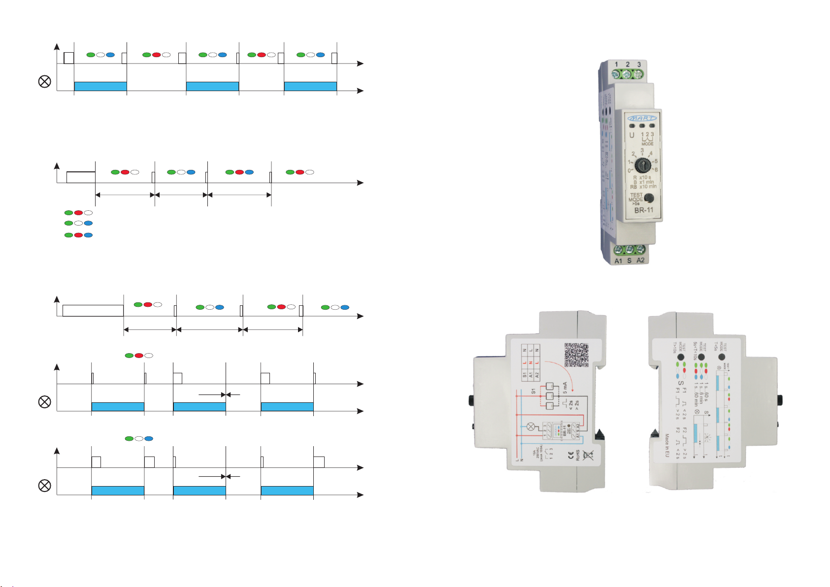
On the front panel of the BR-11 BISTABLE RELAY, there are three informative LEDs: green, red and blue, and
the TEST - MODE button.
On the side walls of the BR-11 BISTABLE RELAY there are: connection diagram and operating characteristics.
In order to connect the BISTABLE RELAY BR-11:
1. make sure the electrical system is turned off
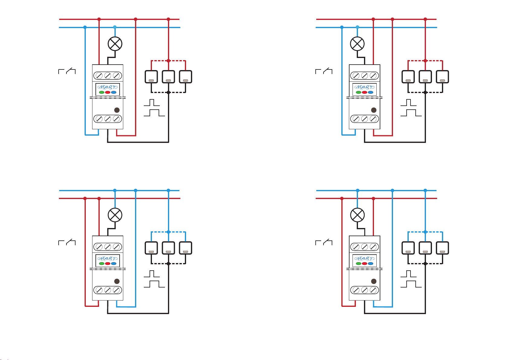
2.connect the BISTABLE RELAY BR-11 according to the diagram (fig.1, fig.2) in the options:
> S1 control signal from L voltage
> S1 control signal from voltage N
> when using terminals 1-2 - after switching on the power, the receivers are turned off
> when using terminals 2-3 - after turning on the power, the receivers are turned on
3.switch on the supply voltage:
> the green LED lights up
> after 1 s they will flash twice - red LED and blue LED
> after 2 seconds, the blue LED will light up, which indicates closed contacts 2-3
4.press the TEST-MODE button (less than 5 s)
> the blue LED turns off and the red LED turns on
> contacts 2-3 will open and contacts 1-2 will close
> subsequent switching on of the TEST-MODE button will change the contact state
5. check operation with impulse switch
> each subsequent switching on causes a change in the voltage status on the receiver and a change in the
LED lighting:
- blue - contacts 2-3 closed
- red - contacts 1-2 closed
6.By using the TEST-MODE button, you can also select:
>> turn-off delay time
> press the TEST-MODE button for more than 5 seconds
> when the LEDs blink (red LED, blue LED) - release the TEST-MODE button
> successive presses of the TEST-MODE button change the ranges:
LED red - range 60 s, LED blue - range 6 min, LED red and LED blue - range 60 min.
After the control range is selected, the potentiometer is active on the selected range
>> how to start the function
> press the TEST-MODE button for more than 10 s
> release the TEST-MODE button - successive presses of the TEST-MODE button change the way
starting the function:
LED red:
> starting function I - with an impulse within the 40 ms ... 2 s interval
> starting function II - with an impulse longer than 2 s
Blue LED:
> starting function I - with an impulse longer than 2 s
> starting function II – with an impulse within the range of 40 ms ... 2 s
After setting each function, wait 10 seconds for the settings to be accepted. After 10 seconds, the red LED and
blue LED will go out for a moment, and the red LED and the blue LED will light up again for a moment. The
LED (red or blue) will light up - the state of the relay before changing the settings.
7. the efficiently operating installation is ready for operation
8. BISTABLE RELAY BR-11 does not respond to impulse when the pause between successive pressings is
shorter than 200 ms.
9. A schematic diagram of the operation of the BISTABLE RELAY BR-11 is shown in Fig. 3.
BISTABLE RELAY BR-11 can work with an unlimited number of switches without illumination and a limited
number of switches with illumination, connected in parallel:
- neon illuminated connectors (1mA) <5 pcs.
Fig.1.An exemplary diagram of the connection of the BISTABLE RELAY BR-11
along with atable of possible connection variants.
IV. Technical data
Rated supply voltage LN
Rated frequency
Maximum load current (power):
> resistive load
> incandescent lamps
> halogen lamps
> fluorescent lamps
> energy-saving lamps and LED
Instantaneous inrush current
Executive contacts
Rated power consumption
Short‑circuit current of impulse buttons
Response time to the impulse button
Function check
Time delay ranges
Times of starting functions I and II
Time to be ready again
Mechanical durability
Protection level
Cross‑section of connection cables
Installation
Work position
Working temperature
Weight
230 VAC, + 10%, - 15%
50 Hz
16 A, AC1 (4 000 W)
10 A (2500 W)
8 A (2000 W)
8 A (2000 W)
8 A (2000 W)
100 A
1 x NO, 1 x NC
0,5 W
5 mA
< 40 ms
TEST-MODE button
60 s, 6 min, 60 min
40 ms < T1 < 2 s, T2 > 2 s or vice versa
> 200 ms
100 000 operations
IP 20
2
0,2÷2,5 mm
One 18 mm field, 35 mm rail
Vertical
-40...+70 °C
80 g
N
L
16A
250VAC
(peak 100A)
23
1
5 mA
S1
N
L
NL
N
L
A2
A1
S1
1 2 3
BR-11
A1 A2
S
TEST
MODE