manuals.online logo
Brands
  1. Home
  2. •
  3. Brands
  4. •
  5. Mart
  6. •
  7. Switch
  8. •
  9. Mart TS-42-4 ECO User manual

Mart TS-42-4 ECO User manual

In order to protect the environment, do not throw away used electrical appliances
and electronics together with municipal waste. Used equipment should be delivered to
collection points for recycling free of charge. Any information on this can be obtained
at sellers, distributors, manufacturer or on the Internet. The product's packaging is made of
ecological materials. The PVC packaging tape will be used while stocks last.
The TS-42-4 TWILIGHT SWITCH meets the requirements of the European Union Directives:
- Directive LVD 2014/35/EU - Low Voltage Directive of 26 February 2014
- Directive EMC 2014/30/EU - Eletromagnetic Compatibility Directive of 26 February 2014
V. Repair and maintenance
All repairs of the TWILIGHT SWITCH TS-42-4 are performed by the manufacturer. The device does not
require any maintenance. When the sensor becomes contaminated, clean it with a clean, damp cloth. The
device does not require any additional maintenance.
VI. Warranty Card
The manufacturer guarantees the correct operation of the TS-42-4 TWILIGHT SWITCH. The warranty period
is 36 months from the date of sale. The warranty is extended by the time of repair. Warranty repairs are
performed by the manufacturer free of charge after the AUTOMAT is delivered to the manufacturer. Improper
use of the device or independent modifications to it will void the warranty.
................................................................................................................................................................................
Made in Europe
www.mart-electronics.eu
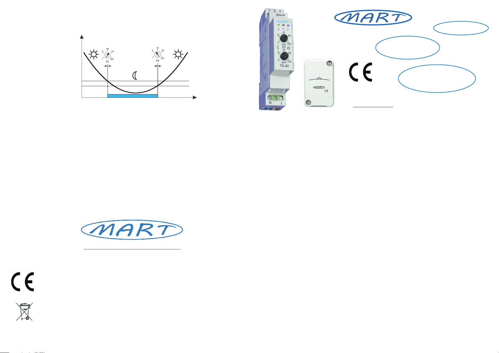
Fig. 3 .: Diagrams of the operation principles of the TS-42-4 TWILIGHT SWITCH.
t
E
ON OFF
User manual
I. Purpose
The TWILIGHT SWITCH TS-42-4 is designed to automatically switch the receiver on at the moment
it is dusk and turned off at dawn, or vice versa (NO, NC contacts). Two independent knobs for setting the
switch-on and switch-off thresholds allow for an optimal way to control the lighting. Independent adjustment of
the activation thresholds corrects the location of the sensor (north, south, east, west) and eliminates the
hysteresis that occurs in standard automatic units. Hysteresis causes switching off the lighting in the morning
when the lighting intensity is higher (2 ÷ 3 times) than the set lighting intensity level at which the lighting was
turned on. This causes an unfavourable extension of the lighting operation time in the morning, which results in
an increased consumption of electricity. On the other hand, too little hysteresis means that on cloudy days the
lamp may turn on and off with changing weather conditions, which is not advisable, and sometimes even
unacceptable for some lamps.
The light intensity measurement sensor has a spectrum similar to that of the human eye, and the adjustment
thresholds have logarithmic characteristics - also similar to the characteristics of the human eye.
Such an innovative design of the TS-42-4 TWILIGHT SWITCH makes the lighting control optimal, economic
and ecological.
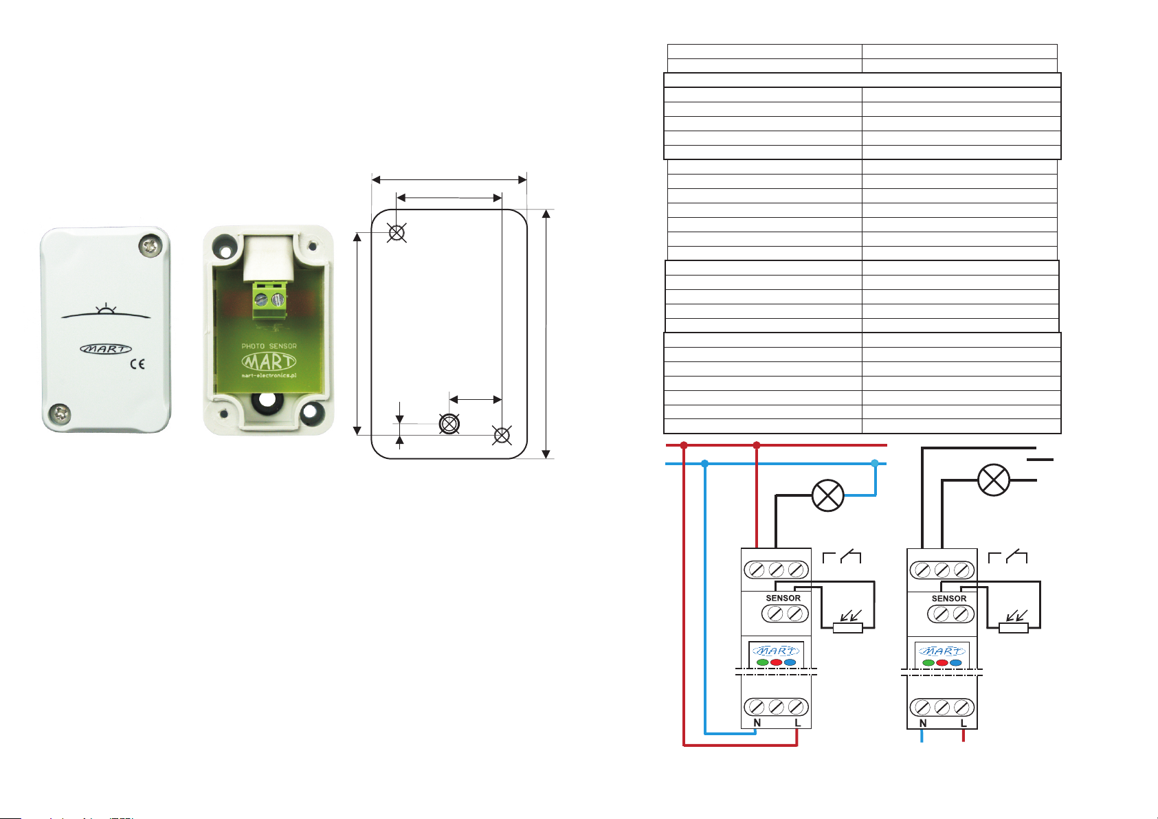
The TS-42-4 TWILIGHT SWITCH includes:
>> TS-42 CONTROLLER - mounted in a distribution box on a 35 mm rail (one 18 mm module)
>> OUTDOOR SENSOR (IP65) - surface-mounted box with a 5 mm rubber grommet on the rear wall,
mounted vertically with two screws. Connection cable not longer than 100m (2x0.5mm2).
II. Properties of the TS-42-4 ECO TWILIGHT SWITCH
>> Independent regulation of activation and deactivation thresholds
>> precise logarithmic adjustment:
> activation - 1 ... 10 ... 100 lx
> shutdown - 1 ... 10 ... 100 lx
>> high switching power - 16A (4000 W) 250VAC, 16A (384 W) 24VDC
>> high inrush current - resistance to 100 A surge current
>> freedom of connections:
> executive relay contacts (one normally open contact - NO, one normally closed contact - NC) galvanically
separated, which allows connections in various configurations
>> traffic light (LED):
> Green LED - indication of 230V AC supply voltage on LN terminals
> LED red:
- pulsating signalling (without delay) - the set (set) actuation threshold is exceeded
- continuous light - the level of the measured illuminance is between the settings on
knobs
> Blue LED - changeover indication - switching on (contact 1-2), disconnection (contact 2-3)
>> 35mm rail mount - one 18mm module.
The TS-42-4 CONTROLLER uses a specialized OMRON G2RL-1-E-HR relay, designed to switch various
types of lighting lamps. The special design of the relay enables effective switching of lamps with an inrush
current up to 100 A.
TS-42-4 ECO
TWILIGHT SWITCH
MADE IN EUROPE
3-YEAR
WARRANTY
FIRST
ECO
III. Assembly
The TS-42-4 TWILIGHT SWITCH device may only be connected by a person authorized to operate
electrical installations. Remember to choose the right protection.
On the front panel of the TS-42 CONTROLLER, there are three information LEDs: green, red, blue and two
knobs for setting the activation thresholds in the ranges from 1 to 100 lux. There are connection diagrams and
regulation characteristics on the side walls of the TS-42-4 CONTROLLER.
In order to connect the TS-42-4 TWILIGHT SWITCH:
1. Install the TS-42 CONTROLLER in the switchboard on a 35 mm rail
2. Fix the SENSOR on a vertical wall with two screws.
Insert the connection cable through the rubber grommet
located on the back wall of the installation box.
Screw the wires to the terminal block.
Fig. 2 .: Connection diagrams for the TS-42-4 TWILIGHT SWITCH automatic device.
1 2 3
TS-42
230VAC
16A 250VAC
16A 24VDC
(peak 100A)
23
N
L
1 2 3
~
16A 250VAC
(peak 100A)
1 2 3
1
TS-42
230VAC
3. Connect the wires in accordance with the diagram (fig. 2)
4. turn on the supply voltage - the green LED will light up and the red and blue LEDs will blink twice
5. set the activation thresholds.
When, during dimming, the level set on the ON knob is exceeded, the red LED will start to “blink” (without
delay), and after approx. 60 seconds the operating relay will switch, which will be signalled by the blue LED.
The activation delay of 60s should be counted from the moment of stable flashing of the red LED.
Using the control knobs, set the desired value of the switch-on threshold ON and switch-off OFF. Check
operation of TWILIGHT SWITCH TS-42-4 and possibly correct the setting in real conditions (in the evening and
in the morning). A red LED shining with a constant signal informs that the intensity of illumination falling on the
sensor is in the range between the set positions of the knobs. In order for the TWITLIGHT SWITCH device to
work properly, the measured illumination intensity must be lower at night from the lowest setting, the red LED
will turn off.
It should be remembered that the optimal setting of the activation thresholds has an impact on the costs of
electricity used and contributes to environmental protection.
In order to limit the impact of temporary large changes in lighting, for example, car lamps, lightning flash,
etc. on the operation of the TWILIGHT SWITCH, an actuation delay (approx. 60s) has been applied.
When setting the activation thresholds ON, OFF, remember that on a sunny day, covering the sensor with a
bare hand may not be sufficient. Then you should cover the SENSOR more effectively.
The pictorial diagram of the TS-42-4 TWILIGHT SWITCH operation principle is shown in Fig. 3.
NOTE: Avoid mounting the SENSOR directly in the light beam of the lamp being switched on, because lighting
with the SENSOR lamp may interfere with operation - the lamp will be switched on periodically
and turned off from evening until morning. This effect will not occur if the threshold on the OFF knob is set
higher than the illuminance level of the lamp that illuminates the sensor.
Fig 1. Photosensitive sensor - design, dimensions, template
40 mm
64 mm
52 mm
27 mm
h = 30 mm
1:1
4 mm
14 mm
IV. Technical data
Rated supply voltage LN
Rated frequency
Maximum load current (power):
> resistive load
> incandescent lamps
> halogen lamps
> fluorescent lamps
> energy-saving lamps and LED
Instantaneous inrush current
Executive contacts
Rated power consumption
Logarithmic control range ON
Logarithmic control range OFF
Switch-on and switch-off delay
CONTROLLER protection level
Installation of the CONTROLLER
CONTROLLER work position
CONTROLLER working temperature
CONTROLLER weight
SENSOR protection class
SENSOR dimensions
SENSOR assembly
SENSOR working position
Cable length to the SENSOR
SENSOR working temperature
230V AC, + 10%, - 15%
50Hz
16A, AC1 (4 000 W)
10A (2500 W)
8A (2000 W)
8A (2000 W)
8A (2000 W)
100A
1 x NO, 1 x NC
0,7 W
1...10...100 lx
1...10...100 lx
60s (± 10%)
100 000 operations
IP 20
One 18 mm field, 35 mm rail
Vertical
-25...+50 °C
50g
IP 65
40mm x 30mm x 64mm
Two screws
Vertical
2
Max 100 m (2 x 0,5 mm )
-25...+50 °C
50g
SENSOR weight
Why is it worth using for ECOLOGICAL and ECONOMICAL lighting control
TWILIGHT AUTOMATIC TS-42 series.
In general, lighting should be turned on optimally, that is, turned on when it is dark enough and turned off when
it is bright enough. Seemingly simple, but not entirely.
The correct lighting control is influenced by:
>> changeable weather conditions
>> switch on threshold setting
>> switch off threshold setting
>> hysteresis
>> characteristics of the illuminance measurement sensor
>> regulatory characteristics
CHANGING ATMOSPHERIC CONDITIONS
The weather conditions at sunrise and sunset vary throughout the year. Sunrises and sunsets are slow-
changing phenomena, and with cloudy twilight and sunrise, the intensity of lighting changes in a random and
unpredictable manner. A TWILIGHT SWITCH should be designed to take this into account.
SENSOR POSITIONING
THE TWILIGHT SWITCH LIGHT SENSOR is usually mounted where there is a lamp or a convenient place for
installation. Most often, we do not have much choice as to the direction of the sun's incidence on the sensor
(north, south, east, west). Therefore, the possibility of independently set activation and deactivation thresholds
corrects such a situation and enables the selection of optimal actuation parameters.
HYSTERESIS
Each typical TWILIGHT SWITCH has a hysteresis, which means that if we set the switch-on threshold (in the
evening) 30 lux, the switch-off threshold (in the morning) will be at OFF = 2 x ON, i.e. 60 lux. Too little
hysteresis will result in uncontrolled switching on and off of the lighting along with the change of weather
conditions. This is an undesirable effect, and even unacceptable with some lamps.
SENSOR POSITIONING

Other Mart Switch manuals

Mart TS-31-2-G.4 User manual

Mart

Mart TS-31-2-G.4 User manual

Mart TS-42-3 ECO User manual

Mart

Mart TS-42-3 ECO User manual

Mart TS-21 User manual

Mart

Mart TS-21 User manual

Popular Switch manuals by other brands

KTI Networks KS-116 installation guide

KTI Networks

KTI Networks KS-116 installation guide

Omega Engineering PSW495B installation instructions

Omega Engineering

Omega Engineering PSW495B installation instructions

WTI RPC Series Hardware guide

WTI

WTI RPC Series Hardware guide

Exsys EX-1198VS manual

Exsys

Exsys EX-1198VS manual

AVT 1815 quick guide

AVT

AVT 1815 quick guide

hager EE701 User instructions

hager

hager EE701 User instructions

EnGenius EWS Series user manual

EnGenius

EnGenius EWS Series user manual

Cisco SLM248P quick start guide

Cisco

Cisco SLM248P quick start guide

Allied Telesis x310-26FT Command reference

Allied Telesis

Allied Telesis x310-26FT Command reference

TRENDnet TK-210K Specifications

TRENDnet

TRENDnet TK-210K Specifications

D-Link xStack DGS-3420 Series reference guide

D-Link

D-Link xStack DGS-3420 Series reference guide

Hewlett Packard Enterprise StorageWorks 8/8 Base SAN Switch reference guide

Hewlett Packard Enterprise

Hewlett Packard Enterprise StorageWorks 8/8 Base SAN Switch reference guide

LevelOne GSW-0800TXM user manual

LevelOne

LevelOne GSW-0800TXM user manual

Valcom V-2972 manual

Valcom

Valcom V-2972 manual

Hugo Müller PALADIN 922 000 instruction manual

Hugo Müller

Hugo Müller PALADIN 922 000 instruction manual

Inficon VSA100A operating manual

Inficon

Inficon VSA100A operating manual

NTI UNIMUX Series Installation and operation manual

NTI

NTI UNIMUX Series Installation and operation manual

SOR 102 General instructions

SOR

SOR 102 General instructions

manuals.online logo
manuals.online logoBrands
  • About & Mission
  • Contact us
  • Privacy Policy
  • Terms and Conditions

Copyright 2025 Manuals.Online. All Rights Reserved.