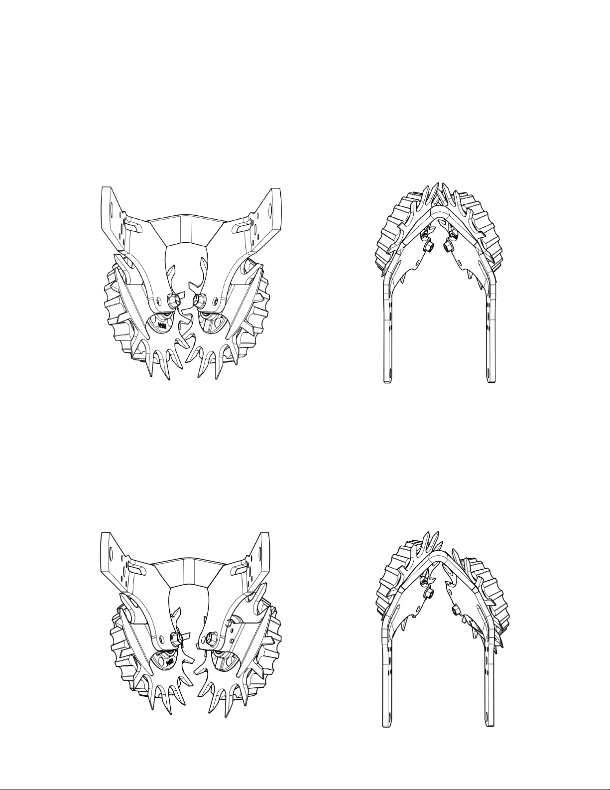
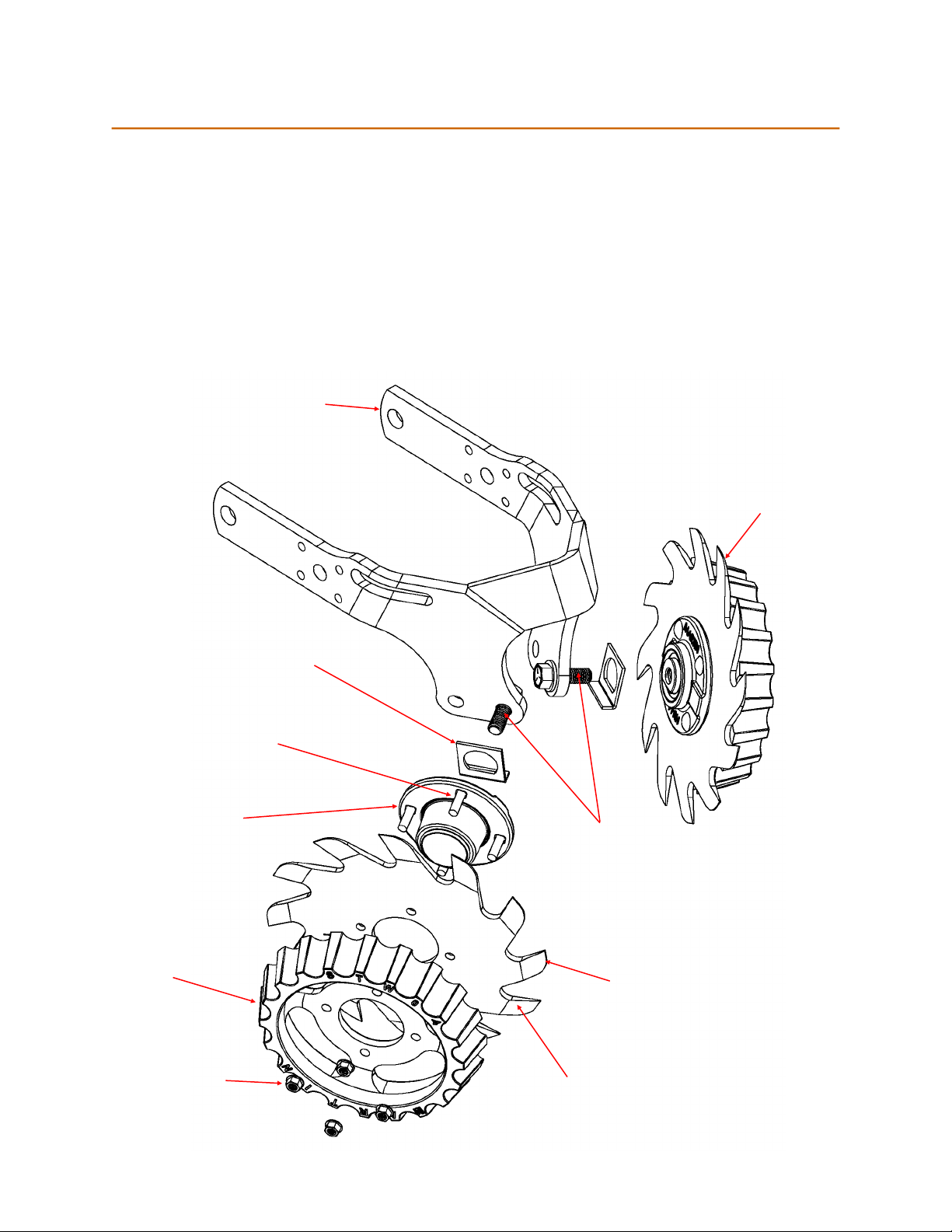
Offset Configuration
1. Place 5/8” x 1 3/4” flange patch bolt through rear hole of frame and torque to 112 ft-lbs, to secure an-
chor and hub axle to frame.
2. Place 5/16” x 1 1/4” BOLT, 5/16’ FLAT WASHER, 5/8” BUSHING, & 5/16” NUT in front hole of frame and
torque to 13 ft-lbs, to prevent anchor from rotating.
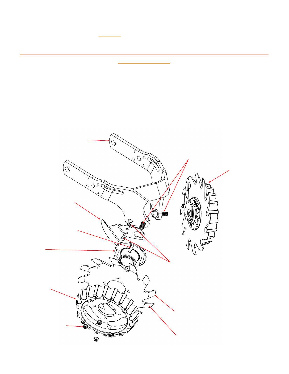
5/16” NUT
(N516CH)
5/16” x 1 1/4” BOLT AND FLAT
WASHER(B5m516NC114 &W516)
5/8” BUSHING
(SC-FR-SPACER)
5/16” NUT &
FLAT WASHER
(N516 &W516)
5/8” x 1 3/4” FLANGE
PATCH BOLT
(B5F58NC134)
5/16” x 1/2” BOLT
(B5m516NC12)
Smartclean Anchor
(SC-1360FR-MT-R)
5/16” x 1 1/4” BOLT AND FLAT
WASHER (B5m516NC114 &W516)
5/16” NUT and
Washer(N516
&W516)
5/8” x 1 3/4” FLANGE
PATCH BOLT
(B5F58NC134)
5/8” BUSHING
(SC-FR-SPACER)
Smartclean Anchor
(SC-1360FR-MT-R)
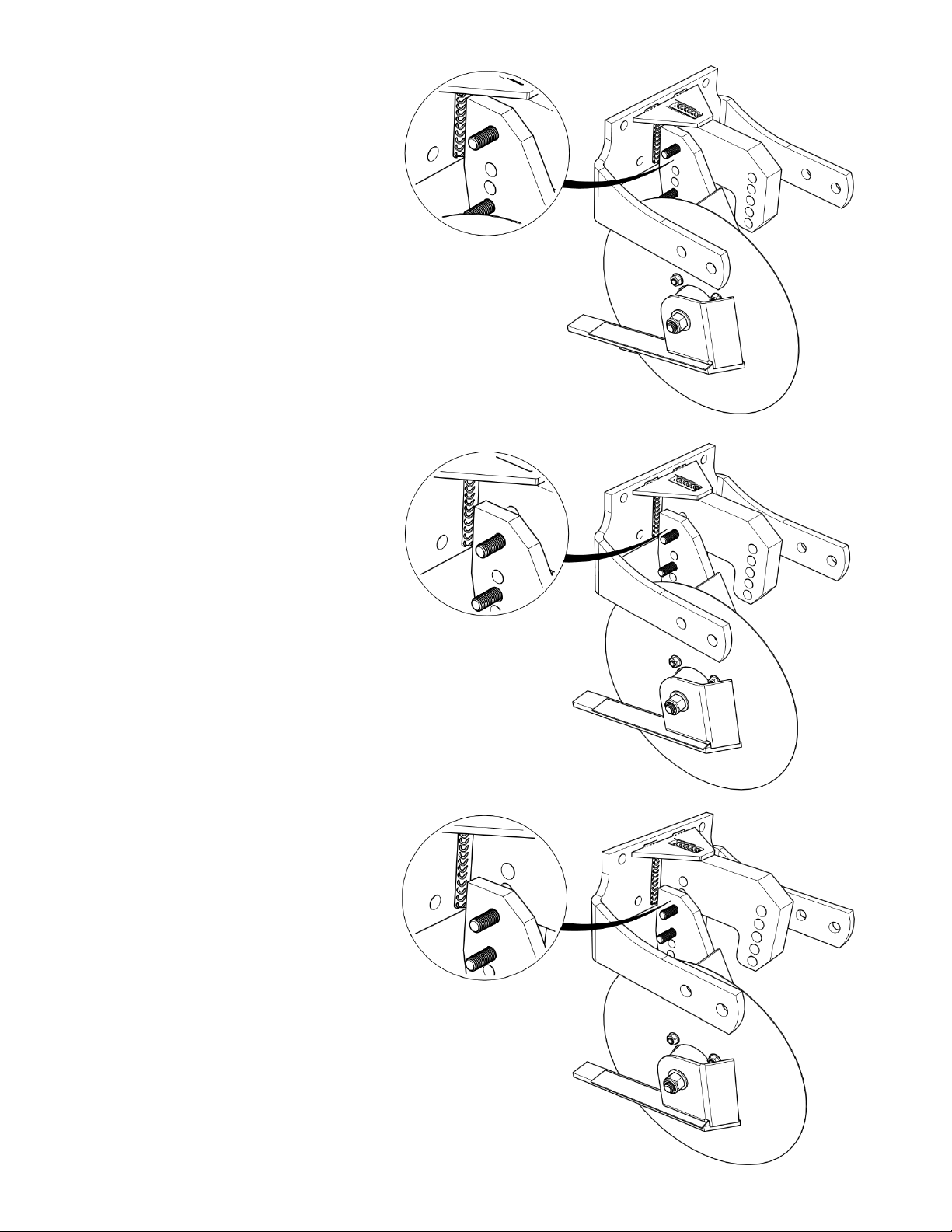
STEP 5: INSTALL SMART CLEAN CYLINDER BOTTOM ANCHOR
IMPORTANT: Skip to Step 6 if optional SmartClean System was not purchased
If the optional SmartClean cylinder was purchased, install the SmartClean cylinder bottom anchor, before in-
stalling the wheels, as shown below. Proper location of the bottom anchor mounting bolts is determined by
the wheel configuration you’ve chosen. The anchor is installed on the right side of the frame.
•
The first picture shows proper anchor mounting for the intersected wheel configuration.
•
The second picture shows proper anchor mounting for the offset wheel configuration.
Intersected Configuration
1. Place 5/8” x 1 3/4” flange patch bolt through front hole of frame and torque to 112 ft-lbs, to secure an-
chor and hub axle to frame.
2. Place 5/16” x 1 1/4 ” BOLT, 5/16” FLAT WASHER , 5/8” BUSHING & 5/16” NUT in rear hole of frame and
torque to 13 ft-lbs, to prevent anchor from rotating.
6