Martin Yale Titan User manual

Martin Yale Titan Model J2436
1.0 Introduction
Thank you for selecting the Martin Yale Titan –THE Professional Padding Press. We recommend that you
familiarize yourself with the Titan Padding Press by carefully reading these instructions. Thorough
understanding of the information contained within these instructions will help to eliminate most operator
associated errors and ensure years of trouble-free performance.
2.0 Assembly
2.1 Base Assembly
2.1.1 Refer to Parts List A and Diagram A. Locate Hardware Box and the large parts for
the Base Assembly. Open Hardware Box, remove casters and bag A. Set bags B
and C aside for now. Open bag A.
2.1.2 Attach Base Tray and Base Support to T-Frames as shown with “martin yale” decals
facing outward using the six (6) medium-length bolts, (6) lock washers and (6) acorn
nuts; tighten bolts.
2.1.3Insert the four (4) short bolts through the four (4) middle holes in Drip Tray and Tilt
Latch Assembly as shown, then install four (4) keps nuts; tighten bolts.
2.1.4 Note orientation of Drip Tray and Tilt Latch Assembly. Carefully slide Drip Tray/Tilt
Latch Assembly over the T-Frames and align four (4) outer holes. Insert four (4) long
bolts as shown, install (4) lock washers and (4) acorn nuts; tighten bolts.
2.1.5 Install casters as shown by carefully laying the base assembly on its side. Each T-
Frame should have one (1) locking caster and one (1) non-locking caster.
2.2 Upper Assembly
2.2.1 Refer to Parts List B and Diagram B. Locate Bag B, the L-Frames and the Bottom
Panel. Open parts bag B.
ATTENTION! Note the orientation of the L-Frames in Diagram B. Failure to install the
L-Frames in the proper orientation will cause the unit to not function
properly.
2.2.2 Install each L-Frame individually using shoulder bolt and nylon washer in the
orientation shown; tighten shoulder bolt using hex-key wrench.
2.2.3 Position Bottom Panel in the orientation shown, noting the location of notches on
front. Loosely install six (6) screws with six (6) keps nuts. Before tightening, position
Upper Assembly upright and verify Tilt Latch locks into place. This will result in an
audible click, and the assembly will no longer tilt. Tighten screws.
ATTENTION! Be careful after removal of the L-Frame Shipping Braces to not bend or
otherwise damage the L-Frames.
2.2.4 Remove (2) screws securing each L-Frame Shipping Braces at top of each L-Frame.
Discard screws and braces.
2.2.5 Carefully slide one (1) clamp onto each L-Frame as shown, ensuring clamp is
installed onto front tube. Do not bend L-Frames!
M-S027946 Rev. 2 8/15/14
ProSource Packaging, Inc.
14911 Stuebner Airline Suite A
Houston, TX 77069
800-203-0233
www.Machine-Solution.com

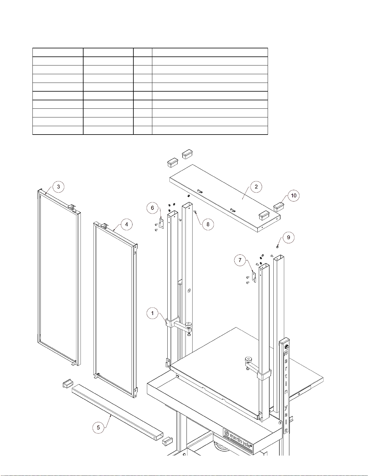
2.2.6 Refer to Parts List C and Diagram C. Locate Top Panel; Doors. Open parts bag C.
2.2.7 Locate hinges in parts bag. Position as shown, ensuring correct hinge is on each
frame, and install using two (2) screws and two (2) keps nuts for each hinge.
2.2.8 Position the Top Panel Assembly as shown and install using four (4) screws and four
(4) keps nuts. Be careful not to bend L-Frames in the process! Tighten screws.
At this point, the Upper Assembly and L-Frames are no longer at risk for bending.
2.2.8 Insert four (4) tubing End Caps into each of the tubing ends near the Top Panel.
2.2.10 Noting orientation of doors, carefully position and slide doors onto Lift Hinge Pins on
Upper Assembly. Close doors and verify they latch into place. Lock doors by hooking
the Draw Latch clasp over the keeper and snapping into place.
Congratulations! Your brand new
Martin Yale Titan –THE Professional Padding Press
is now ready for use!
3.0 Operation
NOTE: For best results, all material should be jogged before padding.
Martin Yale Model 400 or Model 4200 Jogger is recommended.
3.1 Lock casters by pressing down with foot to keep the unit from moving.
3.2 Verify Upper Assembly is locked in the upright position and doors are locked.
3.3 While standing on the left side of the Titan, hold Upper Assembly with left hand while pulling
Tilt Latch up with right hand. When the latch opens, tilt Upper Assembly down and release
latch. Verify the latch has locked the Upper Assembly into place.
3.4 Slide each clamp up to Top Panel and position so that clamp handle rests on Clamp Latch.
3.5 Square the paper into the corner(s) and lightly press against the door(s). Place Clamp Tube
on top of the paper stack(s) and against doors.
3.6 Lower Clamps to Clamp Tube and tighten clamp knobs by hand. Do not use tools such as
wrenches or pliers!
3.4 Unlock and open doors. Apply padding compound to facing edge of paper stack. When dry,
release clamps to remove pad(s).
3.5 For Carbonless Paper
The Titan is constructed so that the Clamp Bar can be set on the edge of the paper for little
penetration or moved away from the edge so that carbonless padding compound can
penetrate further into the sheets. If you are doing snap-outs in carbonless forms, you can
move the Clamp Bar in about 1/4“ and padding compound will penetrate just as well as if
you used a tipping machine.
4.0 Maintenance
Clean unit when needed with warm, soapy water. Doors are installed with Lift Hinges for easy removal and
cleaning; with the Upper Assembly locked in the upright position, unlock and open each door and carefully
pull the door upward and away from the Upper Assembly. Do not use the same brush for regular and
carbonless padding compounds. A paper liner can be used in Drip Tray to minimize clean up.
251 Wedcor Drive • Wabash, IN 46992
Phone (260) 563-0641 • Fax # (260) 563-4575
Website: www.martinyale.com • Email: info@martinyale.com
M-S027946 Rev. 2 8/15/14

Parts List A
Item # Part # Qty. Description
1
W-O243615
2
T-Frame
2
W-O243617
1
Base Support
3
W-O243619
1
Base Tray
4
W-O243621
1
Drip Tray
5
W-O243623
1
Tilt Latch Assembly
6
M-S001062
4
Short Bolt (¼-20 X 5/8)
7
M-S001548
6
Mid-Length Bolt (¼-20 X 1.25)
8
M-S001547
4
Long Bolt (¼-20 X 2.25)
9
M-S008029
10
Lock Washer (¼ Internal)
10
M-S007133
10
Acorn Nut (¼-20)
11
M-S63251449
4
Keps Nut (¼-20)
12
M-S034009
2
Swivel Caster
13
M-S034010
2
Locking Swivel Caster
Parts Diagram A

Parts List B
Item # Part # Qty. Description
1
W-O243637
1
Right L-Frame
2
W-O243639
1
Left L-Frame
3
W-O243657
1
Bottom Panel
4
M-S003140
2
Shoulder Bolt (.50 X 2.00)
5
M-S008100
2
Nylon Washer (.503 ID)
6
M-S001022
6
Screw (10-32 X 3/8)
7
M-S007008
6
Keps Nut (10-32)
Parts Diagram B

Parts List C
Item # Part # Qty. Description
1
W-O243649
2
Clamp
2
W-O243663
1
Top Panel Assembly
3
W-O243669
1
Right Door
4
W-O243669
1
Left Door
5
W-O243675
1
Clamp Bar
6
M-S036011
1
Right Hinge
7
M-S036010
1
Left Hinge
8
M-S001022
8
Screw (10-32 X 3/8)
9
M-S007008
8
Keps Nut (10-32)
10
M-S043744
4
End Cap
Parts Diagram C
This manual suits for next models
1
Table of contents
Other Martin Yale Power Tools manuals
Popular Power Tools manuals by other brands

Sparky Group
Sparky Group FSPE 80 Original instructions

Delta Regis
Delta Regis ESB6-RA30 Operation manual

Eagle
Eagle EGA200 owner's manual

Tohnichi
Tohnichi CTB10N2X8D-G operating instructions

Proluxe
Proluxe Flex X1 Operation manual

PCB Piezotronics
PCB Piezotronics GK291E80 Installation and operating manual