Martindale Electric CM100 User manual

CM100
FLEX CLAMP METER
Instruction
Manual
GENERAL SAFETY INFORMATION: Always read before proceeding.
Warning
These instructions contain both information and warnings that are necessary for the
safe operation and maintenance of this product. It is recommended that you read the
instructions carefully and ensure that the contents are fully understood. Failure to
understand and to comply with the warnings and instructions can result in serious
injury, damage or even death.
In order to avoid the danger of electrical shock, it is important that proper safety
measures are taken when working with voltages exceeding 30V AC rms, 42V AC
peak or 60V DC.
This product must only be used by a competent person capable of interpreting the
results under the conditions and for the purposes for which it has been constructed.
Particular attention should be paid to the Warnings, Precautions and Technical
Specifications. Always check the unit is in good working order before use and that
there are no signs of damage to it. Do not use if damaged.
Where applicable other safety measures such as use of protective gloves, goggles
etc. should be employed.
Please keep these instructions for future reference. Updated instructions and
product information are available at: www.martindale-electric.co.uk
REMEMBER: SAFETY IS NO ACCIDENT
MEANING OF SYMBOLS:
Equipment complies with relevant EU Directives
End of life disposal of this equipment should be
in accordance with relevant EU Directives
Caution - risk of electric shock
Caution - risk of danger & refer to instructions
Equipment protected by double or reinforced insulation (Class II)
Alternating current (AC).
Do not apply around or remove from uninsulated hazardous live
conductors, which may render electric shock, electric burn, or arc
flash.
Thank you for buying one of our products. For safety and full
understanding of its benefits please read this manual before use.
Technical support is available from 01923 441717 and
support@martindale-electric.co.uk.
CONTENTS
1 Introduction 1
1.1 Inspection 1
1.2 Description 1
1.3 Accessories 1
1.4 Battery Installation 1
2 Product Specific Safety Information 2
2.1 Precautions 2
3 Operation 4
3.1 General 4
3.2 Low Battery Indication 4
3.3 Description of Press Buttons 4
3.4 Description of LCD Symbols 4
3.5 Auto Power Off 4
3.6 Display Hold 5
3.7 Min/Max 5
3.8 Backlight 5
3.9 AC Current Measurement 5
3.10 Position Sensitivity 6
4 Maintenance 7
4.1 Battery Replacement 7
4.2 Calibration 7
4.3 Cleaning 7
4.4 Repair & Service 8
4.5 Storage Conditions 8
5 Warranty 9
Specifications 1
1. INTRODUCTION
1.1 Inspection
Examine the shipping carton for any sign of damage. Inspect the
unit and any accessories for damage. If there is any damage then
consult your distributor immediately.
1.2 Description
The CM100 is an AC current meter with a flexible current sensor
capable of measuring true rms AC current up to 3000A in 3 ranges.
The CM100 is particularly suited to measuring current in awkwardly
shaped or positioned conductors where access by conventional
clamp meters may prove difficult.
The CM100/18 is fitted with an 18” flexible sensor and the
CM100/60 is fitted with a 60” flexible sensor.
Further functions are:
Min/Max indication
Display backlight
Display hold
Auto power off
1.3 Accessories
The CM100 comes with the following accessories:
2 x 1.5V AAA batteries
Instructions
1.4 Battery Installation
Refer to Section 4.1 (Battery Replacement) for the battery
installation instructions for the CM100.

2
2. PRODUCT SPECIFIC SAFETY INFORMATION
Measurement Category III (CAT III) is applicable to test and
measuring equipment connected to the distribution part of the
building’s low-voltage MAINS installation.
Measurement Category IV (CAT IV) is applicable to test and
measuring equipment connected at the source of the building’s low-
voltage MAINS installation.
The specified measurement category means the flexible current
meter will be safe to the user when used on CAT IV installations up
to 600V and CAT III installations up to 1000V.
2.1 Precautions
This product has been designed with your safety in mind, but please
pay attention to the following warnings and cautions before use.
Warnings
Before use check the unit for cracks or any other damage. Make
sure the unit is free from dust, grease and moisture. Also check
any associated leads and accessories for damage. Do not use if
damaged.
The flexible sensor has contrasting outer and inner insulation
to allow damage to the cable to be easily identified. If the inner
insulation can be seen, the flexible current meter must not be
used.
When working on uninsulated hazardous live installations, always
de-energise the installation during application and removal of the
flexible current sensor.
Do not use if the battery cover is not fitted. 3
Cautions
Avoid severe mechanical shock or vibration and extreme
temperature.
Remove the batteries when not in use for an extended period, to
avoid corrosion from leaking batteries.
4
3. OPERATION
3.1 General
If the magnitude of a parameter to be measured is unknown, but
known to be within the maximum safe limits of the meter, set the
range to maximum. E.g. If measuring AC current and the AC current
magnitude is unknown, set the range to 3000 A.
If the meter displays “– OL.–” the measurement limits of the range
have been exceeded.
3.2 Low Battery Indication
If the symbol is displayed, the battery needs replacing as
measurement accuracy can no longer be guaranteed (See section
4.1 Battery Replacement).
3.3 Description of Press Buttons
HOLD Selects display hold
MIN
MAX Selects maximum/minimum function
Turns on/off backlight
3.4 Description of LCD Symbols
MAX The maximum reading is being displayed
MIN The minimum reading is being displayed
HOLD Display hold is activated
AUnit of measurement being displayed
Indicates low battery
Auto power off is activated
Indicates AC measurement
3.5 Auto Power Off
If the meter is inactive for a period of 15 minutes it will automatically
power off.
5
If any button is pressed after the clamp meter has automatically
powered off, the clamp meter will turn back on.
To disable the auto power off function hold down the HOLD button at
the same time as turning the rotary switch from OFF to any position.
The symbol will no longer be displayed on the LCD.
3.6 Display Hold
To hold a displayed value, press the HOLD button. The LCD will
display HOLD.
To exit display hold, press the HOLD button again.
3.7 Min/Max
To display the maximum measured value press the MIN
MAX button.
The LCD will display MAX.
To display the minimum measured value press the MIN
MAX button
again. The LCD will display MIN.
Pressing the MIN
MAX button for a third time will return the meter to a
normal display mode with maximum and minimum measured values
being stored. The LCD will display MAX MIN flashing.
To exit the Min/Max function, press the MIN
MAX button for 2 seconds.
3.8 Backlight
To switch on the backlight press the button. Press again to turn
the backlight off.
3.9 AC Current Measurement
Set the rotary switch to the 30A, 300A or 3000A range as required.

6
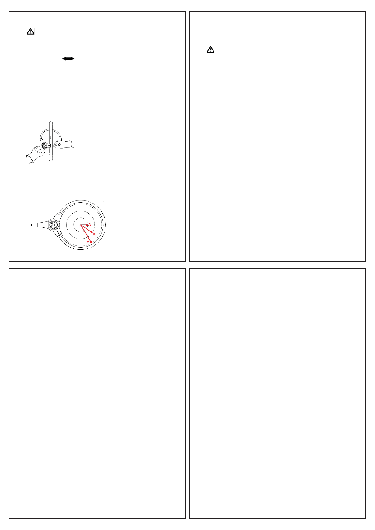
Always de-energise an uninsulated hazardous live conductor
under test before positioning the flexible current sensor around it.
Pull and unclip the flexible sensor from the sensor coupling at the
end marked with .
Referring to figure 1, and taking all necessary safety precautions,
wrap the flexible sensor around the conductor to be measured and
clip the flexible sensor end back into the sensor coupling.
Position the flexible sensor so the conductor under test is at the
centre of the sensor loop and perpendicular to the sensor loop.
Read the measured current from the display.
3.10 Position Sensitivity
If it is not possible to position the flexible sensor so the conductor
is at the centre of the loop, the measured value will have additional
errors dependant on the position of the conductor in the sensor loop.
See figure 2.
Figure 1
Figure 2
7
4. MAINTENANCE
4.1 Battery Replacement
To avoid shock or injury, disconnect the flexible sensor from any
external circuits before proceeding.
The battery compartment is underneath the unit.
To gain access, undo the screw securing the battery compartment
cover, then lift off the cover.
Fit 2 new 1.5V AAA alkaline batteries (IEC LR03, NEDA 24A).
Replace the battery cover and the screw.
Note: Do not mix old and new batteries.
4.2 Calibration
To maintain the integrity of measurements made using your
instrument, Martindale Electric recommends that it is returned
at least once a year to an approved Calibration Laboratory for
recalibration and certification.
Martindale Electric is pleased to offer you this service. Please
contact our Service Department for details.
Email: service@martindale-electric.co.uk
Tel: 01923 650660
4.3 Cleaning
The unit may be cleaned using a soft dry cloth. Do not use moisture,
abrasives, solvents, or detergents, which can be conductive.
8
4.4 Repair & Service
There are no user serviceable parts in this unit other than those that
may be described in section 3. Return to Martindale Electric if faulty.
Our service department will quote promptly to repair any fault that
occurs outside the guarantee period.
Before the unit is returned, please ensure that you have checked
the unit and batteries.
4.5 Storage Conditions
The instrument should be kept in warm dry conditions away from
direct sources of heat or sunlight, and in such a manner as to
preserve the working life of the unit. It is strongly advised that the
unit is not kept in a tool box where other tools may damage it.
9
5. WARRANTY AND LIMITATION OF LIABILITY
This Martindale product is warranted to be free from defects in material
and workmanship under normal use and service. The warranty period is
2 years and begins on the date of receipt by the end user. This warranty
extends only to the original buyer or end-user customer, and does
not apply to fuses, disposable batteries, test leads or to any product
which, in Martindale’s opinion, has been misused, altered, neglected,
contaminated, or damaged by accident or abnormal conditions of
operation, handling or storage.
Martindale authorised re-sellers shall extend this warranty on new and
unused products to end-user customers only but have no authority to
extend a greater or different warranty on behalf of Martindale.
Martindale’s warranty obligation is limited, at Martindale’s option, to refund
of the purchase price, free of charge repair, or replacement of a defective
product which is returned to Martindale within the warranty period.
This warranty is the buyer’s sole and exclusive remedy and is in lieu of
all other warranties, expressed or implied, including but not limited to any
implied warranty of merchantability or fitness for a particular purpose.
Martindale shall not be liable for any special, indirect, incidental or
consequential damages or losses, including loss of data, arising from any
cause or theory.
Since some jurisdictions do not allow limitation of the term of an implied
warranty, or exclusion or limitation of incidental or consequential
damages, the limitations and exclusions of this warranty may not apply
to every buyer. If any part of any provision of this warranty is held invalid
or unenforceable by a court or other decision-maker of competent
jurisdiction, such holding will not affect the validity or enforceability of any
other provision or other part of that provision.
Nothing in this statement reduces your statutory rights.

Specication
CM100
Flexible Current Meter
ELECTRICAL
All specified accuracies are at 23°C ± 5°C, <80% RH for 1 year.
Temperature Coefficient: 0.1 x (specified accuracy) per °C. (0°C to 18°C, 28°C
to 40°C).
Range Resolution Accuracy (45 Hz to 500 Hz)
30 A 0.01 A
± (3.0 % of rdg + 5 dgts) Note 1
300 A 0.1 A
3000 A 1 A
AC conversion: True rms.
True rms AC current accuracy is specified from 2 % of range to 100 % of
range.
Crest factor: d1.6 at full scale (30.00A/300.0A/3000A).
d3.2 at half scale (15.00A/150.0A/1500A).
Note 1: Measurement accuracy assumes a centrally positioned conductor, no
external electrical or magnetic field and within operating temperature range.
See figure 2 and the position sensitivity error table below for additional errors
where the conductor is not centrally positioned.
Position from
loop centre
(refer to figure 2)
CM100/18 CM100/60
Distance Error Distance Error
A 1” (2.54cm) 1.0 % 3” (7.6cm) 2.0 %
B 2” (5.1cm) 2.0 % 6” (15.2cm) 3.0 %
C 3” (7.6cm) 3.0 % 9” (22.9cm) 4.0 %
ENVIRONMENTAL
Operating environment: 0°C to 50°C, <80% RH, non-condensing
Storage temperature: -10°C to 60°C, 70% RH
Altitude: Up to 2000m
GENERAL
Display: Liquid crystal display with a maximum reading of 3150 digits.
Overrange: “–OL–” is displayed
Low battery indication: symbol is displayed when the battery voltage drops
below the operational level
Sampling rate: 2 times per second.
Auto power off: After approx. 15 minutes
Power: 2 x 1.5 V AAA batteries (IEC LR03, NEDA 24A)
Battery life: 120 hours typical with alkaline
Dimensions:
Meter: 120mm (L) x 70mm (W) x 26mm (D)
Probe cable length: 457mm (CM100/18), 1524mm (CM100/60)
Probe cable diameter: 8.5mm nominal
Cable length (probe to meter): 1.8m
Weight: 286g approx. including batteries
Includes: 2 x 1.5V AAA batteries and instructions
SAFETY
Conforms to BS EN 61010-1, BS EN 61010-2-032, CAT IV 600V,
CAT III 1000 V
Class II, Double Insulation
Pollution Degree: 2
EMC
Conforms to BS EN 61326-1
Check out what else you can get from Martindale:
Martindale Electric Company Limited
Metrohm House, Penfold Trading Estate, Imperial Way, Watford WD24 4YY, UK
Tel: +44(0)1923 441717 Fax: +44 (0)1923 446900
E-mail: sales@martindale-electric.co.uk
Website: www.martindale-electric.co.uk
© 2013 Martindale Electric Company Ltd.
Registered in England No. 3387451. E. & O.E. Document Rev1 LITCM100
• 17th Edition Testers
• Accessories
• Calibration Equipment
• Continuity Testers
• Electricians’ Kits
• Environmental Products
• Full Calibration & Repair Service
• Fuse Finders
• Digital Clamp Meters
• Digital Multimeters
• Labels
• Microwave Leakage Detectors
• Motor Maintenance Equipment
• Multifunction Testers
• Non-trip Loop Testers
• Pat Testers & Accessories
• Phase Rotation Testers
• Proving Units
• Socket Testers
• Thermometers & Probes
• Test Leads
• Voltage Indicators
• Specialist Metrohm Testers (4 & 5kV)
• Specialist Drummond Testers
Other Martindale Electric Measuring Instrument manuals

Martindale Electric
Martindale Electric PSI4000 User manual

Martindale Electric
Martindale Electric CM58 User manual

Martindale Electric
Martindale Electric CM55 User manual

Martindale Electric
Martindale Electric CM95 User manual

Martindale Electric
Martindale Electric LM195 User manual

Martindale Electric
Martindale Electric VT12 MK2 User manual