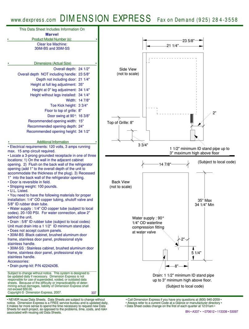
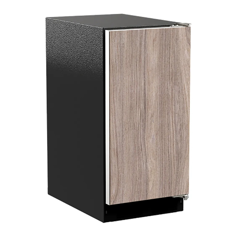
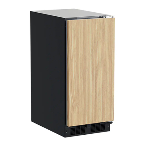
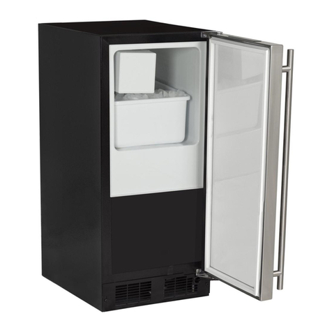
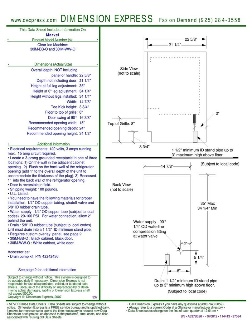
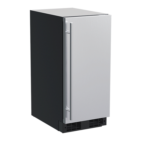
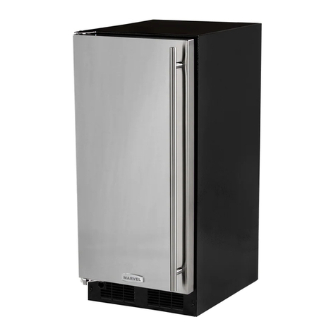
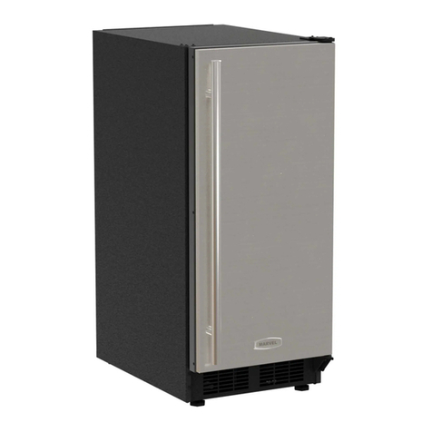
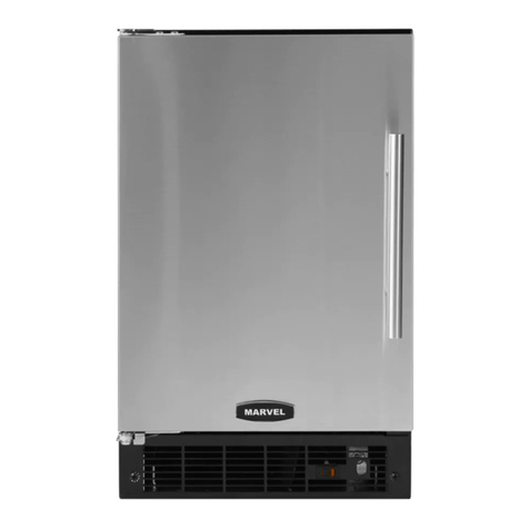
Marvel MPNP415-IS81A User manual

OWNER’S GUIDE & SERVICE MANUAL
MARVEL UNDERCOUNTER REFRIGERATION
Model: MPNP415-IS81A

WELCOMEWELCOME
Warranty Registration
It is important you send in your warranty registration card
immediately after taking delivery of your appliance or you
can register online at www.marvelrefrigeration.com.
The following information will be
required when registering your
appliance:
Service Number
Serial Number
Date of Purchase
Dealer’s name and address
The service number and serial number can be found on the
serial plate which is located inside the cabinet on the left
side near the top.
Online regis-
tration available at
www.marvelrefriger-
ation.com
XXXXXXXXXXXX
XXXXXXXXXXXX
MARVEL
g
R600A
Welcome to the Marvel Experience!
Thank you for choosing our quality American-built product
to add to your home. We are thrilled to welcome you to
our growing community of Marvel owners, who trust in our
products and our support.
The information in this guide is intended to help you install
and maintain your new Marvel undercounter model to pro-
tect and prolong its lifetime. We encourage you to contact
our Technical Support team at (616) 754-5601 with any
questions.
Got a Marvelous Design?
We would love to see how your Marvel product looks in
its new home. Send us photos at marketing@marvelre-
frigeration.com, and we might feature your Marvel home
design on our website and social media!
Bonus Third-Year Warranty Free with Product
Registration
Your Marvel Professional
product qualies for a one-year
extension of the two-year war-
ranty coverage from your date
of purchase, free of charge. To
take advantage of this third-year
warranty, be sure to reg-is-
ter your product with Marvel
within 60 days from the date
of purchase at marvelrefriger-
ation.com and provide proof of
purchase.
Thank you again for investing in Marvel for your home!

TABLE OF CONTENTS
Tip: Click on any section below to jump directly there
Safety
Important Safety Instructions
Installation
Unpacking Your Appliance
Electrical
Cutout & Product Dimensions
Side-by-Side & Stacking Installations
Door Reversal
Integrated Panel Dimensions
Integrated Panel Installation
Installing The Water Supply
Installing the Drain plumbing
Maintenance
Care and Cleaning
Extended Non-Use
Operating Instructions
Using Your Electronic Control
Ice Maker Operation
Service
Obtaining Service
Troubleshooting
Wire Diagram
Product Liability
Warranty Claims
Ordering Replacement Parts
R600a Specifications
System Diagnosis Guide
Control Operation - Service
Defrost
Remove Fan and Cover
Warranty
3

IMPORTANT SAFETY INSTRUCTIONSIMPORTANT SAFETY INSTRUCTIONS
Important Safety Instructions
Warnings and safety instructions appearing in this guide
are not meant to cover all possible conditions and situa-
tions that may occur. Common sense, caution and care
must be exercised when installing, maintaining or operating
this appliance.
Recognize Safety Symbols,
Words and Labels
NOTE
!CAUTION
CAUTION - Hazards or unsafe practices which could
result in personal injury or property/product damage.
NOTE - Important information to help assure a prob-
lem-free installation and operation.
!WARNING
WARNING - You can be killed or seriously injured
if you do not follow these instructions.
!WARNING
State of California Proposition 65 Warning:
This product contains one or more chemicals known
to the State of California to cause cancer.
!WARNING
State of California Proposition 65 Warning:
This product contains one or more chemicals known
to the State of California to cause birth defects or
other reproductive harm.
!WARNING
WARNING - This unit contains R600a (Isobutane)
which is a fl ammable hydrocarbon. It is safe for regular
use. Do not use sharp objects to expedite defrosting.
Do not damage refrigerant circuit.
4

UNPACKING YOUR APPLIANCE
!WARNING
EXCESSIVE WEIGHT HAZARD
Use two or more people to move product.
Failure to do so can result in personal injury.
Remove Interior Packaging
Your appliance has been packed for shipment with all parts
that could be damaged by movement securely fastened.
Remove internal packing materials and any tape holding in-
ternal components in place. The owners manual is shipped
inside the product in a plastic bag along with the warranty
registration card and other accessory items.
Important
Keep your carton and packaging until your appliance has
been thoroughly inspected and found to be in good condi-
tion. If there is damage, the packaging will be needed as
proof of damage in transit. Afterwards, please dispose of all
items responsibly.
Note to Customer
This merchandise was carefully packed and thoroughly
inspected before leaving our plant. Responsibility for its
safe delivery was assumed by the retailer upon acceptance
of the shipment. Claims for loss or damage sustained in
transit must be made to the retailer.
DO NOT RETURN DAMAGED MERCHANDISE TO THE
MANUFACTURER - FILE THE CLAIM WITH THE RETAIL-
ER.
NOTE
!WARNING
WARNING - Dispose of the plastic bags which can
be a suff ocation hazard.
!CAUTION
!WARNING
WARNING - Help Prevent Tragedies
Child entrapment and suff ocation are not problems of
the past. Junked or abandonded refrigerators are still
dangerous, even if they sit outside for “just a few hours”.
If you are getting rid of your old refrigerator, please fol-
low the instructions below to help prevent accidents.
Before you throw away your old refrigerator or freezer:
• Take off the doors or remove the drawers.
• Leave the shelves in place so children may not
• easily climb inside.
If the appliance was shipped, handled or stored in other
than an upright position for any period of time, allow the ap-
pliance to sit upright for a period of at least 24 hours before
plugging in. This will assure oil returns to the compressor.
Plugging the appliance in immediately may cause damage
to internal parts.
5
ELECTRICAL
NOTE
Electrical Shock Hazard
• Do not use an extension cord with this appliance.
They can be hazardous and can degrade product
performance.
• This appliance should not, under any circum-
stances, be installed to an un-grounded electrical
supply. Do not remove the grounding prong from
the power cord.
• Do not use an adapter.
• Do not splash or spray water from a hose on
the appliance. Doing so may cause an electrical
shock, which may result in severe injury or death.
!WARNING
Ground Fault Circuit Interrupters (GFCI) are prone to nui-
sance tripping which will cause the appliance to shut down.
GFCI’s are generally not used on circuits with power equip-
ment that must run unattended for long periods of time, un-
less required to meet local building codes and ordinances.
Electrical Connection
A grounded 115 volt, 15 amp dedicated circuit is required.
This product is factory equipped with a power supply
cord that has a three-pronged, grounded plug. It must be
plugged into a mating grounding type receptacle in accor-
dance with the National Electrical Code and applicable
local codes and ordinances. If the circuit does not have a
grounding type receptacle, it is the responsibility and obli-
gation of the customer to provide the proper power supply.
The third-ground prong should not, under any circumstanc-
es, be cut or removed.
Do not remove
ground prong
6

CUTOUT & PRODUCT DIMENSIONS
CUTOUT DIMENSIONS - MPNP415
´FXWRXWZLGWKPD\EHVXIILFLHQWLIRSHQLQJLVH[DFW
DQGVTXDUH
PRODUCT DIMENSIONS
REAR
FRONT
TOP
SIDE
7

SIDE-BY-SIDE AND STACKING INSTALLATIONS
Side-by-Side Installation
Other Site Requirements
Units must operate from separate, properly grounded elec-
trical receptacles placed according to each unit's electrical
To ensure unobstructed door swing (opening both doors at
the same time), 1/4" (6.4 mm) of space needs to be maint-
ained between the units.
Hinge-by-Hinge Installation (Mullion)
When installing two units hinge-by-hinge, 13/16" (22 mm)
is required for integrated models. Additional space may be
needed for any knobs, pulls or handles installed.
Stainless steel models which include the standard stainless
handle will require 4-9/16" (116 mm) to allow both doors to
open to 90° at the same time.
Figure 10
Figure 11
Figure 12
Figure 13
Hinge-by-Wall Installation
When installing a unit hinge-by-wall or adjacent cabinetry,
7/16” (11mm) is required for integrated models. Additional
space may be needed for any knobs, pulls or handles installed.
¼”
13/16”
7/16”
4-9/16”
8

INSTALLING THE ANTI-TIP DEVICE
Anti-Tip Bracket
Use one of the methods below to secure the unit
Cabinet/Counter Anti-Tip Installation
(For built-in applications)
1. Slide unit out so screws on front of unit are easily
accessible.
2. Remove the two screws from the front of the unit.
3. Bend bracket along one of the perforations to allow
attachment to the desired adjoining surface.
4. Gently push unit into position. Be careful not to entangle
the electrical cord or water line, if applicable.
5. Check to be sure the unit is level from front to back and
side to side. Make any necessary adjustments. The
unit’s top surface should be approximately ¹»” (3 mm)
below the countertop.
6. Secure bracket to adjoining surface.
Floor Mounted Anti-Tip Installation
(For free-standing applications)
1. Locate two anti-tip brackets included with the kit.
2. Place the unit into the area where it will be installed.
&KHFNWKHGRRUVLGHVDQGWRSIRUDSURSHU¿W$OVRWHVW
to make sure the door opens and closes freely.
3. 5HPRYHJULOOHDQGSODFHDPDUNRQWKHÀRRUDWWKHIURQW
RIWKHXQLW$OVRSODFHDPDUNRQWKHÀRRULQWKHFHQWHU
of the unit.
4. Remove the unit. Using a square, extend center line
“B” (see chart). This line serves as the back edge for
WKHDQWLWLSEUDFNHWV)URPWKHFHQWHUOLQHPHDVXUH³$´
to the left and right. This line is the outer edge of each
bracket.
C
L
Back wall
Back of unit
Front of unit
Surrounding
area (Top view)
AA
B
A7 ΑȟΞȓ
Bȓ
3ODFHWKHDQWLWLSEUDFNHWVRQWKHÀRRUDJDLQVWWKHOLQH
drawn for the outer edge. Mark spots for the screw holes.
C
L
Surrounding
area (Top view)
Drill holes and
mount anti-tip
brackets to floor Back wall
Front
of
unit
Back
of
unit
AA
B
6. Use a 1/8” drill to make two starter holes and fasten the
DQWLWLSEUDFNHWVWRWKHÀRRUXVLQJWKHVFUHZVSURYLGHG
7. Place the unit back into position, making sure the feet
engage the anti-tip brackets properly. Check the alignment
RIWKHOLQHVPDGHRQWKHÀRRULQVWHSZLWKWKHSRVLWLRQRI
the front feet to ensure proper positioning.
9

Integrated Panel Dimensions
'XHWRGLႇHUHQFHVLQVXUURXQGLQJFDELQHWU\WKHSDQHO
PD\QRWSHUIHFWO\DOLJQZLWKGRRU7KHSURFHGXUHEHORZ
LVGHVLJQHGWRSURYLGHD¿QLVKHGLQWHJUDWHGSDQHOWKDW
VHDPOHVVO\LQWHJUDWHVZLWKVXUURXQGLQJFDELQHWU\
7KHGRRUSDQHOPXVWQRWZHLJKPRUHWKDQOEVNJ
,WLVLPSRUWDQWWRHQVXUHWKDWDOOGULOOHGKROHVDUHGULOOHGWR
WKHFRUUHFWGHSWKLQRUGHUWRDYRLGVSOLWVLQWKHZRRGZKHQ
KDUGZDUHLVLQVWDOOHG
:KHQDSSO\LQJDQLQWHJUDWHGSDQHOWRDXQLWHQVXUHWKDW
ERWKVLGHVDUH¿QLVKHGLQRUGHUWRSUHYHQWZDUSLQJ,QVRPH
SDQHOLQVWDOODWLRQVWKHSDQHOPD\EHYLVLEOHWKURXJKWKH
JODVVZKLOHWKHGRRULVRSHQ
$IXOOLQWHJUDWHGGRRUSDQHOFRPSOHWHO\FRYHUVWKHGRRU
IUDPHDQGSURYLGHVDEXLOWLQDSSHDUDQFH
Integrated Panel Preparation
&XWWKHSDQHOVWRWKHGLPHQVLRQVOLVWHGLQWKHGLDJUDP
EHORZ
2SWLRQDO6WDLQRU)LQLVKSDQHOWRGHVLUHGVWDLQRUFRORU
%HVXUHWRFORVHO\IROORZWKHLQVWUXFWLRQVSURYLGHGE\WKH
PDQXIDFWXUHU
2SWLRQDO,QVWDOOKDQGOHVDQGKDUGZDUH
INTEGRATED PANEL DIMENSIONS
NOTE
BACK SURFACE MUST HAVE AMPLE FLAT SURFACE
TO MOUNT OVERLAY PANEL FLAT AND WITHOUT
INTERFERENCE
3/4"
(20 mm)
Integrated Panel
14-3/4"
(375 mm)
30-1/4"
(768 mm)
10

INTEGRATED PANEL INSTALLATION
Integrated Panel Installation
1. Fully open door.
2. Starting at corner, pull gasket away
from door.
3. Continue to pull gasket free from
gasket channel.
4. Upon removal, lay gasket down on a
ÀDWVXUIDFH
5. Partially loosen the 3 screws, securing the top hinge to
the cabinet.
6. Align the panel with the outside edge (opposite the
hinge) and high enough to align with the highest point
in the door.
7. Insert panel underneath top hinge and apply upward
pressure while bringing the lower portion of the
SDQHOÀXVKWRWKHGRRULQVLGHWKHORZHUKLQJH7KH
SDQHOZLOO¿WVQXJJO\
$OLJQGRRUZLWKFDELQHW7LJKWHQWKHWRSVFUHZV
securing the top hinge to the cabinet.
'XHWRGLႇHUHQFHVLQÀRRUFRQVWUXFWLRQRUVXUURXQGLQJ
FDELQHWU\WKHSDQHOPD\QRWVLWÀXVKZLWKWKHWRSRIWKH
door.
Align Panel
Against
Door/Drawe
Edge First
Align Top Of Panel With Highest Point Of Door/Drawe
r
NOTE
Door
Panel
9. Secure integrated
panel to door/drawer
using clamps. A robust
tape may also be used.
Marvel recommends
the use of bar clamps
to secure the panel to
the door. If using tape,
be certain the tape will
not damage panel
¿QLVKXSRQUHPRYDO
10. Using a 7/64" drill
bit, drill 6 pilot holes into
the wood panel 1/2"
deep using the holes
in the door frame as a
guide.
It is important to ensure that all drilled holes are drilled to
the correct depth in order to avoid splits in the wood when
hardwood is installed.
11. Locate 6 of the #6x 1-1/4" screws provided with your
unit.
th d /d f
Wood
Panel
Door/Drawer
Bar
Clamp
Bar
Clamp
NOTE
11

11. Locate 6 of the #6x 1-1/4" screws provided with your
unit.
12. Using a Phillips screwdriver, place one screw
into each of the 6 pilot holes and screw down. Do not
overtighten screws.
13. Be sure the screws force their way past the opening
RQWKHJDVNHWFKDQQHODQGVLWÀXVKDJDLQVWWKHERWWRP
of the channel.
14. Remove clamps from door.
If panel requires additional adjustment after removing
clamps, slightly loosen each screw and adjust panel as
QHFHVVDU\7LJKWHQVFUHZVXSRQFRPSOHWLRQ
15. Starting at the corners, reinstall the gasket into the
gasket channel in the frame. Make sure the gasket is
IXOO\VHDOHG7KLVPD\WDNHVRPHIRUFH
Integrated Panel Inte
g
rated Panel
NOTE
INTEGRATED PANEL INSTALLATION
12

USING YOUR ELECTRONIC CONTROLS
Control Function Guide
Function Command Notes
ON/OFF Press and release. Unit will immediately turn ON or OFF.
Adjust light color
Option Open Door Closed Door
White White
Toggle interior light - Door
Closed
Press and release to toggle interior light op-
tion; press again to deactivate Toggle depends on light color option above./LJKWRXWSXW
Enable Sabbath Mode Press and hold for 5 seconds and release
The oF / oC symbol will flash briefly after 5 seconds. Interior light

and display will go dark and remain so until user resets mode -
unit continues to operate
Disable Sabbath Mode Press and release Display and interior light return to normal operation
Clean Mode Hold for 10 seconds to begin clean cycle.
Showroom Mode Hold and for 5 seconds
The ºF / ºC symbol will flash. Display will be lit and interior light
will function. Unit will not cool. Repeat command to return to
normal operation
Door Alert Notification
When the door is left open for more than 30 minutes:
• A tone will sound for several seconds every minute
• will appear in display
• Close door to silence alert and reset
Hold and press and release . Press
to scroll through lighting options. BrightShieldTM BrightShieldTM
(default) White BrightShieldTM
Unit will return to normal operation upon completion cleaning.
See "Care and Cleaning" section for more information.
First Use
Initial startup requires no adjustments. When plugged in, the unit will
begin operating under the factory default settings. If the unit was turned off
during installation, simply press and the unit will immediately switch
on. To turn the unit off, press .
13

BrightShield™
7KLVPRGHOLQFOXGHV%ULJKW6KLHOGZLWK9\Y$QWLPLFURELDO/LJKW7HFKQRORJ\
%ULJKW6KLHOG
.LOOVDQGSUHYHQWVWKHJURZWKRIYLUXVHVEDFWHULDIXQJL\HDVWVPROGDQGPLOGHZ
3URYLGHVFRQWLQXRXVDQWLPLFURELDODFWLRQWRNHHSVXUIDFHVFOHDQ
,VDSSURYHGIRUFRQWLQXRXVXVHDURXQGSHRSOHSHWVSODQWV
5HGXFHVRGRUVFDXVHGE\EDFWHULDIXQJL\HDVWVPROGDQGPLOGHZ
&UHDWHVDFOHDQHUHQYLURQPHQWIRUIRRGEHYHUDJHVLFH
%ULJKW6KLHOGLVPRVWHIIHFWLYHZKHQXVHGFRQWLQXRXVO\<RXUXQLWLVIDFWRU\VHWWRXVH%ULJKW6KLHOGOLJKWLQJZKHQHYHU
WKHGRRULVFORVHGDQGVWDQGDUGEULJKWZKLWHZKHQWKHGRRULVRSHQ6HH&RQWURO2SHUDWLRQVVHFWLRQVIRUGHWDLOVDQGRWKHU
RSWLRQV
)RUPRUHLQIRUPDWLRQDERXW%ULJKW6KLHOGYLVLWZZZPDUYHOUHIULJHUDWLRQFRP
)RUPRUHLQIRUPDWLRQDERXW9\Y$QWLPLFURELDO/LJKW7HFKQRORJ\YLVLWZZZY\YWHFK
7HVWLQJRQDQRQHQYHORSHGYLUXV06EDFWHULRSKDJHVKRZHGDUHGXFWLRQLQFRQWUROOHGODERUDWRU\WHVWLQJLQ
KRXUVRQKDUGVXUIDFHV7HVWLQJRQ6$56&R9HQYHORSHGYLUXVVKRZHGDUHGXFWLRQLQFRQWUROOHGODERUDWRU\
WHVWLQJLQKRXUVRQKDUGVXUIDFHV7HVWLQJRQ056$(FROLVKRZHGUHGXFWLRQLQFRQWUROOHGODERUDWRU\WHVWLQJLQ
KRXUVRQKDUGVXUIDFHV5HVXOWVPD\YDU\GHSHQGLQJRQWKHDPRXQWRIOLJKWWKDWLVUHDFKLQJWKHVXUIDFHVLQWKHVSDFH
USING YOUR ELECTRONIC CONTROLS
14

13-
FIlter head 3/8" NPT,
!WARNING
!CAUTION
!CAUTION
15

INSTALLING THE DRAIN PLUMBING
NOTE
Drain
Model numbers including “CL” or “NB” do not include a
factory installed drain pump.
Model numbers including “CP” or “NP” include a factory
installed drain pump.
Drain Connection
If your Marvel unit did not come with a factory installed
drain pump you must use a gravity style drain connection.
For assistance in determining if your unit has a pump
please contact Marvel. The fl oor drain must be large
enough to accommodate drainage from all attached drains.
Follow these guidelines when installing drain lines to pre-
vent water from fl owing back into the ice maker storage bin
and/or potentially fl owing onto the fl oor, which may result in
personal injury or property damage
Drain can NOT be located directly below the unit. Unit has
a solid base that will not allow the unit to drain below itself.
There is a possibility that hose connections may have loos-
ened during shipment. Verify all connections and fi ttings are
free from leaks.
This equipment is to be installed with adequate backfl ow
protection to comply with applicable federal, state and local
codes.
Gravity Drain
!CAUTION
!CAUTION
A gravity drain may be used if:
• Drain line has at least a 1” drop per 48” (approximately
2 cm drop per 100 cm) of run.
• Drain line does not create traps and is vented per local
code.
1. Cut the pre-installed drain tube to length.
2. Connect to your local plumbing per the local code.
3. If necessary, insulate drain line to prevent condensation.
Failure to connect water supply or drain line connections
properly can result in personal injury and property damage.
Gravity drain connections must be routed downward from
the rest of the unit at the rate of 1/4” per foot (1 cm per 50
cm).
Factory Installed Drain Pump
If your drain line will run up to a stand pipe, disposal
or spigot assembly, or does not otherwise meet the require-
ments for a gravity drain, you may have ordered a pre-in-
stalled drain pump. If you need to install a drain pump into
your unit, see Drain Pump section in the Owner’s Guide.
See next page for typical installations requiring a drain
pump.
!CAUTION
16

NOTE
The maximum lift for the P60 drain pump is
10 feet. This must be done as close to the rear of the unit
as possible.
INSTALLING THE DRAIN PLUMBING
17

ICE MAKER OPERATION
ice
The Nugget Ice Machine produces cylindrical bits of com-
pressed ice approximately 3/4” x 1/2”.
Ice is produced until the machine senses the bin is full. As
ice slowly melts in the bin, the level of ice drops and ice
production resumes. This ensures a constant supply of
fresh ice is always available.
7KHIDFWRU\GHIDXOWLFHVHWWLQJLVZKLFKSURGXFHVD¿UP
and compact ice nugget. Marvel’s ice adjustability allows
\RXWRFKRRVH¿YHOHYHOVRIGHQVLW\IURPWR$WWKH
ice is soft.
To adjust the ice density:
1. +ROGIRUVHFRQGVGLVSOD\ZLOOÀDVKFXUUHQWLFH
setting.
2. Adjust using or .
3. &RQ¿UPE\SUHVVLQJ
18

!
!
!
19

!
Required for cleaning:
• Hose and funnel - provided with unit
• Bucket and cleaning sponge
• Clean potable water
• SafeCLEAN Plus™ Cleaner
1-8oz. bottle - Available for purchase from
Marvel
Need more cleaner? Call Marvel Customer Service
at 616.754.5601.
20
Table of contents
Other Marvel Ice Maker manuals

Marvel
Marvel MPCP415-IS01A User manual

Marvel
Marvel MA15C Series Manual

Marvel
Marvel 30iM-BB Guide

Marvel
Marvel MP15CL Manual

Marvel
Marvel ML15C Series Manual

Marvel
Marvel MLNP115-IS01A User manual

Marvel
Marvel MSNP115-SS01A Manual

Marvel
Marvel MACL215-IS01B User manual

Marvel
Marvel 25IM-BB-F User guide

Marvel
Marvel MACP215 Series User manual

Marvel
Marvel 30iMA-BB User manual

Marvel
Marvel 30iM-BB-O User guide

Marvel
Marvel MA14CRSCXS Manual

Marvel
Marvel 30iMT Assembly instructions

Marvel
Marvel 60CIM-SS-F Manual

Marvel
Marvel 30iMA-BS User guide

Marvel
Marvel 6CIM-BB-F User guide

Marvel
Marvel 6OCIM-SS-F User manual

Marvel
Marvel 15iM-BB User manual

Marvel
Marvel 30iMA-BB User guide