ELECTRICAL SPECIFICATIONS
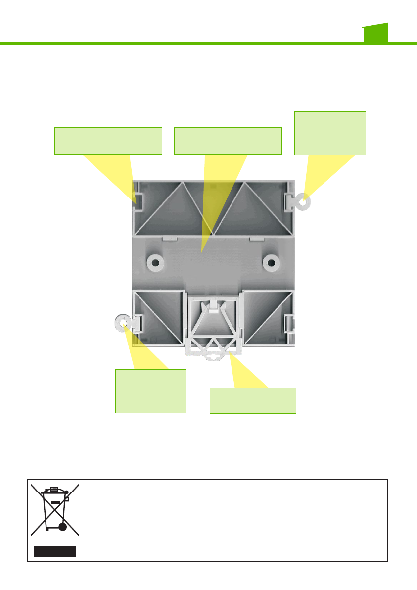
BOARD ASSEMBLY
The board is set to be installed on a 7-module control unit with DIN EN
50022 bar, using the track and lock tabs.
Thanks to the optional side rings, it can be installed on shunt boxes or light
walls with screws.
Do not obstruct the ventilation slats and do not expose the device to
dripping or spraying water.
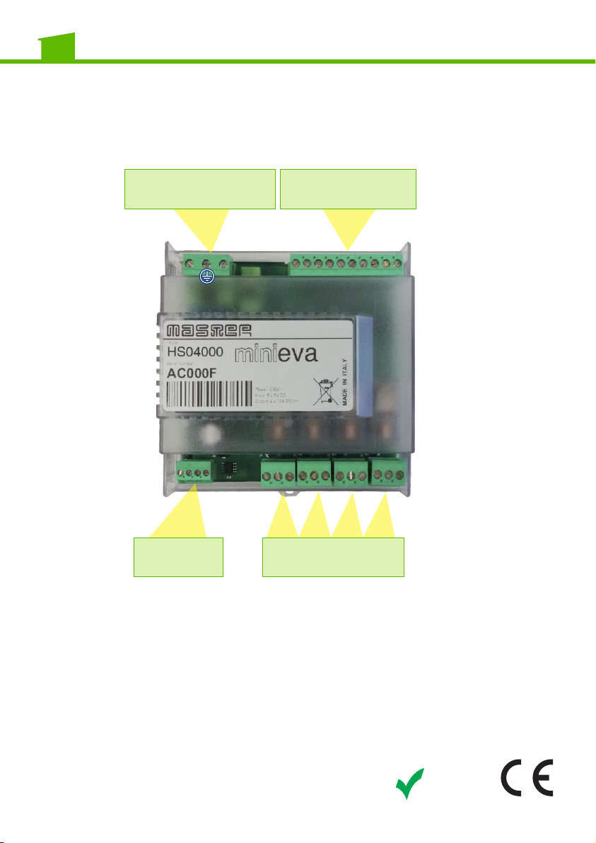
TERMINALS
Terminals are all removable and silk screened to facilitate wiring and
replacement.
ŸPrimary power terminal, is made up of three poles, P (Phase), T
(Ground), N (Neutral) and powers the board at 230Vac.
2x0.5 minimum cable section
ŸRS485bus terminal, made up of 4 poles: +, A, B, -
Poles + and – provide 12-18 Vdc secondary emergency power. This
second power source is optional, powering the board in the event of
230Vac power outage (we recommend you use power sources with
buffer batteries).
Poles A and B provide connections to the Clavis converter or Vesta
board. We recommend a 2x0.5 cable or superior, twisted and low
capacity shielded (<100pF/m).
Optionally, we recommend a 2x0.5 cable or superior, low capacity
twisted (<100pF/m).
Maximum distance from Clavis or Vesta 1 Km
For +, - poles cable 2x.05
ŸDigital input terminal, this is a terminal with 10 poles: C, C, 8, 7, 6, 5, 4,
3, 2, 1.
Internal voltage between the digital inputs and C poles (system) is
5Vdc. Therefore, a clean contact without voltage (switch, shunt, relay,
etc.) must be connected between them (INxx and C). If any external
voltage is applied, this will break the board (see wiring diagram
available from Master).
For each input, use a minimum 1x0.22 cable or higher. Maximum
distance 500 m.For each system “C”, use a minimum 1x0.22 cable or
higher. Maximum distance 500 m.
ŸRelay terminals, there are 4 (one for each relay) and each terminal is
made up of 3 poles, Cx, NO, NCCx corresponds to the system relay,
NO is normally open and NC corresponds to normally closed.
The following can be applied to these terminals:
- 230Vac utilities, lights, appliance sockets, heaters, etc.;
- low voltage utilities, electrical locks, lights, etc.;
- video signals, RBG.
For electrical limits, please see paragraph ELECTRICAL
SPECIFICATIONS
The board can be powered through two terminals, “Primary power” and
secondary emergency power (optional) via the “RS485” bus terminal.
ŸPrimary power: from 200Vac to 250Vac with 50/60 Hz frequency
ŸOptional secondary power: from 12Vdc to 18Vdc
ŸAbsorbed power:
Absorbed power with 4 powered relays: 4W
Absorbed power with 4 idle relays: 2W
ŸAbsorbed power with 4 2W idle relays with SPDT type contacts:
Cos = 1:
12A at 250Vac
12A at 30Vcc
Cos =0,4 L/R = 7 ms:
8A at 250 VAC
8A at 30 VDC
Maximum total load supported by the board: 3000VA (cos = 1)
ŸMaximum switch voltage: 380 Vac, 125 Vdc
ŸMaximum switch current: 16A
ŸMaximum switch power: 4KW
Warning: If terminals are removed, cut-off power upstream (using the
circuit breaker). Removal when live could cause sparks, rusting pins
which could jeopardise good operations over time.
ŸWorking temperature: from -20°C to +85°C
ŸRoom humidity: from 0% to 85%
MiniEva • MiniEvaPower • MiniEvaLight Installation manual • ENGLISH
10 11