Master MVP-150XL Use and care manual

Repair/Parts
MODEL MVP-150XL
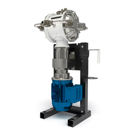
VAPOR RECOVERY PUMP 3A7034A
EN
Designed for hydrocarbon extraction processing.
For LP-Gas Recovery
Electric-Powered
Dual-Diaphragm
Hazardous Location Motor
Stainless Steel Wetted Parts
Rated MAWP: LPG-375-PSI
For professional use only.
Important Safety Instructions
Read all warnings and instructions in this manual
and in the pump Repair/Parts manual before using
the equipment.
Save these instructions.

Contents Contents
Contents
Models...............................................................2
RelatedManuals................................................2
Approvals...........................................................2
Warnings...........................................................3
Troubleshooting..................................................6
Repair................................................................7
PressureReliefProcedure............................7
CheckValveRepair.....................................8
DiaphragmRepair........................................9
CenterSectionRepair..................................11
TorqueInstructions.............................................15
Parts..................................................................17
TechnicalData...................................................21
MVPStandardWarranty.....................................22
Models Models
Models
Includes: Includes:
Includes:
Part Part
PartNumber Number
NumberModel Model
ModelMotor Motor
MotorPump Pump
PumpCO CO
CO2 2
2Cylinder Cylinder
Cylinder
25M869MVP-150XL5HPyesno
Related Related
RelatedManuals Manuals
Manuals
ManualNumberTitle
3A6887ModelMVP-150XLVaporRecoveryPump,Operation
Approvals Approvals
Approvals
Approvals Approvals
Approvals
ClassI–Div.I–GroupCandD,T3C
Motorsonpumpmodel
25M869certiedto:
US
C
ClassI–Div.I–GroupCandD,T3C
ClassII–Div.I–GroupFandG,T3C
23A7034A

Warnings
Warnings Warnings
Warnings
Thefollowingwarningsareforthesetup,use,grounding,maintenance,andrepairofthisequipment.The
exclamationpointsymbolalertsyoutoageneralwarningandthehazardsymbolsrefertoprocedure-specic
risks.Whenthesesymbolsappearinthebodyofthismanualoronwarninglabels,referbacktothese
Warnings.Product-specichazardsymbolsandwarningsnotcoveredinthissectionmayappearthroughout
thebodyofthismanualwhereapplicable.
DANGER
SEVERE SEVERE
SEVEREELECTRIC ELECTRIC
ELECTRICSHOCK SHOCK
SHOCKHAZARD HAZARD
HAZARD
Thisequipmentcanbepoweredbymorethan240V.Contactwiththisvoltagewill
causedeathorseriousinjury.
•Turnoffanddisconnectpoweratmainswitchbeforedisconnectinganycablesand
beforeservicingequipment.
•Thisequipmentmustbegrounded.Connectonlytogroundedpowersource.
•Allelectricalwiringmustbedonebyaqualiedelectricianandcomplywithalllocal
codesandregulations.
WARNING
FIRE FIRE
FIREAND AND
ANDEXPLOSION EXPLOSION
EXPLOSIONHAZARD HAZARD
HAZARD
Flammablefumesinwork work
workarea area
areacanigniteorexplode.Vapororsolventowingthroughthe
equipmentcancausestaticsparking.Tohelppreventreandexplosion:
•Useequipmentonlyinwellventilatedarea.
•Eliminateallignitionsources;suchaspilotlights,cigarettes,portableelectriclamps,and
plasticdropcloths(potentialstaticarc).
•Groundallequipmentintheworkarea.SeeGrounding Grounding
Groundinginstructions.
•Keepworkareafreeofdebris,includingsolvent,ragsandgasoline.
•Donotplugorunplugpowercords,orturnpowerorlightswitchesonoroffwhenammable
fumesarepresent.
•Stop Stop
Stopoperation operation
operationimmediately immediately
immediatelyifstaticsparkingoccursoryoufeelashock. .
.Donotuse
equipmentuntilyouidentifyandcorrecttheproblem.
•Keepaworkingreextinguisherintheworkarea.
3A7034A3

Warnings
WARNING
PRESSURIZED PRESSURIZED
PRESSURIZEDEQUIPMENT EQUIPMENT
EQUIPMENTHAZARD HAZARD
HAZARD
Vapororsolventfromtheequipment,leaks,orrupturedcomponentscansplashintheeyesor
onskinandcauseseriousinjury.
•FollowthePressure Pressure
PressureRelief Relief
ReliefProcedure Procedure
Procedurewhenyoustopoperationandbeforecleaning,
checking,orservicingequipment.
•Tightenallhoseandpressureconnectionsbeforeoperatingtheequipment.
•Checkhoses,tubes,andcouplingsdaily.Replacewornordamagedpartsimmediately.
EQUIPMENT EQUIPMENT
EQUIPMENTMISUSE MISUSE
MISUSEHAZARD HAZARD
HAZARD
Misusecancausedeathorseriousinjury.
•Donotoperatetheunitwhenfatiguedorundertheinuenceofdrugsoralcohol.
•Donotexceedthemaximumworkingpressureortemperatureratingofthelowestrated
systemcomponent.SeeTechnical Technical
TechnicalData Data
Datainallequipmentmanuals.
•Usesolventsthatarecompatiblewithequipmentwettedparts.SeeTechnical Technical
TechnicalData Data
Datainall
equipmentmanuals.Readsolventmanufacturer’swarnings.Forcompleteinformationabout
yourmaterial,requestSafetyDataSheet(SDS)fromdistributororretailer.
•TurnoffallequipmentandfollowthePressure Pressure
PressureRelief Relief
ReliefProcedure Procedure
Procedurewhenequipmentisnotinuse.
•Checkequipmentdaily.Repairorreplacewornordamagedpartsimmediatelywithgenuine
manufacturer’sreplacementpartsonly.
•Donotalterormodifyequipment.Alterationsormodicationsmayvoidagencyapprovals
andcreatesafetyhazards.
•Makesureallequipmentisratedandapprovedfortheenvironmentinwhichyouareusingit.
•Useequipmentonlyforitsintendedpurpose.Callyourdistributorforinformation.
•Routehosesandcablesawayfromtrafcareas,sharpedges,movingparts,andhotsurfaces.
•Donotkinkoroverbendhosesorusehosestopullequipment.
•Keepchildrenandanimalsawayfromworkarea.
•Complywithallapplicablesafetyregulations.
THERMAL THERMAL
THERMALEXPANSION EXPANSION
EXPANSIONHAZARD HAZARD
HAZARD
Liquidssubjectedtoheatinconnedspaces,especiallyinhosesandpipes,cancreatearapid
riseinpressureduetothethermalexpansion.Over-pressurizationcanresultinequipment
ruptureandseriousinjury.
•AllhosesandpipespossiblyexposedtoliquidLP-Gasmustbettedwithproperhydrostatic
reliefvalvestopreventover-pressurization.
•Replacehosesproactivelyatregularintervalsbasedonyouroperatingconditions.
43A7034A

Warnings
WARNING
LP LP
LP- -
-GAS GAS
GASHAZARD HAZARD
HAZARD
LP-Gascancauseseriousinjuryordeathifsplashedintheeyesoronskin,inhaled,orignited.
•ReadSafetyDataSheet(SDS)toknowthespecichazardsofthesolventsyouareusing.
•Storehazardoussolventinapprovedcontainers,anddisposeofitaccordingtoapplicable
guidelines.
BURN BURN
BURNHAZARD HAZARD
HAZARD
Equipmentsurfacescanbecomeveryhotduringoperation.Toavoidsevereburns:
•Donottouchhotequipment.
PERSONAL PERSONAL
PERSONALPROTECTIVE PROTECTIVE
PROTECTIVEEQUIPMENT EQUIPMENT
EQUIPMENT
Wearappropriateprotectiveequipmentwhenintheworkareatohelppreventseriousinjury,
includingeyeinjury,hearingloss,inhalationoffumes,andburns.Thisprotectiveequipment
includesbutisnotlimitedto:
•Protectiveeyewear,andhearingprotection.
•Respirators,protectiveclothing,andglovesasrecommendedbythesolventmanufacturer.
3A7034A5

Troubleshooting
Troubleshooting Troubleshooting
Troubleshooting
•FollowthePressureReliefProcedure,page7,
beforecheckingorservicingtheequipment.
•Checkallpossibleproblemsandcausesbefore
disassembly.
Problem Problem
ProblemCause Cause
CauseSolution Solution
Solution
Pumpheadcentersectionhasno
CO2pressure,orCO2pressureistoo
low.
CheckCO2supply,adjustCO2to150
psi.
Checkvalvesarewornordamaged.Replacethecheckvalves.
Pumpcyclesbutwillnotprimeand/or
pump.
Inletoroutlethoseisshutoff.Removetherestriction.
Thecentersectionisexcessivelyhot.Thedriveshaftisbroken.Replace.
Motororcontrolleriswiredimproperly.Wirepermanual. Motorwillnotrun.
Nopowertomotor.Checkelectricalcircuit.
Themotorisoperating,butthepump
willnotcycle.
Thejawcouplingbetweenthe
motorandgearboxisnotconnected
properly.
Checkthemotorcoupling.
Inletoroutlethoseispinched.Inspecthoses.
Checkvalvesarestickyorbent.Cleanorreplacecheckvalves.
Pumpowrateiserratic.
Diaphragmruptured.Replacediaphragms.
CO2ttingislooseorhosedamaged.InspectCO2ttingsandhoses.
Looseordamagedo-ringsorshaft
sealincentersection.
Rebuildcentersection.
CO2consumptionishigherthan
expected.
Diaphragmruptured.Replacediaphragms.
Pumpleaksexternallyfromjoints.Loosediaphragmcoverscrewsor
ttings.
Checkscrewsandttingsfor
tightness.
63A7034A

Repair
Repair Repair
Repair
Toavoidseriousinjuryordeathfromfumesor
uids,nevermoveorliftapumpunderpressure.If
dropped,thecentersectionmayrupture.Always
followthePressureReliefProcedure,page7,
beforemovingorliftingthepump.
Pressure Pressure
PressureRelief Relief
ReliefProcedure Procedure
Procedure
FollowthePressureReliefProcedure
wheneveryouseethissymbol.
Thisequipmentstayspressurizeduntilpressureis
relievedmanually.Tohelppreventseriousinjury
frompressurizedvapor,followthePressureRelief
Procedurewhenyoustoppumpingforanextended
periodoftime,andbeforeyouclean,check,or
servicetheequipment.
1.Removeelectricpowerfromthesystem.
2.VentallLP-Gasvaporfromthepumpandhoses
accordingtoextractorsysteminstructions.
3.ClosetheshutoffvalveontheCO2cylinder.
4.OnCO2port(E),openthepumpCO2bleedvalve
andCO2supplyvalve.
NOTE: NOTE:
NOTE:Intheeventofadiaphragmrupture,
LP-Gasmaybepresentinthepumpcenter
section.AlwaysventallLP-Gasaccordingto
extractorsysteminstructions.
5.Ifperformingrepairs,removeCO2regulatorand
tankfromthepumppriortoperformingthework.
3A7034A7

Repair
Check Check
CheckValve Valve
ValveRepair Repair
Repair
Manifoldtubingmaybecomehotduringoperation.
Priortoremoval,ensurethattubinghascooled
enoughtohandlesafely.
1.FollowthePressureReliefProcedure,page7.
Removepowerfromthemotor.Disconnectall
hoses.
2.Removemanifoldtubing(14).
3.Removeoutletttingfromthediaphragmcover.
Inspecttheo-ringonthettingfordamage.
Replaceifneeded.
4.Useascrewdrivertoremovetheoutletcheck
valvescrew.
5.Inspectthevalvescrewfordamage.Replaceif
needed.Cleantheoutletvalveareaandinstall
thenewcheckvalve.
6.Torepairtheinletcheckvalve,thediaphragm
covermustberemoved.Usea13mmsocket
wrenchtoremovethe12diaphragmcover
screwsandthediaphragmcover.
7.Useascrewdrivertoremovetheinletcheck
valvescrew.
8.Inspectthevalvescrewfordamage.Replaceif
needed.Cleandtheinletvalveareaandinstall
thenewcheckvalve.
9.Installthediaphragmcoverandlooselyinstall
the12screws(9).
10.Torquethediaphragmcoverscrewsasdescribed
inTorqueInstructions,page15
11.Repeatsteps2-10forothersideofthepump.
12.Restoreallmanifoldtubing.
83A7034A

Repair
Diaphragm Diaphragm
DiaphragmRepair Repair
Repair
Manifoldtubingmaybecomehotduringoperation.
Priortoremoval,ensurethattubinghascooled
enoughtohandlesafely.
Disassemble Disassemble
Disassemblethe the
theDiaphragms Diaphragms
Diaphragms
NOTE: NOTE:
NOTE:Diaphragmkitisavailable.SeePartssection.
1.FollowthePressureReliefProcedure,page7.
Removepowerfromthemotor.Disconnectall
hoses.
2.Removethemanifoldtubing(14).
3.Usea13mmsocketwrenchtoremovethe12
screws(9)fromthediaphragmcovers(8),then
pullthecoversoffofthepump.
4.Toremovethediaphragms,thepistonmustbe
movedfullytothesidetowardthediaphragmto
beremoved.Ifthepumpisnotattachedtothe
motor,turntheshaftbyhandtomovethepiston.
Ifthepumpisstillattachedtothemotor,loosen
thescrewsandremovethemotorfancover.
Turnthefanbyhandinonedirectiontorotatethe
shafttoshiftthepistontooneside.
5.Holda28mmwrenchonthewrenchatsofthe
exposedpistonshaft.Useanotherwrench(10
mmhexkey)ontheshaftbolttoremoveit.Then
removeallpartsofthediaphragmassembly.
6.Rotatethedriveshafttomovethepistonfullyto
theoppositeside,asdescribedinstep4.Then
removetheotherdiaphragm.assembly.
7.Tocontinuewithdisassembly,see
DisassembletheCenterSection,page11.
3A7034A9

Repair
Reassemble Reassemble
Reassemblethe the
theDiaphragms Diaphragms
Diaphragms
TIP: TIP:
TIP:Ifyouarealsorepairingorservicingthe
centersection(driveshaft,piston,etc.),see
CenterSectionRepair,page11,beforeyouputthe
diaphragmsbackon.
1.Cleanallpartsandinspectforwearordamage.
Replacepartsasneeded.Besurethecenter
sectioniscleananddry.
2.Thoroughlycleanorreplacethepistonshaftbolt
(7).Installtheo-ring(6).
3.Assemblethevaporsideplate(5),the
diaphragms(3,4),andtheCO2sidediaphragm
plate(2)ontheboltexactlyasshown.
4.Cleanthefemalethreadsofthepistonshaft
withawirebrushdippedinsolventtoremove
anyresidualthreadlocker.Applythread-locking
primerandallowittodry.
5.Applymedium-strength(blue)threadlockerto
thethreadsofthebolt.
6.Rotatethedriveshafttomovethepistonfully
tooneside.Seeinstructionsinstep4of
DisassembletheDiaphragms,page9.
7.Onthesidewheretheshaftextendsoutwardthe
farthestfromthecentersection,holda28mm
wrenchonthewrenchatsofthepistonshaft.
Screwtheboltontotheshaftandtorqueto100
ft-lb(135N•m).
8.Repeattoinstalltheotherdiaphragmassembly.
9.Attachthediaphragmcoversandvaporcaps.
Applymedium-strength(blue)threadlockertothe
screwthreads.SeeTorqueInstructions,page15,
totighten.
NOTICE NOTICE
NOTICE
•Afterreassembly,allowthethreadlocker
tocurefor12hours,oraccordingto
manufacturer’sinstructions,priorto
operatingthepump.Damagetothepump
willoccurifthediaphragmshaftboltloosens.
•Applyanti-seizetothreadsonstainlesssteel
ttingsusedonthemanifoldtubes.
10.Attachallmanifoldtubing.
103A7034A

Repair
Center Center
CenterSection Section
SectionRepair Repair
Repair
Disassemble Disassemble
Disassemblethe the
theCenter Center
CenterSection Section
Section
Seetheillustrationsonpage18.
1.FollowthePressureReliefProcedure,page7.
Removepowerfromthemotor.Disconnectall
hoses.
2.Removethemanifolds.
3.Removethecoversanddiaphragmsasdirected
inDisassembletheDiaphragms,page9.
TIP: TIP:
TIP:Removepumpfromstandandsecure
gearboxtobench.Leavethepumpconnected
tothemotor.
4.Removethedriveshaft:
a.Usea10mm(M8)hexwrenchtoremove
4bolts(117).Pullthepumpoffofthe
alignmenthousing(116).
TIP: TIP:
TIP:Itmaybenecessarytotapthepumpwith
arubbermallettodisengagethecoupler.
b.RemoveCO2inletttings.Usea30mm
socketwrenchtoremovethebearingbolt
(106)andtheo-ring(108).
c.Turntheshaftsothegrooveontheshaftis
inlinewiththealignmentmarkingsonthe
centersection.
d.Usea3/4–16bolttopushoutthedrive
shaftassembly(112).Youcanalsousethe
bearingbolt(106),butremovethebearing
(107)rst.Besurethatthegrooveonthe
driveshaftremainsalignedwiththemarkings
inthecentersection.
NOTICE NOTICE
NOTICE
Properalignmentisessential.Donot
applymorethanabout10in-lb(1.1N•m)
oftorque.Excessivetorquecouldstrip
thehousingthread.Ifyouencounter
resistance,checkalignmentorcontact
yourdistributor.
e.Theshaftcoupler(113)mightcomeoutwith
thedriveshaftassembly.Ifnot,reachinto
thealignmenthousing(116)andremovethe
shaftcoupler(113).
f.Removethesealcartridge,o-ring(109)and
theradialseal(111)witho-ring(111a)from
thedriveshaftassembly.
5.Slidethepistonassembly(102)outofthecenter.
3A7034A11

Repair
Reassemble Reassemble
Reassemblethe the
theCenter Center
CenterSection Section
Section
1.Cleananddrythecenterhousing(101),the
centerofthepiston(105)andthedriveshaft
(109).
2.Inspectthepistonforexcessivewearandreplace
ifneeded.Greasethepistonasshownandinstall
itinthecentersectionwiththegrooveinlinewith
thealignmentmarkingsonthecentersection.
3.Installtheo-ring(113)andthebearingbolt(114).
Applymedium-strength(blue)threadlockerand
torquetheboltto15–25ft-lb(20–34N•m).Be
surethatthebearing(112)isinthegrooveon
thepiston,asshown.Besurethatthepiston
movesfreely.
4.Installthedriveshaft:
a.Besurethesealingsurfaceofthedriveshaft
(109)isclean.Installthesealcartridgeand
radialseal(107)onthedriveshaft.Thelips
ontheradialseal(107)mustfaceIN IN
INtoward
thecenter.
b.Installo-ring(108)tothecenterhousing
(101).
c.Applyanti-seizelubricantonthemating
edgesofthedriveshaft,asshowninthe
illustration,page18.
d.Centerthepistoninthehousingandinstall
thedriveshaftassembly(109)intothecenter
housing(101)withthegroovefacingup.
e.Inspecttheshaftcoupler(115)forwearand
replaceifneeded.Installonthedriveshaft.
5.Besurethegearboxcoupler(11x)isaligned
properly.Turnbyhandifneeded.Connectthe
pumptothegearboxassembly,engagingthe
couplers.
6.Applymedium-strength(blue)threadlockerand
installthehousingscrews(111).Tightenabout
5turnsatatime,inacrisscrosspattern,tofully
engagethecoupler.Torqueto130–160in-lb
(15–18N•m).
7.InstallCO2inletttings.
8.SeeReassembletheDiaphragms,page10,and
CheckValveRepair,page8.
123A7034A

Repair
1
Applymedium-strength(blue)thread
lockertothreads.
2
Torqueto15–25ft-lb(20–34N•m).
3
LipsmustfaceIN IN
INtowardthecenter.
4
Applyanti-seizelubricantliberallyon
theradialsurfacesofthedriveshaft
assembly.
5
Installthedriveshaftassemblywith
thegroovefacingup.
6
Tightenscrewsinacrisscross
pattern,5turnsatatime,toengage
thecouplerevenly.Torqueto
130–160in-lb(15–18N•m).
7
Applylubricanttoinnermating
surface.
3A7034A13

Repair
Disconnect Disconnect
Disconnectthe the
theMotor Motor
Motorand and
andGearbox Gearbox
Gearbox
NOTE: NOTE:
NOTE:Normally,themotorremainsconnectedtothe
gearbox.Disconnectthemotoronlyifyoususpect
thatthemotororgearboxmustbereplaced.
1.Removethepumpfromthestand.
2.Usea3/4in.socketwrenchtoremove4screws
(130b).
3.Pullthemotor(130d)straightoffofthegearbox
(130a).
4.Usea3/4in.socketwrenchtoremove4screws
(116).Pullthegearboxoffofthealignment
housing.
143A7034A

TorqueInstructions
Torque Torque
TorqueInstructions Instructions
Instructions
Ifdiaphragmcoverorvaporcapfastenershavebeen
loosened,itisimportanttotorquethemusingthe
followingproceduretoimprovesealing.
NOTE: NOTE:
NOTE:Coverandcapscrewshaveathread-locking
adhesivepatchappliedtothethreads.Ifthispatch
isexcessivelyworn,thescrewsmayloosenduring
operation.Replacescrewswithnewonesorapply
medium-strength(blue)threadlockertothethreads.
NOTE: NOTE:
NOTE:Alwayscompletelytorquecoversandcaps
beforetighteningmanifolds.
1.Startallscrewsafewturns.Then,turndown
eachscrewjustuntilheadcontactscover.
2.Turneachscrewby1/2turnorlessworkingina
crisscrosspatternintheordershowntospecied
torque.
Diaphragm Diaphragm
Diaphragmcovers covers
coversand and
andvapor vapor
vaporcap cap
capscrews: screws:
screws:90
in-lb(10.2N•m)
3A7034A15

Parts
Parts/Kits Parts/Kits
Parts/KitsQuick Quick
QuickReference Reference
Reference
Usethistableasaquickreferenceforkits.Gotothekittableonpage20forafulldescriptionofkitcontents.
Ref. Ref.
Ref.Kit Kit
KitRef Ref
RefDescription Description
DescriptionQty. Qty.
Qty.
1———MODULE,drive;
Seepage
19.
1
2———PLATE,CO2side2
3207
208
DIAPHRAGM2
4207DIAPHRAGM,backer2
5———PLATE,vaporside2
6207
208
O-RING,fordiaphragm
shaftbolt
2
7207
208
BOLT,shaft2
8217DIAPHRAGMCOVER,SST2
9217SCREWS,cover,M8x1.25
x25mm
24
10216
217
CHECKVALVE,reed4
11216
217
SCREW4
12216
217
O-RING4
13215FITTING,adapter4
14215TUBE,manifold4
15215FITTING,JICx3/42
16215FITTING,adapter2
17215
221
PLUG3
23220BRACKET1
24219FRAME,leg2
25219BRACE,frame1
26223BRACKET,cylinder1
27223PAD,cylinder(notshown)1
28214BOLT,1/2x1.54
Ref. Ref.
Ref.Kit Kit
KitRef Ref
RefDescription Description
DescriptionQty. Qty.
Qty.
29219
220
SCREW9
30219
220
WASHER,lock13
31219NUT13
32———CLAMP,ball,cordlock2
33———CORD1
34219
220
PLUG6
35221FITTING,adapter1
36221CROSS,pipe1
37221VALVE,ball2
38218
221
FITTING,elbow,1/4teex
1/4npt
3
44———SCREW,ground,M5x0.81
52219PLUG4
56218REGULATOR,CO21
58�LABEL,notice1
60BRACE1
61WASHER,at,5/161
62WASHER,lock1
63SCREW,cap,3/8–161
64WASHER2
65�LABEL,safety1
68HOSE,airAR
———
Notsoldseparately.
�Replacementsafetylabels,signs,tags,andcards
areavailableatnocost.
183A7034A

Parts
Ref Ref
RefKit Kit
KitRef Ref
RefDescription Description
DescriptionQty Qty
Qty
101209HOUSING,center,
assembly;
includesplugs
1
102O-RING,374,Buna-N2
103RING,chamber2
104SCREW,hexwasherhead16
105———PISTON,assembly1
106CARTRIDGE,seal1
107204
205
SEAL,radial1
107a204
205
O-RING,seal1
108204
205
O-RING1
109204SHAFT,drive1
110210HOUSING,alignment1
111———SCREW4
112———BEARING,camfollower1
113———O-RING,Size019,
Fluoroelastomer
1
114———BOLT,bearing1
115203COUPLER,shaft1
116PIN,pump1
117209PLUG,pipe,headless2
119———COUPLER,gearbox1
120———MAGNET1
121214SCREW,cap,hexhead,
M8x20mm
4
130a214GEARBOX1
130c———COUPLER
130d212MOTOR1
116–——SCREW,sockethead,
M10x30mm
1
117210SCREW,sockethead,M6
x40mm
4
———
Notsoldseparately.
Kit Kit
KitTable Table
Table
Ref. Ref.
Ref.Kit Kit
KitDescription Description
DescriptionQty. Qty.
Qty.
20325R035Kit,coupler,includes:Ref1151
20425R036Kit,shaftassembly,includes:
Ref107,107a,108,1091ea
20525R066Kit,redialseal,includes:
106,107,107a,1081ea
20625r037Kit,piston,includesRef1051
20725r038Kit,diaphragm,2–piecePTFE,
includes:
Ref3,4
1ea
20925r039Kit,centersection,includes:
Ref1011
21025r040Kit,alignmenthousing,includes:
Ref110
Ref1111
4ea
21225r041Kit,motor,5HP,ameproof,
includes:
Ref130d1
21425r042Kit,gearreducer,includes:
Ref130a
Ref130b1ea
4ea
21525R043Kit,manifoldassembly,includes:
Ref14
Ref15,172ea
1ea
21625R044Kit,checkvalves,includes
Ref10,114ea
21725R045Kit,diaphragmcover,includes:
Ref8
Ref9
Ref12,13
1ea
12ea
2ea
21825D049Kit,CO2regulator,includes:
Ref38,561ea
21925D050Kit,standlegs,includes:
Ref25
Ref24
Ref52
Ref29
Ref30,31
Ref34
1ea
2ea
4ea
9ea
13ea
6ea
22025R046Kit,standbracket,includes:
Ref23
Ref29-311ea
4ea
22125D052Kit,ll/ventttings,includes:
Ref17,35,36
Ref37,381ea
2ea
22225R047Kit,tting,includesRef162
22325R067Kit,CO2holder,includes:
Ref26,271ea
203A7034A
Other manuals for MVP-150XL
1
Table of contents
Other Master Water Pump manuals
Popular Water Pump manuals by other brands

Reefe
Reefe RainPro RM5000 Installation Guide & Owners Information

Pentair
Pentair HYDROMATIC H3H Installation and service manual

Champion
Champion 66525 owner's manual

webtrol
webtrol EZ Series Maintenance & Repair Manual

Westfalia
Westfalia 84 80 51 instruction manual

Oase
Oase Aquarius Universal 21000 operating instructions

Edwards
Edwards E-LAB 2 instruction manual

ITT
ITT ST31 Installation, operation and maintenance instructions

EINHELL
EINHELL ROYAL TMP 257-S operating instructions

Einhell Royal
Einhell Royal HWA 1100 NIRO operating instructions

Antech
Antech LARA DS user manual

Buffalo Tools
Buffalo Tools TWPUMP Assembly & operating instructions