The Mate Logo is a registered trademark of Mate Precision Tooling Inc.
Mate Precision Tooling • 1295 Lund Boulevard • Anoka, Minnesota 55303 USA • Phone 763.421.0230 • 800.328.4492 • Fax 763.421.0285 • 800.541.0285
Dimensions in Inches(millimeters) mate.com
Mate Pilot™ Turret Calibration System
Installation and Operation Instructions
Alignment Mode for Machines with Movable Upper and Lower Holders
Alignment Mode—For thick turret punch press with removable upper and lower holders.
Used to restore the concentric and angular alignment of each station with the same or better precision as the
initial machine installation. Achieving precise alignment improves piece part quality, extends tool life, and
increases productivity.
Install the Instruments into the Punch Press
1. Rotate the turret until the station to be aligned is in the tool change position, then remove punch holder and/or die as applicable.
(Tip: Tooling in adjacent stations should also be removed to provide more work space.)
2. Inspect the upper tool holder for damage. Pay particular attention to the tool holder alignment keys. The upper calibration instrument
should slide freely in the upper tool holder. Repair as required, prior to alignment.
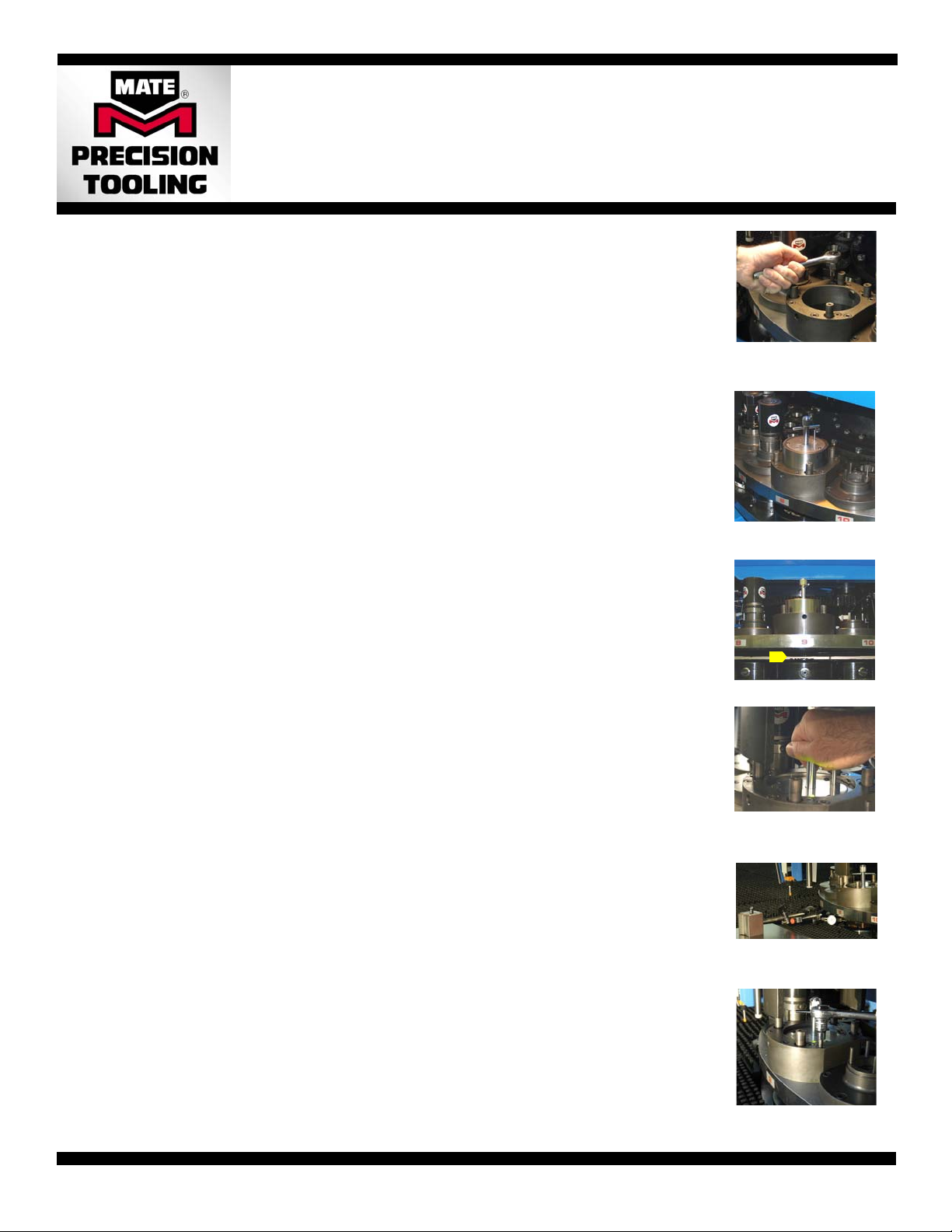
3. Loosen the screw(s) that hold the upper and lower tool holders in place. See photo 1. (Tip: Any thread retaining compound used in
previous installations should be removed.)
4. Tighten the screw(s) mentioned above until just snug. The upper and lower tool holders will need to slide during the alignment
process.
5. Install the lower calibration instrument into the die holder and tighten the clamp screw(s) as you would for a die.
6. Install the upper calibration instrument into upper holder, gently lowering the instrument until the lock pawl (see Figure 1 on page 1)
rests on the top of the turret key in the turret bore. Caution: Do not allow the upper instrument to drop onto the turret key or through
the turret bore as this may damage the instrument and/or the machine. See photo 2.
7. Look into the turret gap to ensure the threaded end of the length adjustment handle is not engaged with the lower calibration
instrument. See photo 3.
Align Upper and Lower Holder
1. Rotate the turret until the station to be aligned is under the ram. Note: The turret must be locked in place. For auto-index stations,
the auto-index pins must be engaged.
2. Lower the upper instrument gently by depressing the release button and lowering the instrument using the adjustment handle, until
the threaded end of the adjustment handle rests on the top of the lower instrument. Caution: Do not allow the upper instrument to
drop through the turret bore as this may damage the instrument and/or the turret bore.
3. Reach into the machine and tighten the adjustment handle using the T-bar, until the interlocking teeth of the upper and lower
instruments are fully engaged. The indicator light will change color from red, to yellow, and then to green (see photo 4). During this
process the upper and lower tool holders will be adjusted into precise concentric and angular alignment. Caution: Do not use any
device, other than the T-bar, to tighten the adjustment handle. Excessive torque may damage the machine and/or the calibration
instruments.
Align the Station to the Punch Press:
1. Attach the alignment bar to the upper calibration instrument using the M4 screw provided.
2. Clamp an approximately 24”(600mm) x 48”(1200mm) piece of mild steel 0.100(2.50) thick or thicker into the punch press work
holder clamps. See photo 5.
3. Mount a dial-test-indicator (DTI) with a magnetic base in a suitable position so the probe can be moved along the length of the
alignment bar. See photo 5.
4. Use the manual jog mode on the machine control to move the sheet metal with the DTI attached, so that the probe of the DTI can
move along the full length of the alignment bar. The total indicator reading (TIR) should be <0.001(0.02) when the tool holder is
correctly aligned. See photo 5.
5. Use the adjustment bar to rotate the calibration instruments (and the upper and lower tool holders) until the total indicator reading
(TIR) of <0.001(0.02) is achieved. You may need to move the sheet with the DTI back and forth several times until the desired
reading is achieved. TIP: If it is difficult to rotate the calibration instruments, slightly loosen one or more of the retaining screws.
6. Tighten all the accessible retaining screws. See photo 6.
7. Recheck the alignment (repeat steps 4 to 6) to confirm the tool holders did not move during tightening. If the TIR of <0.001(0.02) is
achieved, then proceed to the next step. If not, repeat steps 4 to 6.
8. Remove the alignment bar.
9. Lift the upper instrument gently, using the length adjustment handle, until the lock pawl rests on the top surface of the turret key.
10. Look into turret gap to ensure the threaded end of the length adjustment handle is not engaged with the lower calibration
instrument.
11. Rotate the turret until the station that has been aligned is returned to the tool change position. Caution: Do not rotate the turret with
the two halves of the calibration instrument tightened together.
12. Tighten any retaining screws not previously tightened in step 6 above.
13. Proceed to step 5 of the Verification Mode Procedure.
Photo 1: Loosen upper and
lower tool holder retaining
screws
Photo 3: Check disengagement
Photo 4: Align the station,
using the T-bar to tighten the
adjustment handle until the
light goes green.
Photo 5: Draw the probe of the
dial-test-indicator along the
length of the alignment bar.
Photo 2: Install upper and
lower instruments
Photo 6: Tighten the upper and
lower tool holder retaining
screws.